
TEMPLATES

Start with your hardware.

Explore a real test procedure, understand the setup, then make it your own.

Find your test

47 templates

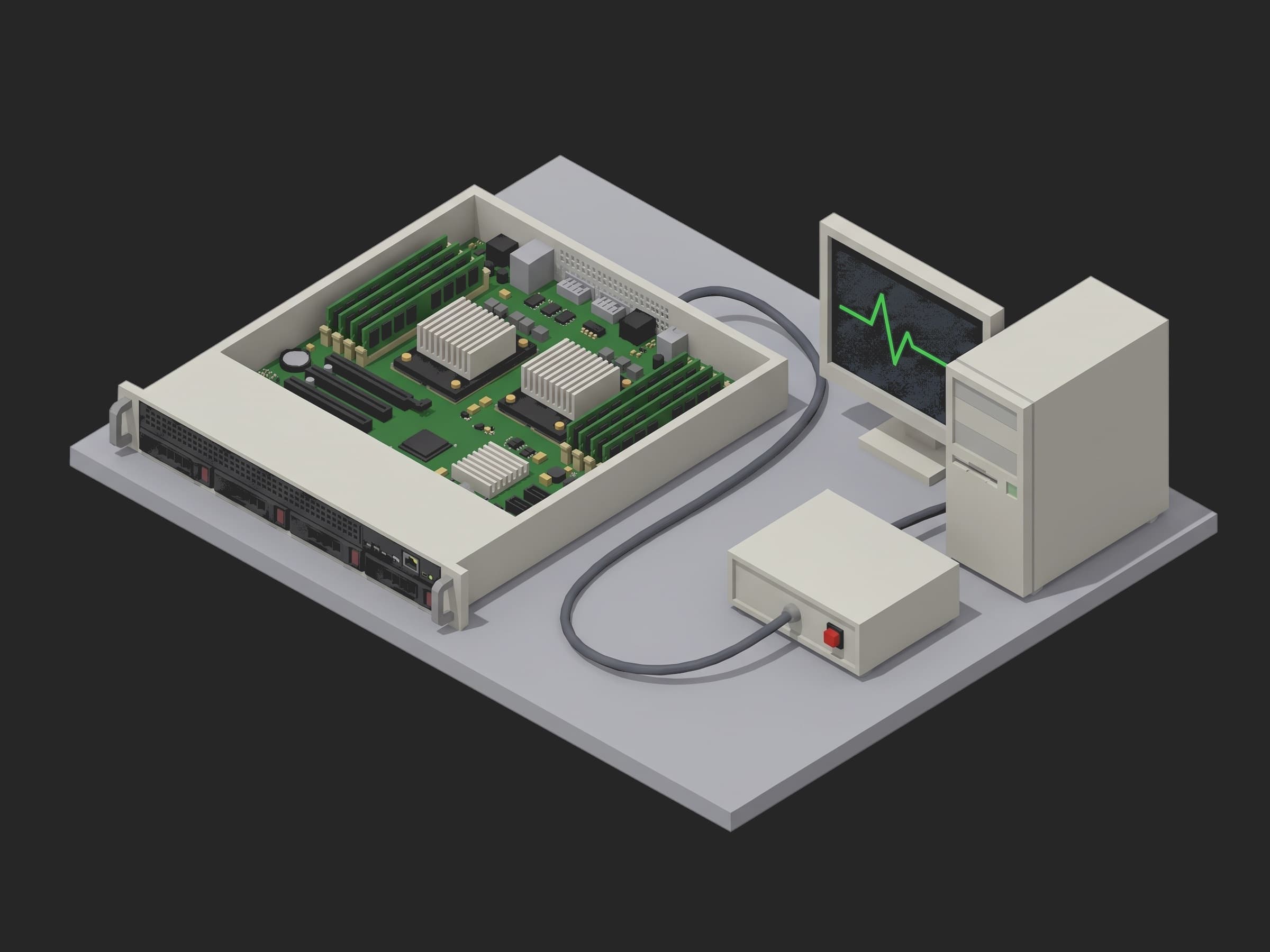
Server L10 System Test and Run-In test setup

Server L10 System Test and Run-In

L10 test of a 2U dual-socket server: Redfish inventory against the golden config, memtest, PCIe links, fio, NIC loopback, TDP stress and a 24 h run-in.
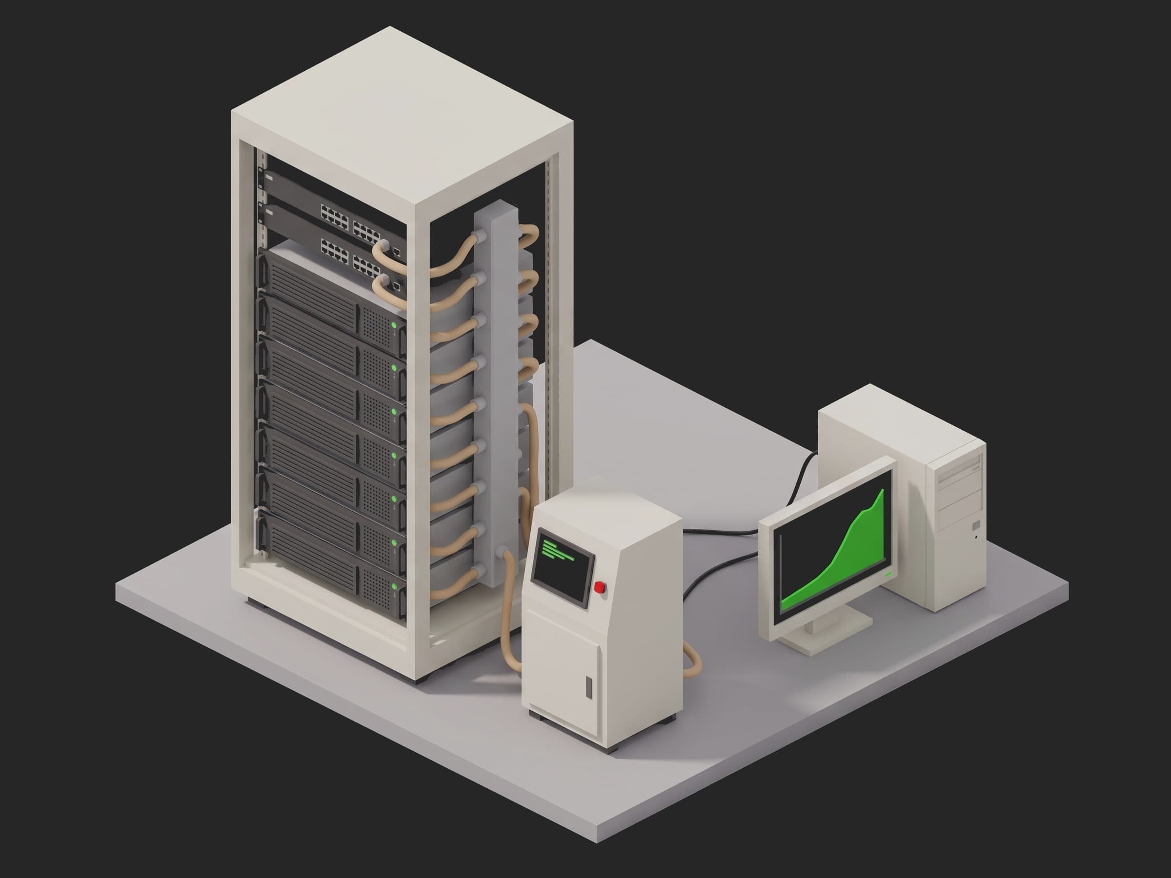
Rack L11 Integration Test test setup

Rack L11 Integration Test

Integrate a liquid-cooled AI rack at L11: build record, cable map vs LLDP, gaseous leak test, PG25 fill and flow, ports at rate, NCCL all-reduce, 24 h soak.
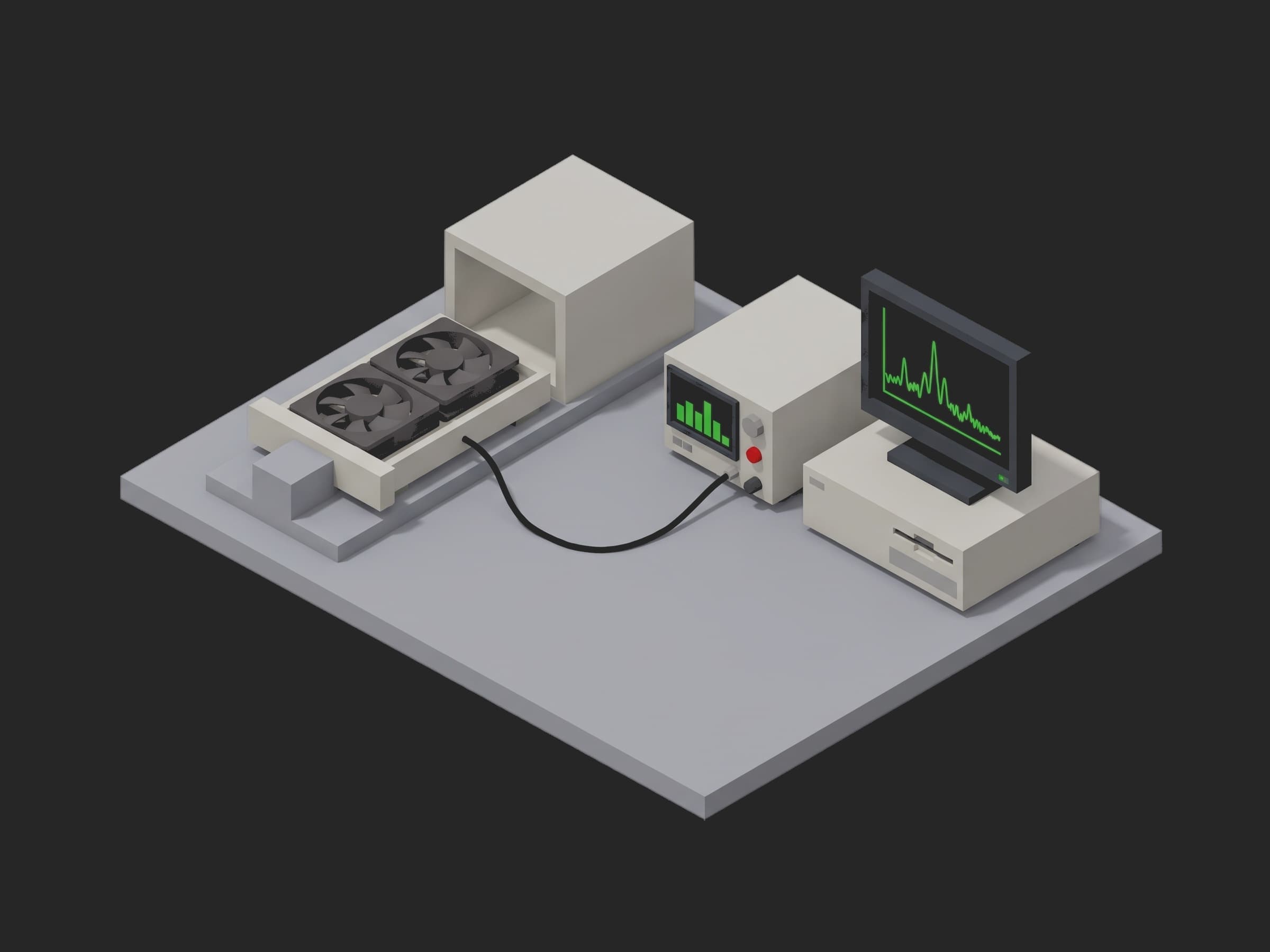
Server Fan Tray End-of-Line Test test setup

Server Fan Tray End-of-Line Test

End-of-line test of a dual-rotor 12 V server fan tray: PWM to RPM curve, 13.2 V start-up current, tach integrity, airflow, vibration spectrum and dBA.
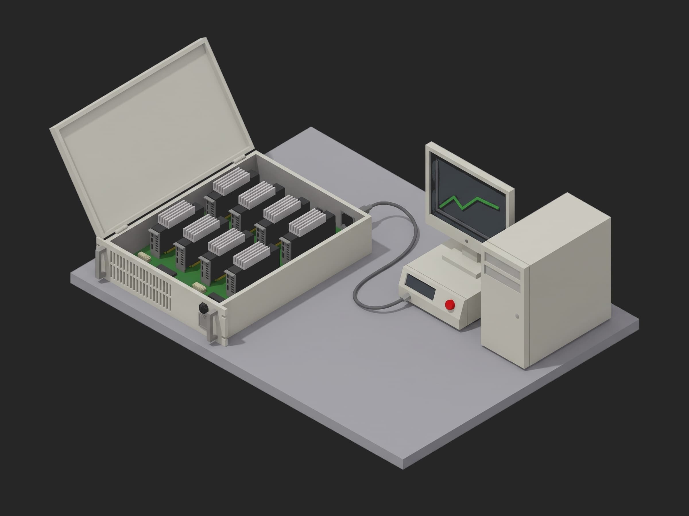
GPU Baseboard Diagnostic Ladder test setup

GPU Baseboard Diagnostic Ladder

L10 diagnostic ladder for an 8-GPU HGX baseboard: DCGM levels 1 to 4 as executable phases, targeted power to TDP, NCCL all-reduce, HBM memtest, 24 h soak.
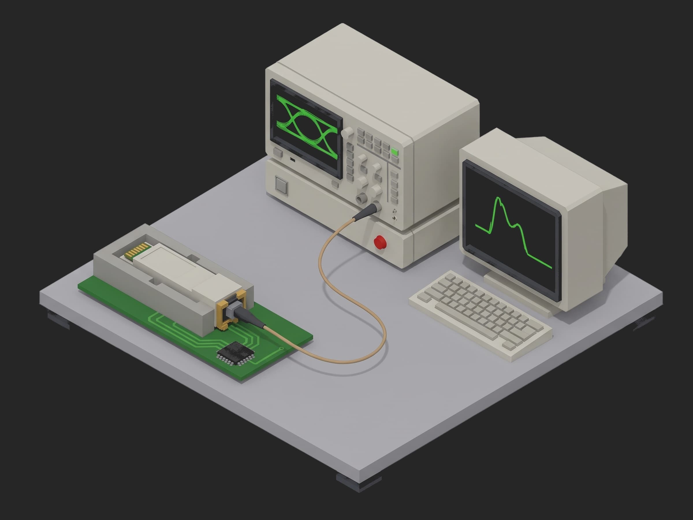
400G DR4 Transceiver TP2 Test test setup

400G DR4 Transceiver TP2 Test

End-of-line test of a 400GBASE-DR4 QSFP-DD transceiver: TP2 launch power, OMA, ER and TDECQ per lane, Rx sensitivity to BER 2.4e-4, SRS and temperature corners.
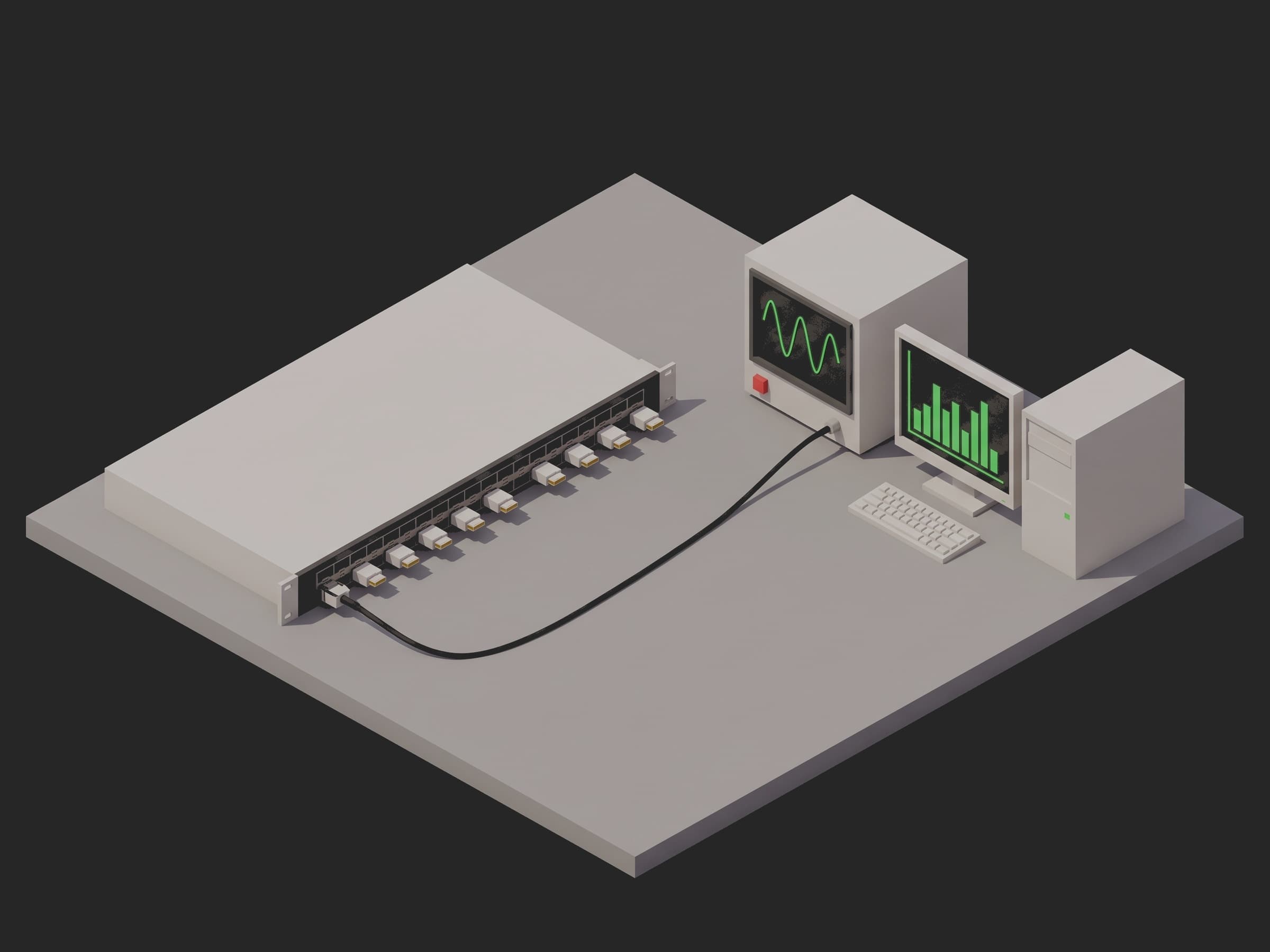
Switch Port PRBS BER and Snake Test test setup

Switch Port PRBS BER and Snake Test

Accept a 32-port 400G switch: PRBS31 BER on all 256 lanes against the 802.3 budget, worst eye per port, a line-rate snake through every port, FEC and CMIS.
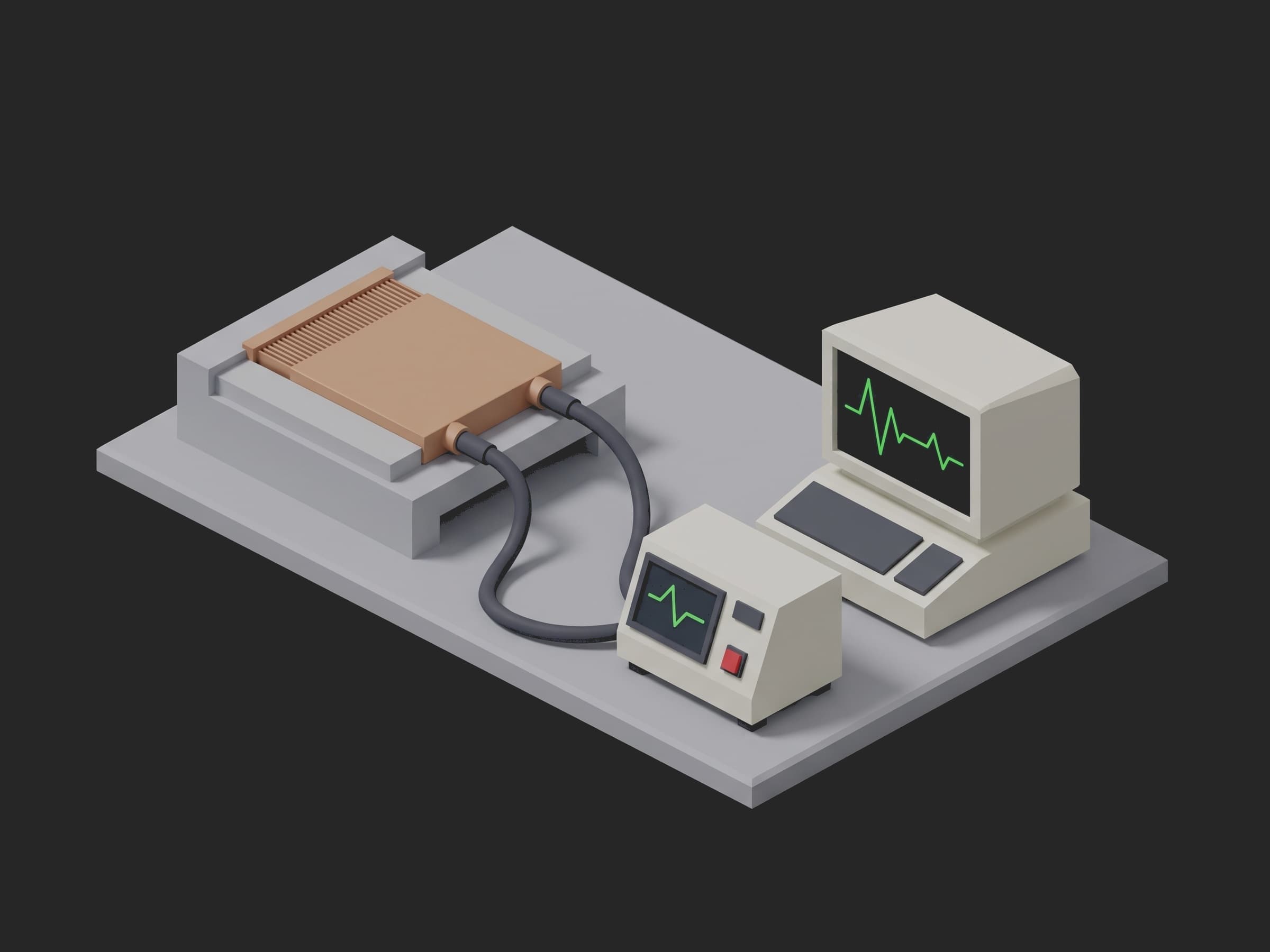
Cold Plate Leak and Thermal Qualification test setup

Cold Plate Leak and Thermal Qualification

Qualify a direct-to-chip cold plate: N2 pressure decay, hydrostatic at 1x and 3x MOP, pressure drop as loop minus bypass, thermal resistance and a flush.
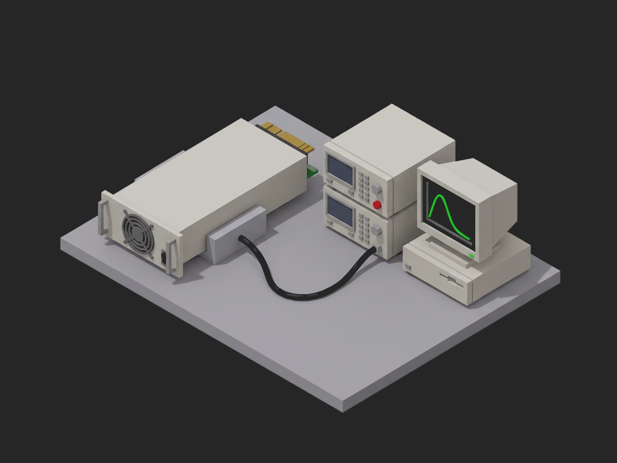
ORV3 PSU Acceptance Test test setup

ORV3 PSU Acceptance Test

Acceptance of an OCP ORV3 12 kW PSU module: hipot, inrush, efficiency vs Titanium, ripple, load step, hold-up at 100 and 120 %, OVP OCP OTP trips, blackbox.
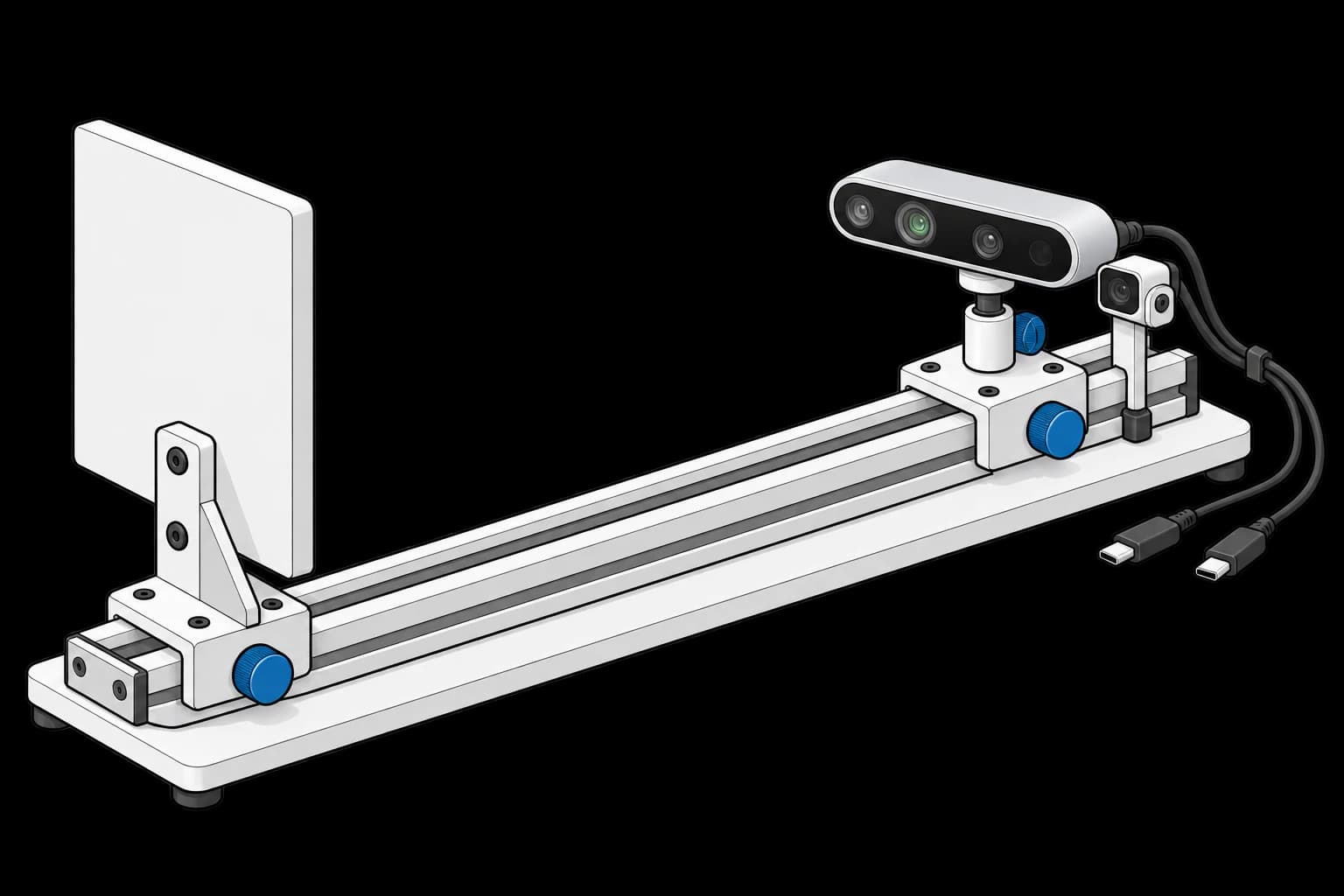
RealSense D435 camera and reference sensor facing a flat target on an adjustable rail

RealSense Depth Camera Acceptance Test

Check depth accuracy and noise before integrating a camera.
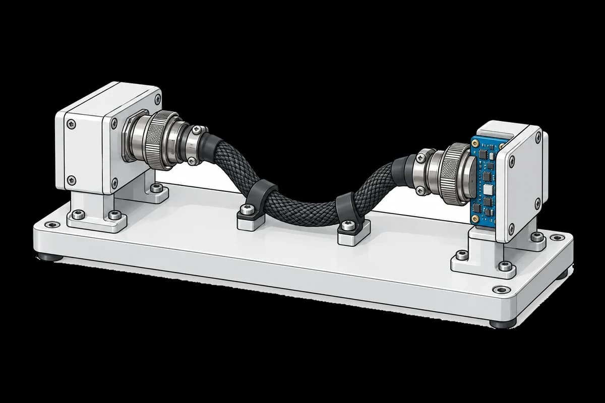
Wire harness connected to continuity and electrical safety test fixtures

Harness Continuity and Hipot Test

Check continuity, insulation and shield bonding on every harness.
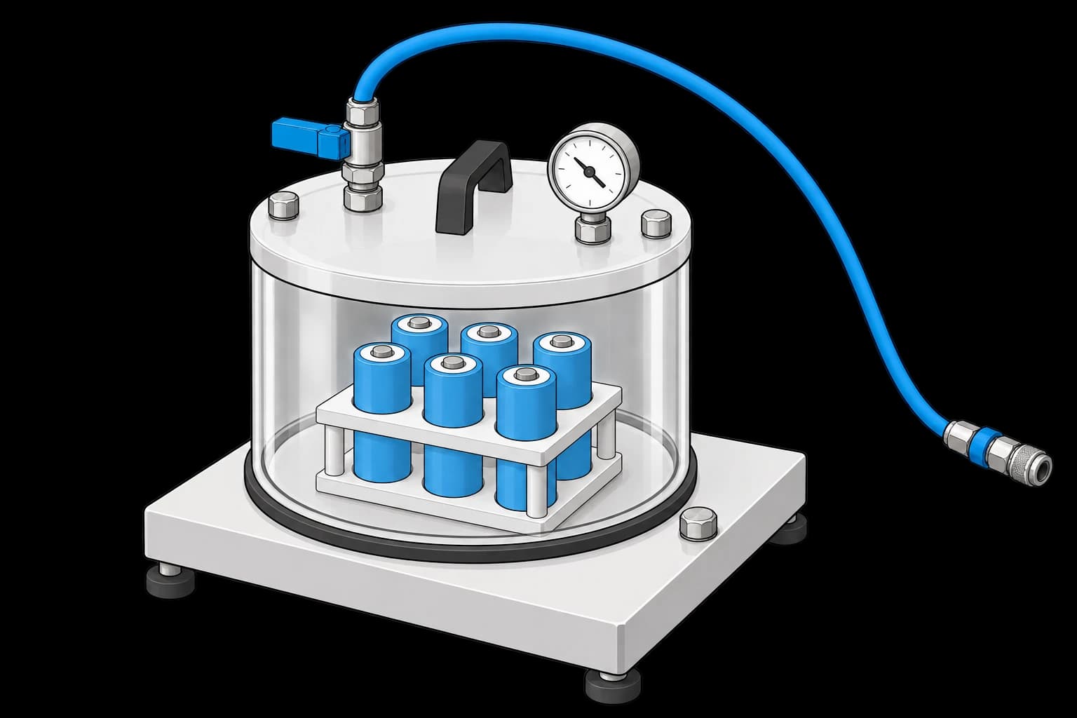
Cylindrical battery cells supported in a vacuum chamber with an external vacuum connection

Battery Cell Screening with Vacuum

Compare cell performance before and after vacuum exposure.
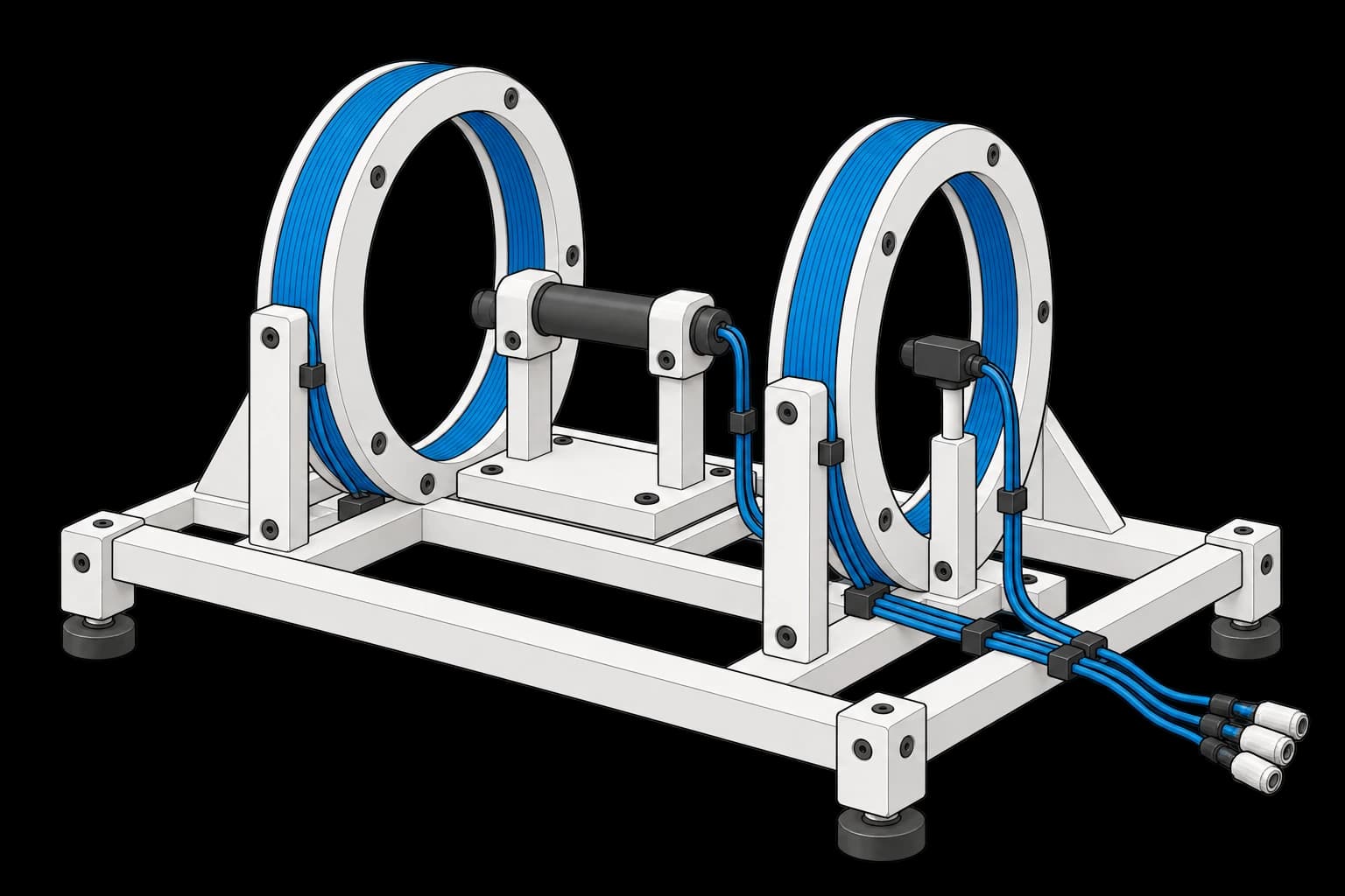
Magnetorquer rod and magnetic probe between a pair of coaxial field coils

Magnetorquer Dipole Moment Test

Verify a torque rod’s magnetic response, polarity and insulation.
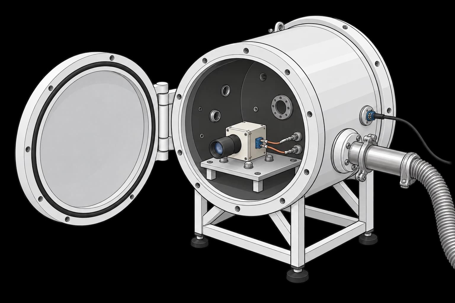
Star tracker on a platen inside an open thermal-vacuum chamber with separate feedthroughs

TVAC Bakeout and Thermal Cycling

Check a star tracker through vacuum bakeout and temperature cycles.
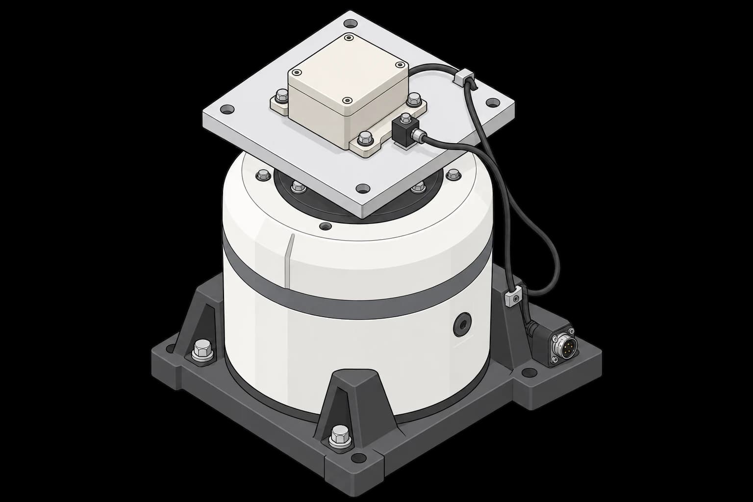
Electronic unit and accelerometer bolted to a shaker fixture plate

Random Vibration Acceptance Test

Verify a subsystem survives vibration along all three axes.
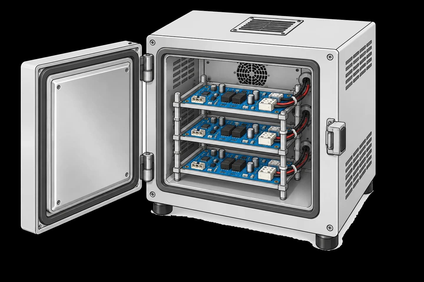
Open thermal chamber holding blue power distribution boards

PCDU Thermal Cycle and Burn-In

Check power distribution through thermal cycles and extended operation.
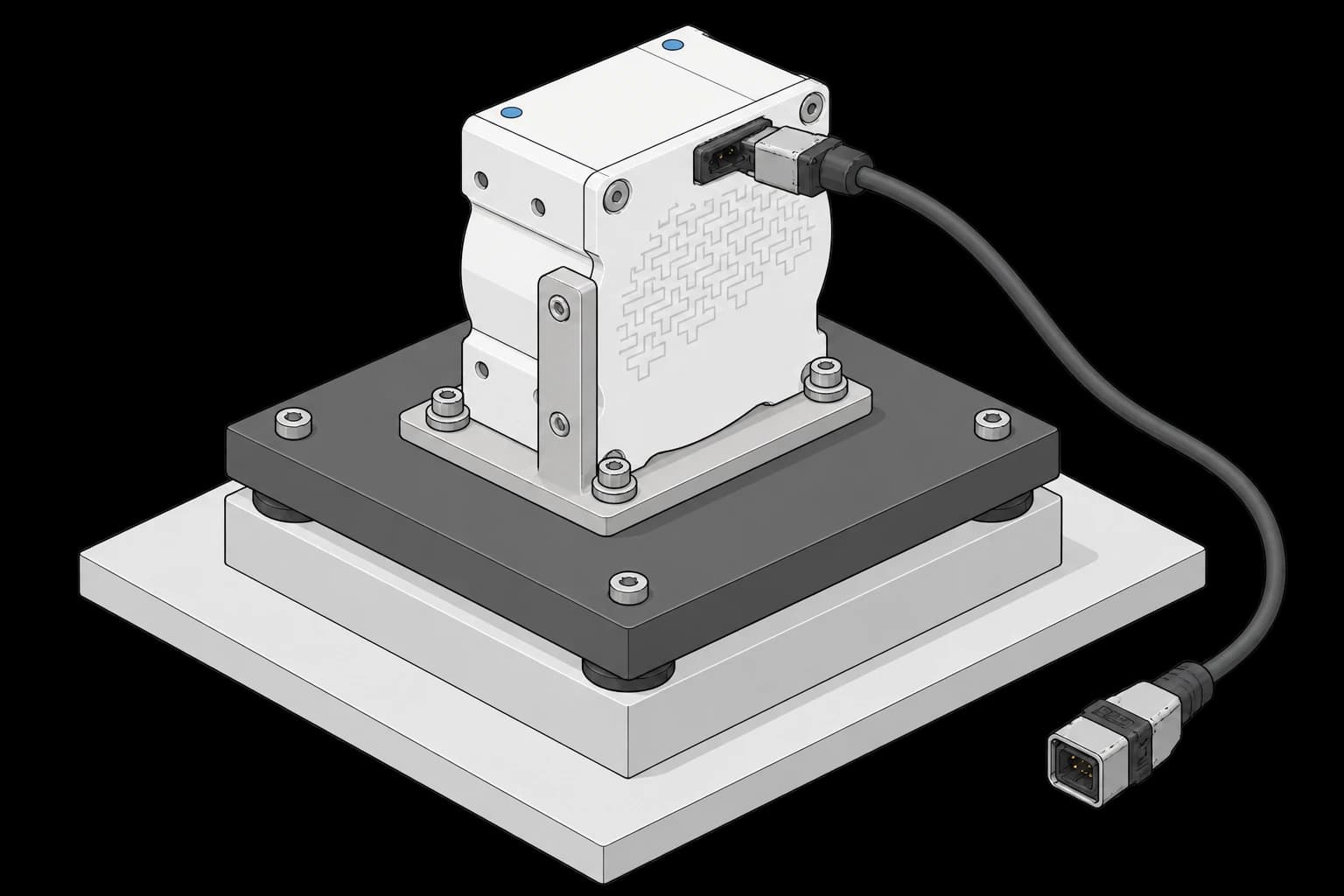
Enclosed reaction wheel bolted to an adapter on a test platform

Reaction Wheel Acceptance Test

Measure wheel balance, friction and exported forces across speed.
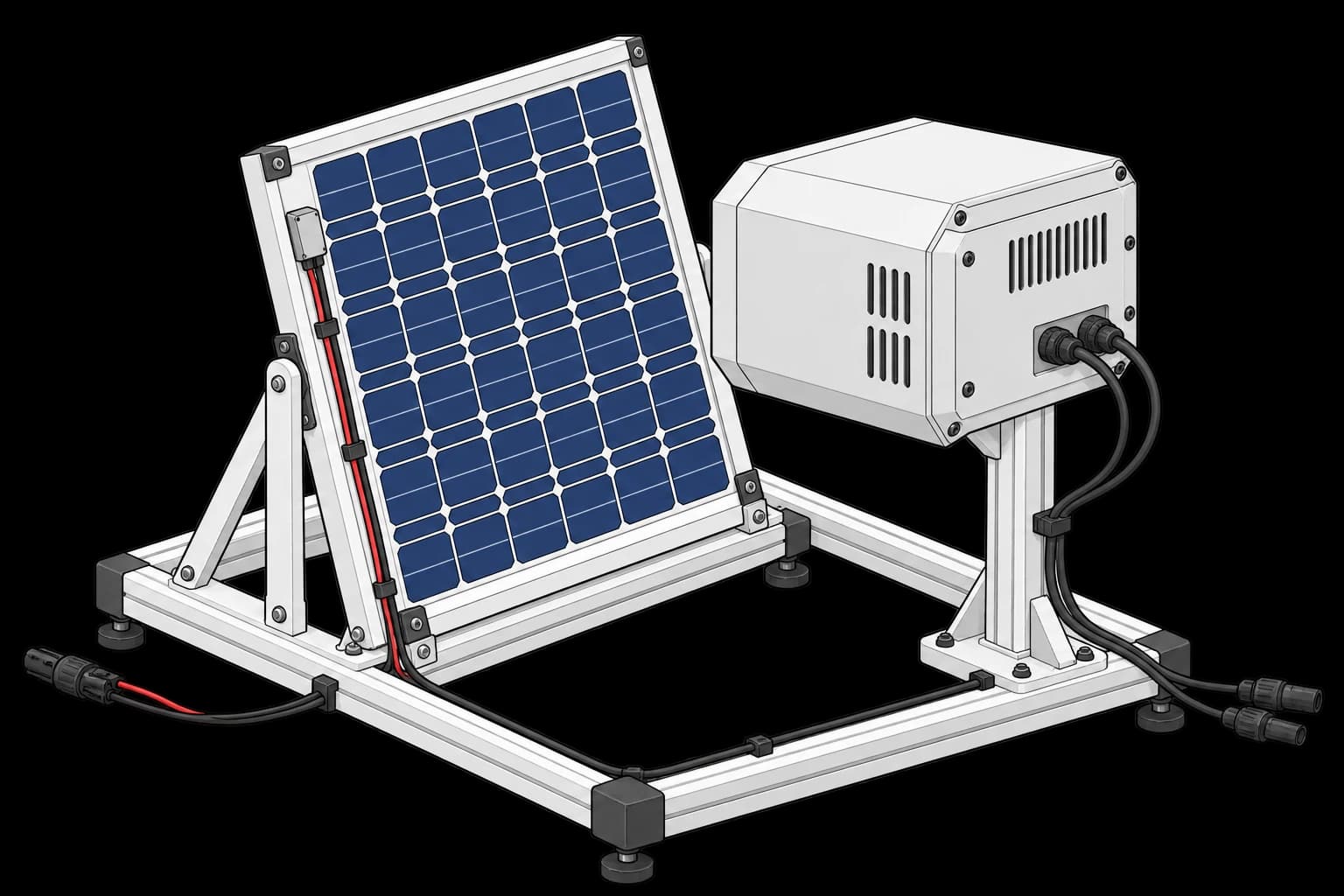
Solar panel facing an illumination head on a flash-test fixture

Solar Array Flash Test

Measure a solar array’s electrical response under a flash source.
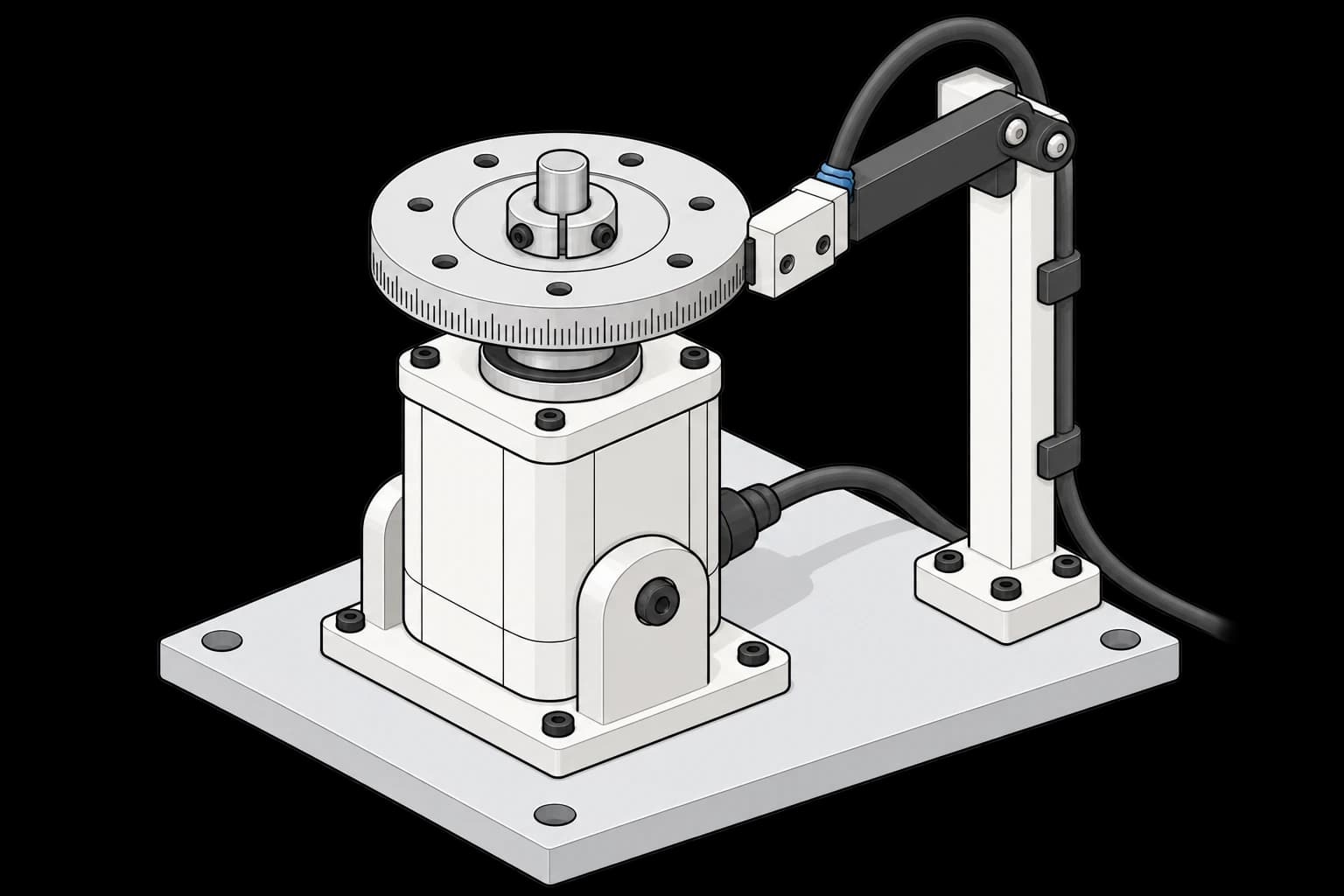
Motor shaft with a mounted encoder ring and a readhead facing the rim

Encoder and Commutation Calibration

Align encoder readings and motor commutation before assembly.
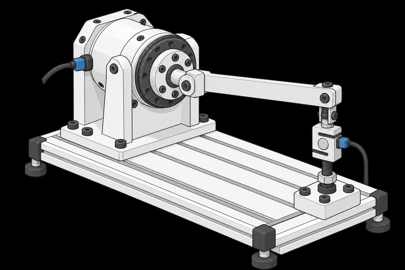
Joint actuator with a radial lever and a perpendicular loading screw and load cell

Joint Module Backlash and Stiffness Test

Measure joint play and stiffness under load.
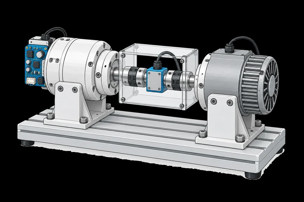
Actuator and load motor coupled on a guarded dynamometer test bed

Actuator End-of-Line Dyno Test

Measure joint torque, efficiency and ripple before robot assembly.
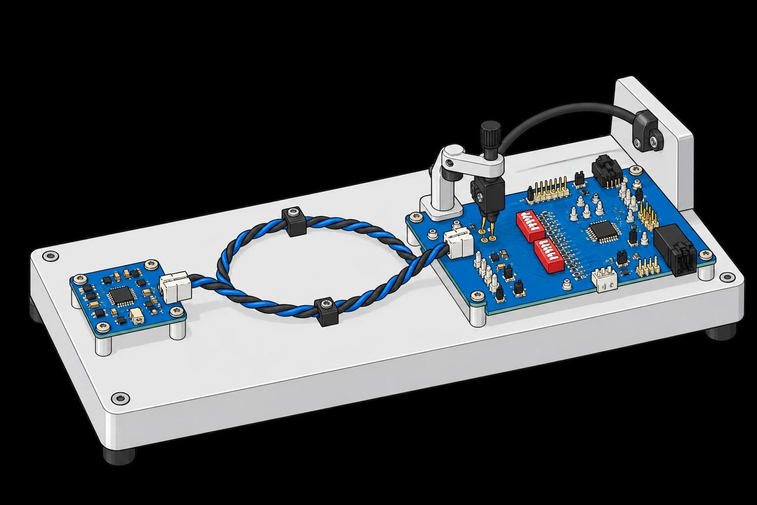
Cell-monitoring board and host bridge connected by a twisted-pair harness in a probe fixture

BMS Daisy-Chain Signal Integrity

Verify communication through the battery monitoring chain.
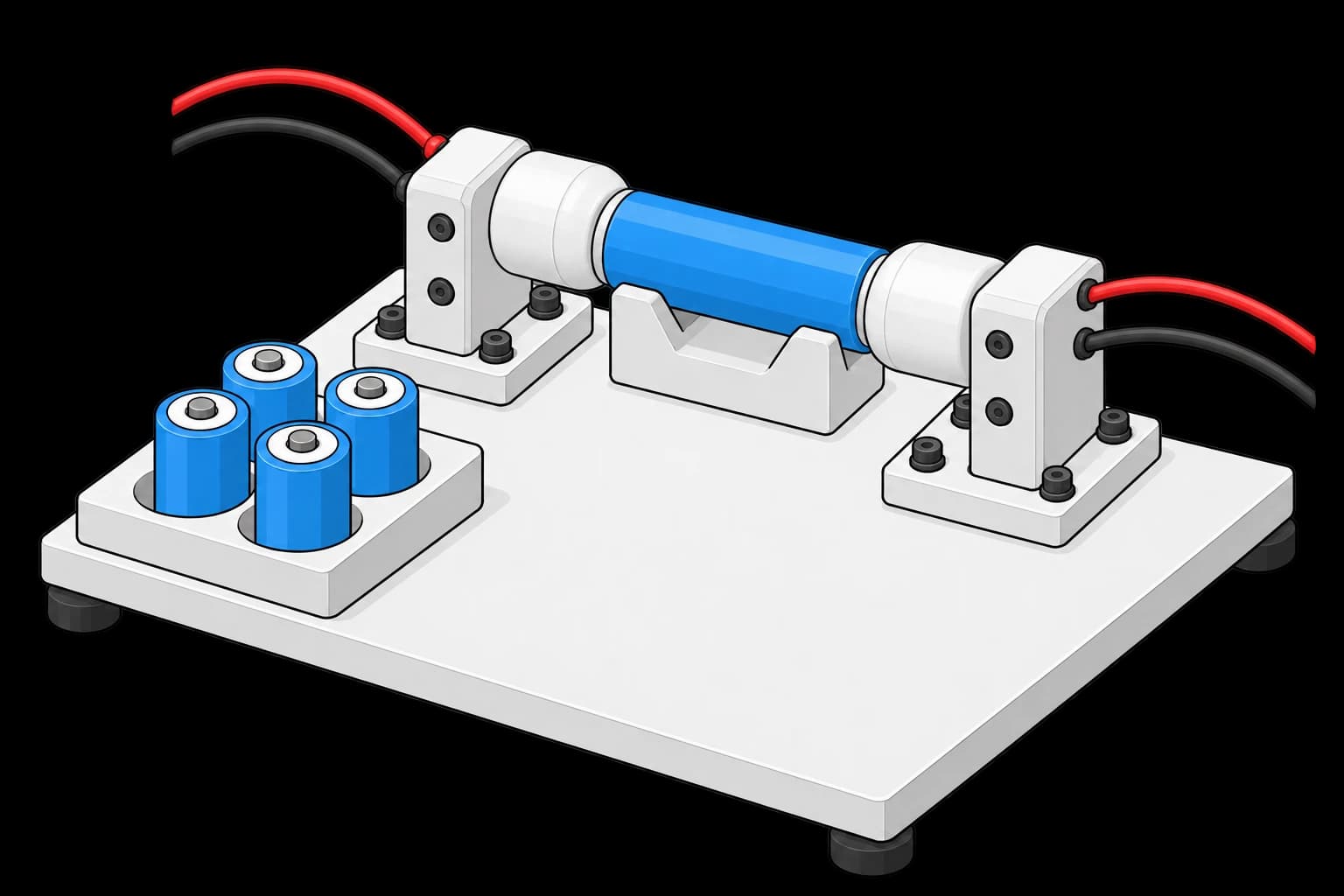
Cylindrical cell in an insulated four-wire contact fixture beside a waiting tray

Cell Incoming Inspection

Screen incoming battery cells before pack assembly.
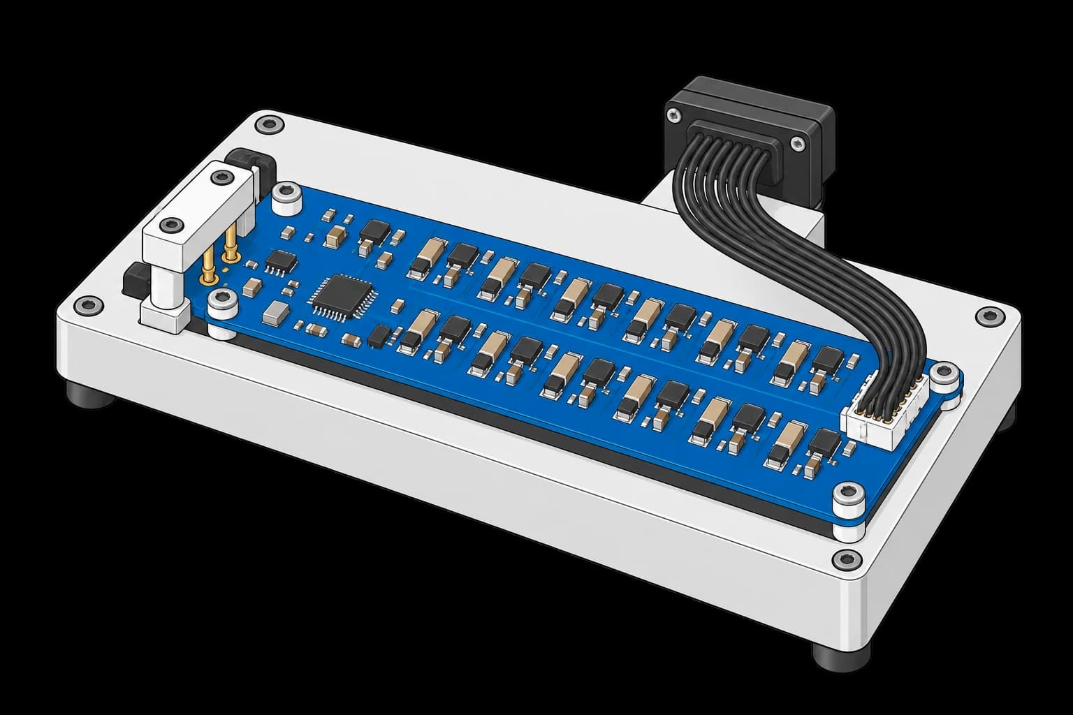
BMS board with two rows of balancing components and a cell-sense test harness

BMS Cell Balancing Verification

Check that the BMS balances cells as expected.
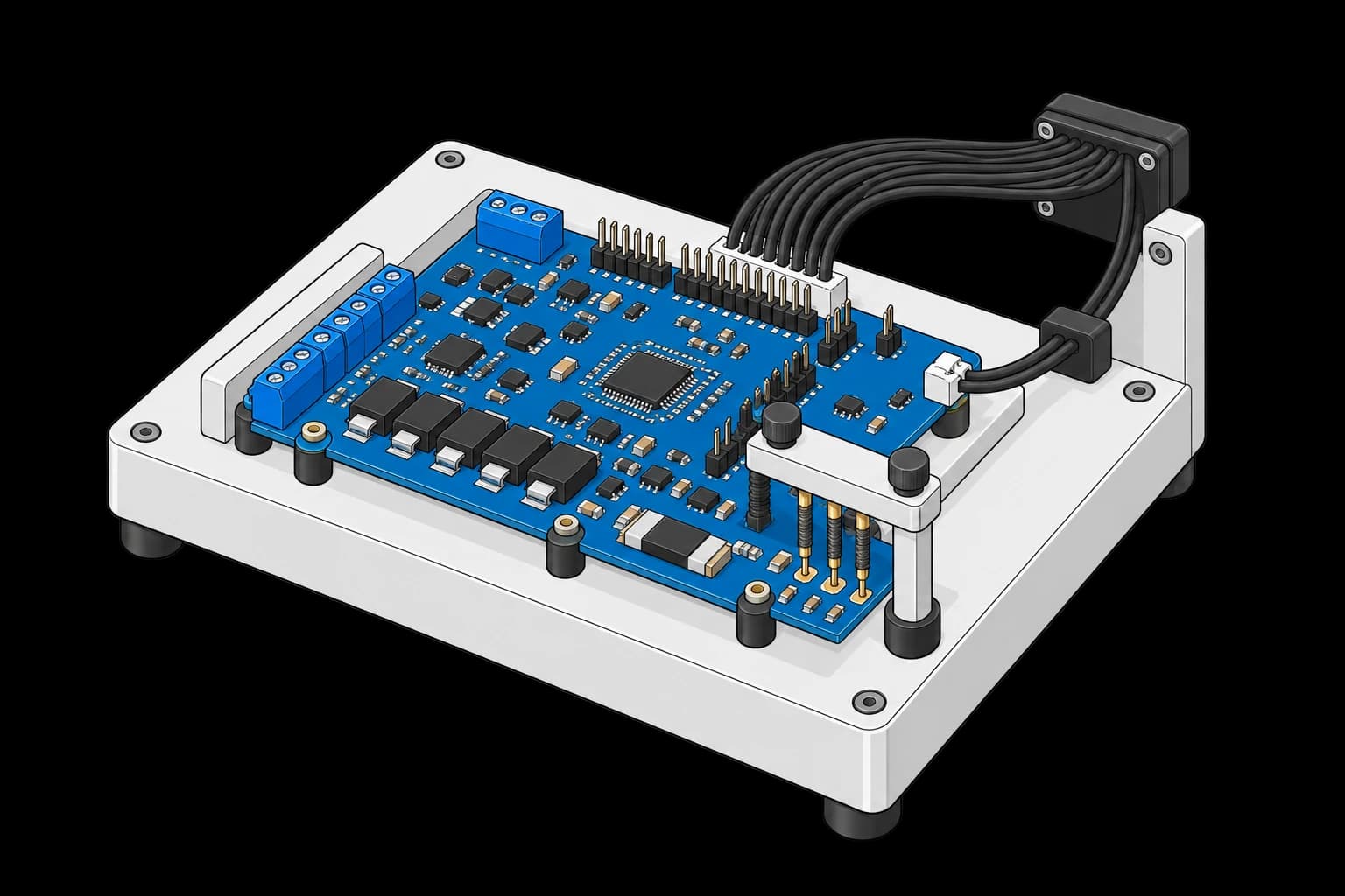
BMS protection board in a fixture with cell-sense wiring and protection-test probes

BMS Protection Trip Verification

Verify the BMS responds to protection limits.
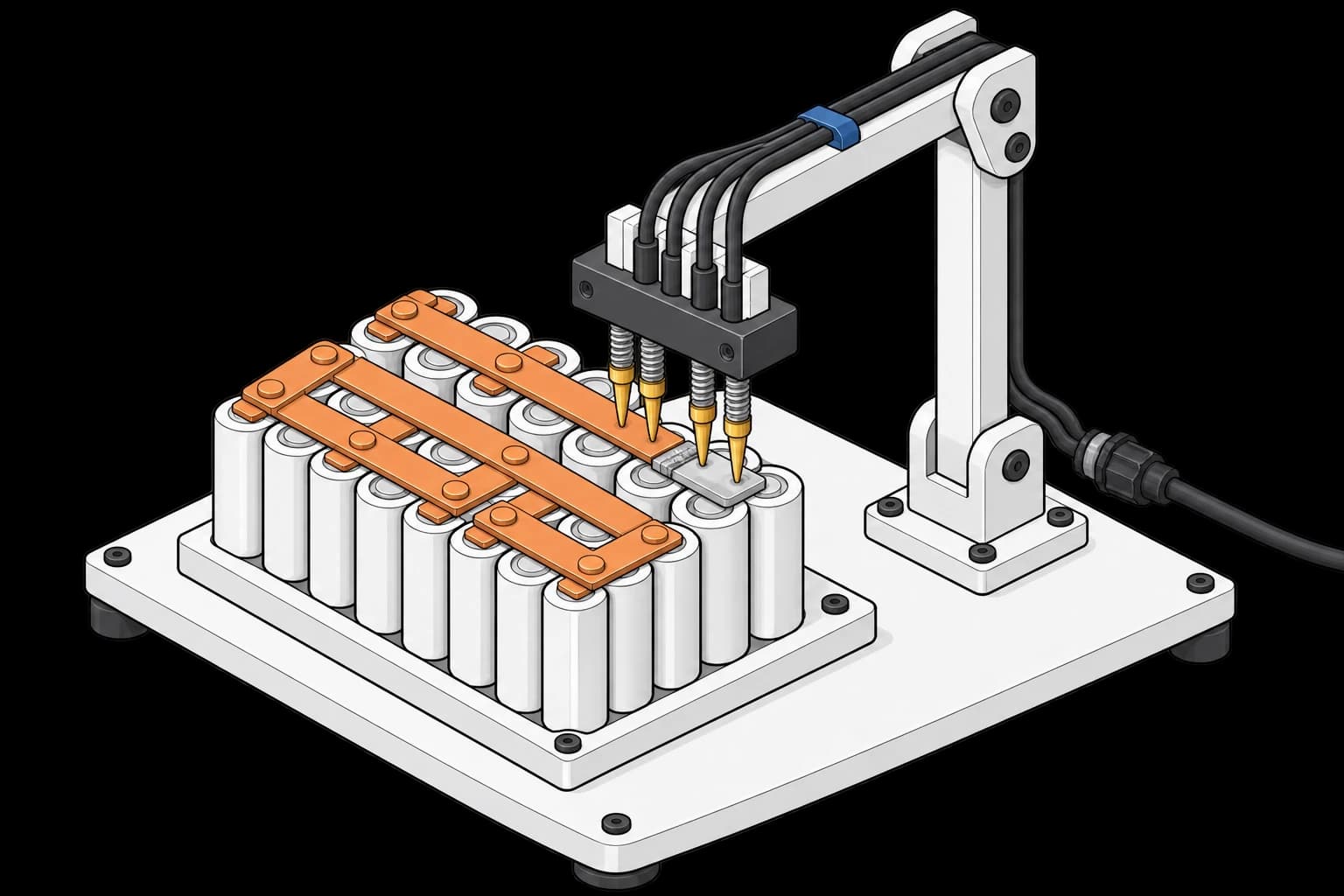
Four spring probes spanning a busbar joint on an insulated cell-module fixture

Weld and Busbar Resistance

Measure resistance across battery interconnects and welds.
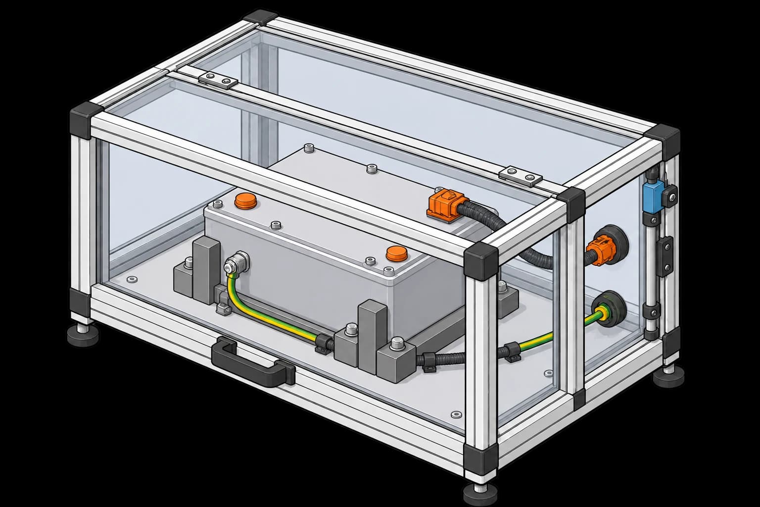
Battery pack secured inside a closed interlocked electrical-test enclosure

Pack EOL Hipot and Insulation Test

Check pack insulation and dielectric strength before release.
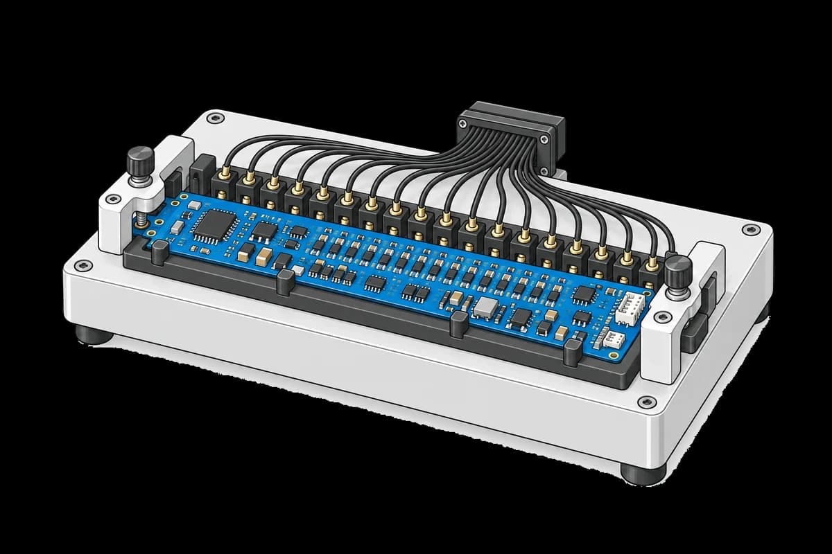
Battery management board in a fixture with individual cell-sense contacts

BMS Cell Simulator Functional Test

Verify cell readings, channel order and open-wire detection on a BMS.
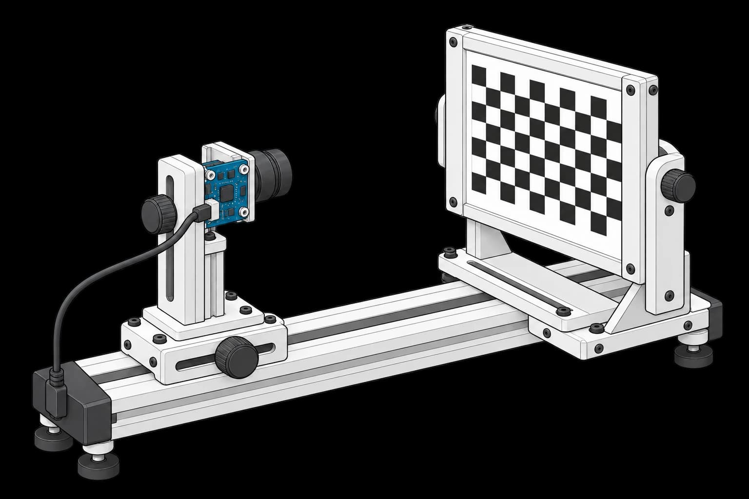
Camera module on an adjustable rail facing a checkerboard target

Camera Module Intrinsic Calibration

Calibrate lens distortion and camera geometry.
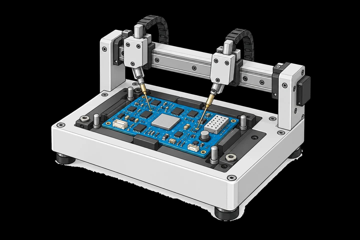
Two flying probes contacting a blue circuit board on a test bed

In-Circuit Test with Flying Probe

Check board connections and components with a flying probe.
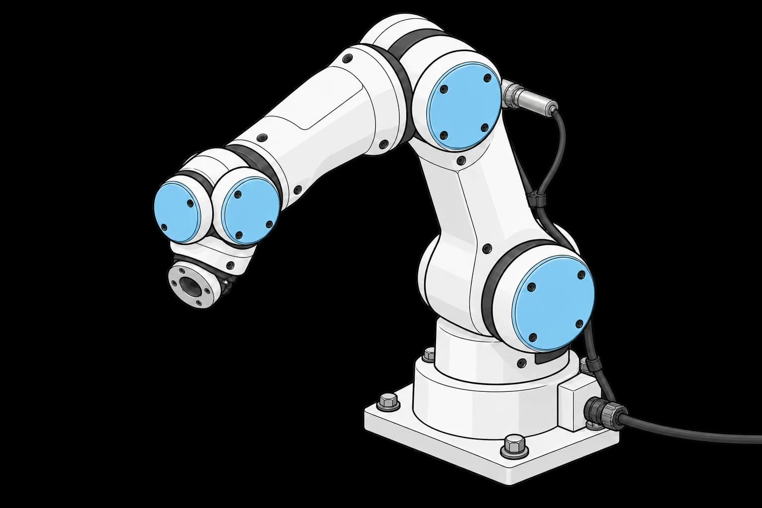
Robot arm with an electronic mastering probe fitted to a joint housing

Joint Encoder Zeroing and Mastering

Establish a repeatable reference position for each robot joint.
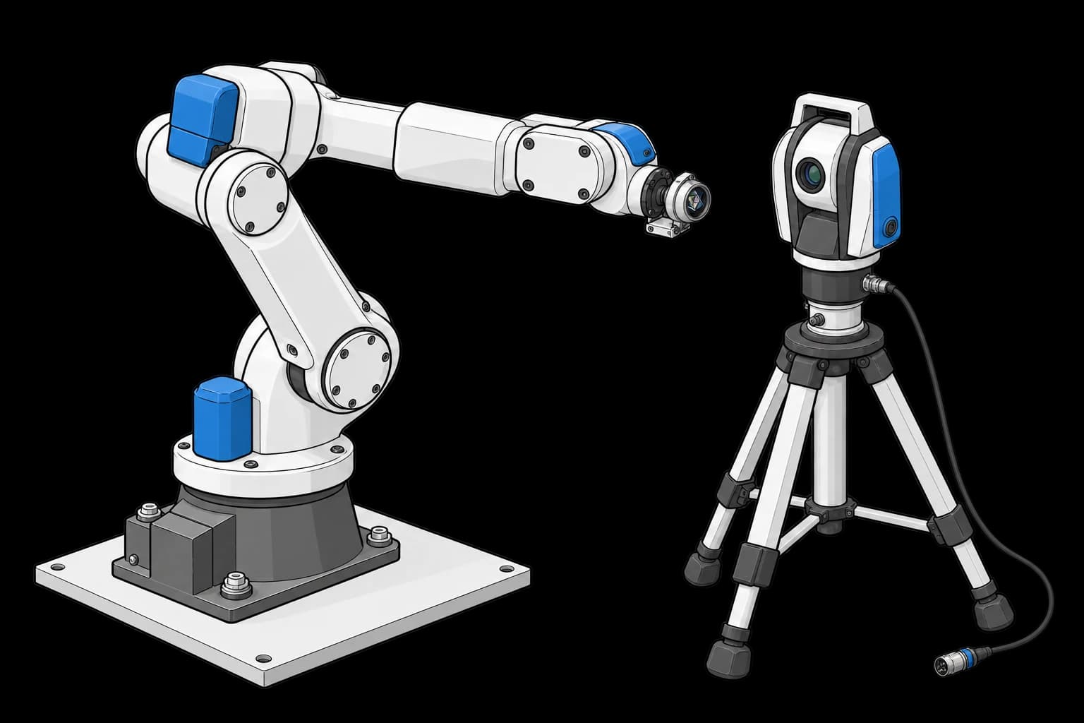
Robot wrist reflector opposite a laser tracker on a tripod

ISO 9283 Repeatability and Accuracy Test

Measure robot positioning accuracy and repeatability.

Open thermal chamber holding blue circuit boards on a rack

Board-Level Burn-In Stress Testing

Screen boards for early failures under sustained thermal stress.
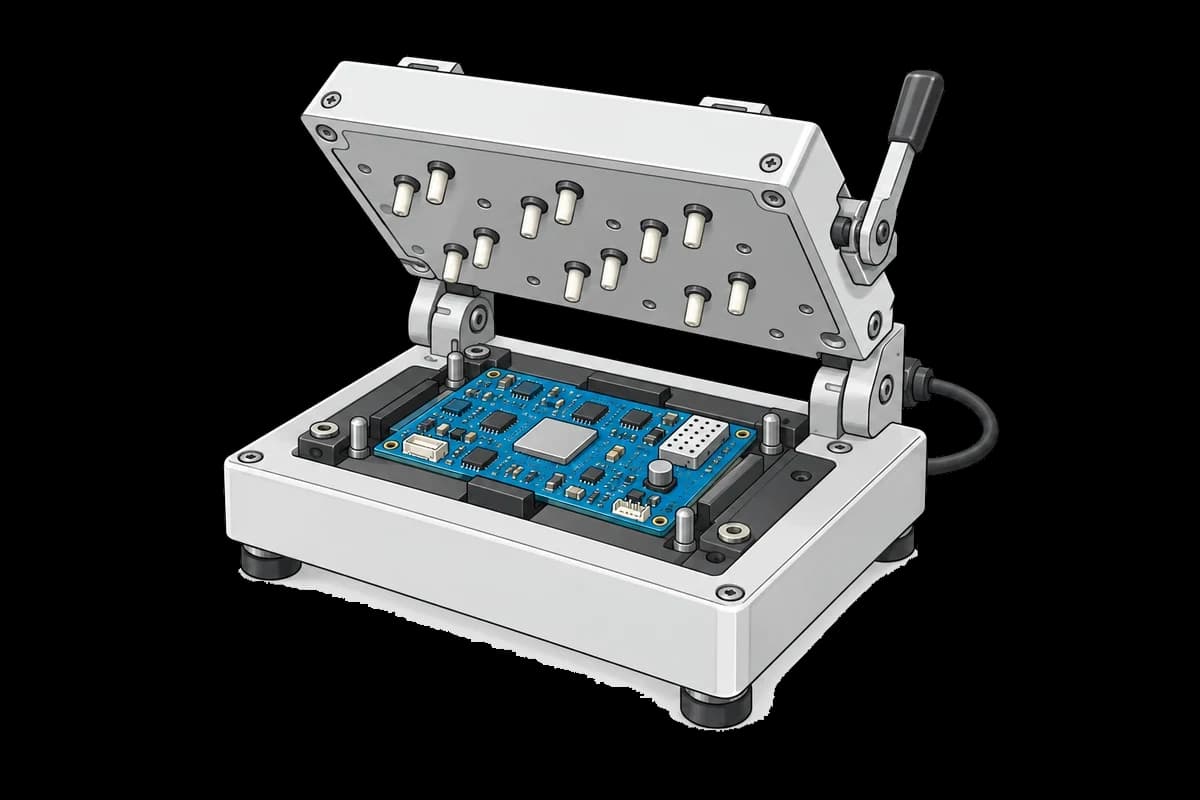
Open clamshell fixture holding a blue circuit board above its test contacts

Boundary Scan JTAG Test

Check board connectivity through the JTAG scan chain.
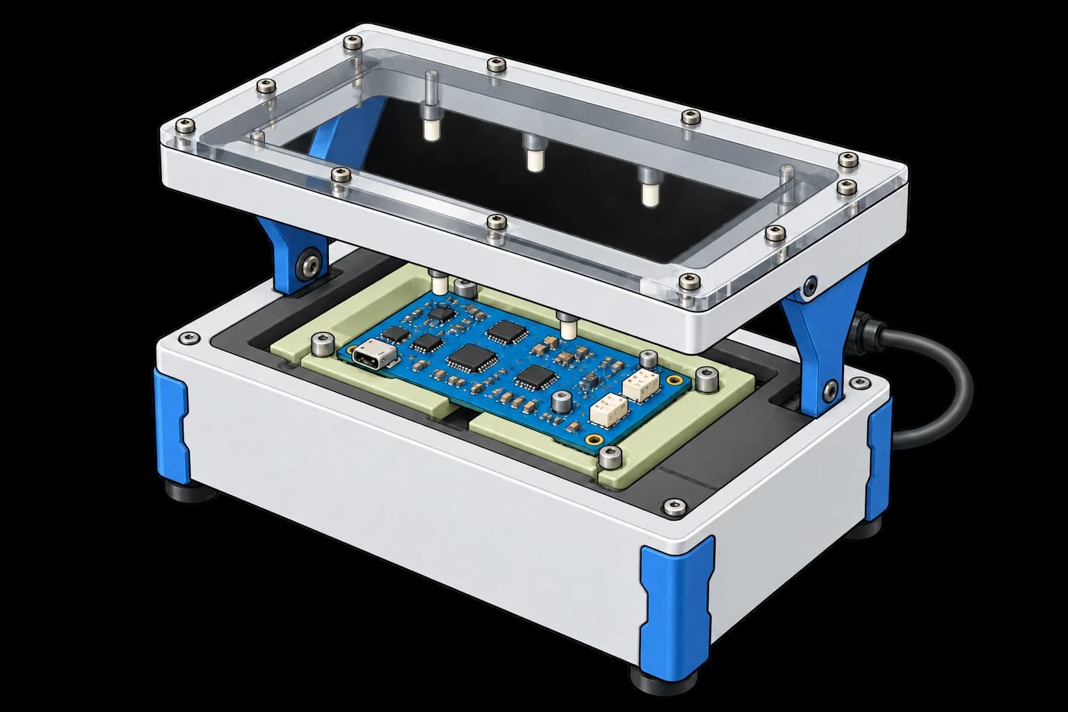
Blue circuit board in a manual test fixture beneath a raised transparent pressure plate

Functional Test Fixture (FCT)

Power and exercise a populated board through a pogo-pin fixture.

Open clamshell fixture holding a blue circuit board above its test contacts

MCU Programming and Serialization

Program each controller and record its unique identity.
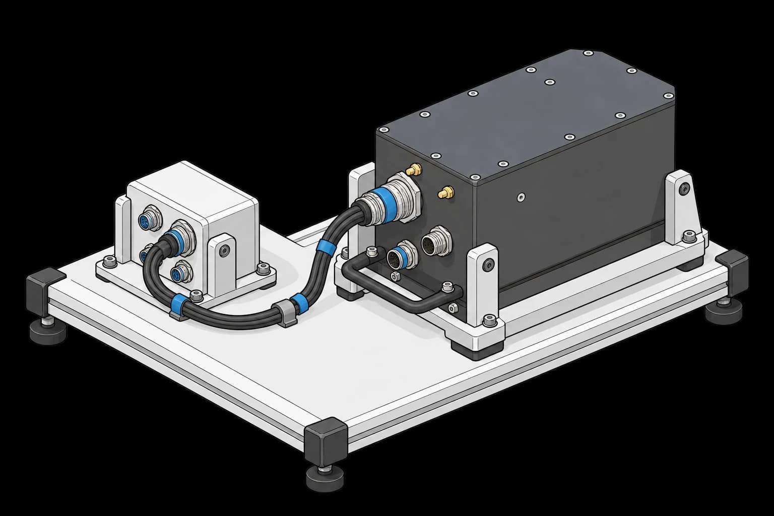
Avionics line-replaceable unit secured to a fixture with connector harnesses

ARINC 429 LRU Acceptance Test

Verify an avionics unit’s ARINC 429 communication.
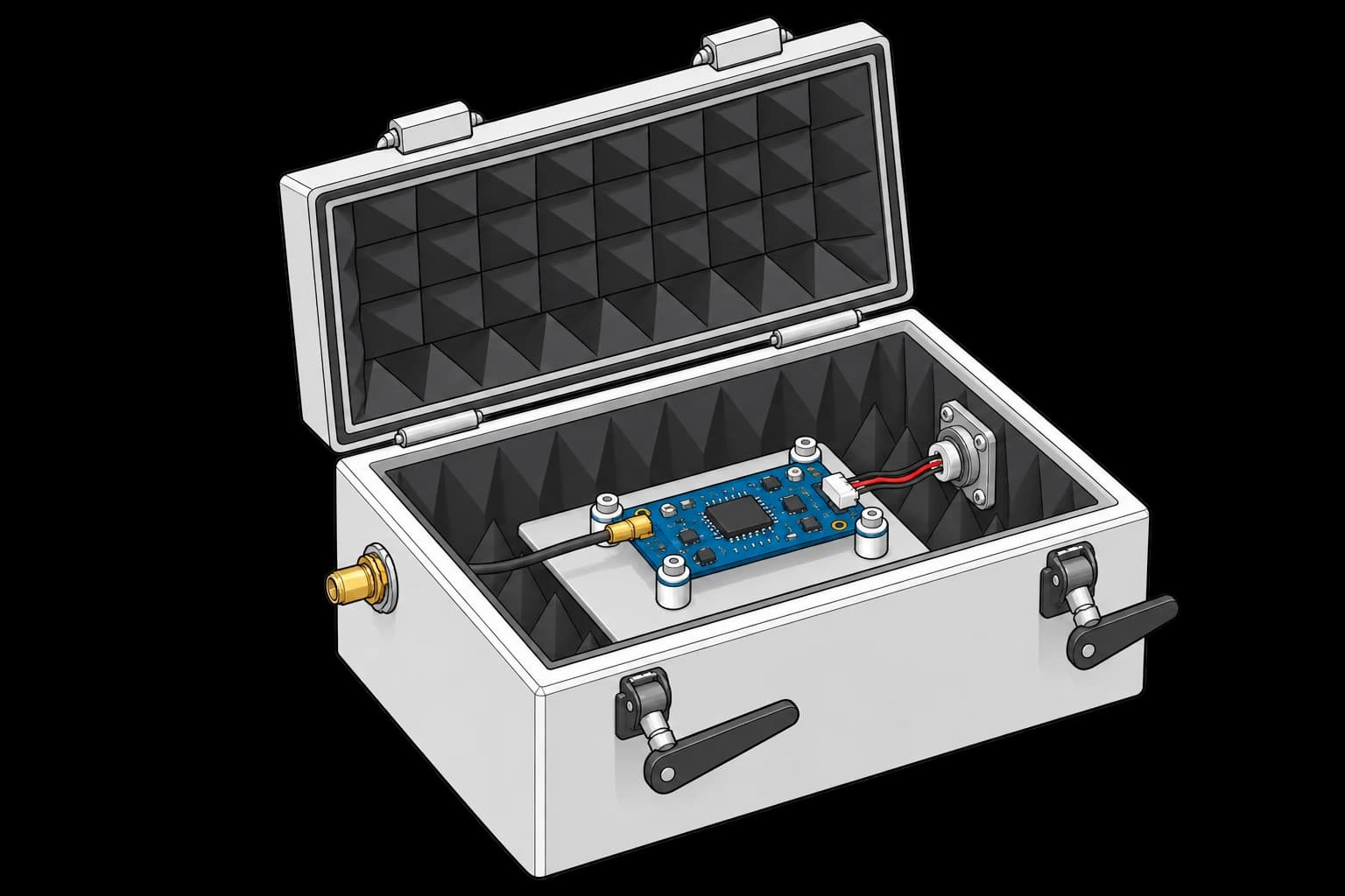
GNSS receiver board with coax and power connections inside an open RF shield box

GNSS Receiver Sensitivity Verification

Check receiver performance as the satellite signal weakens.
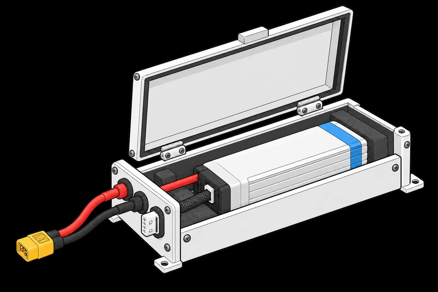
LiPo battery pack secured in an enclosure with separate power and sleeved balance leads

LiPo Battery Discharge and IR Profiling

Measure battery capacity and internal resistance under load.
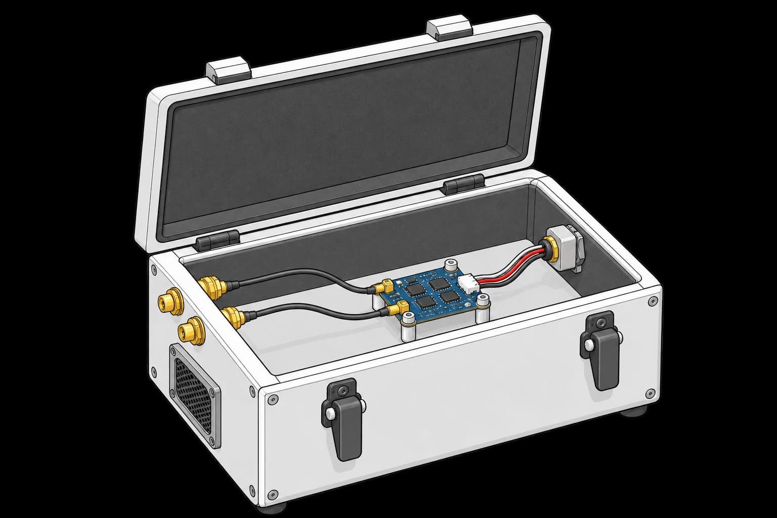
RC receiver with two coax connections and an electrical harness inside an RF shield box

RC Link RSSI vs Range Verification

Compare radio link strength across the operating range.

Propeller-free motor on a rigid fixture with accelerometer and optical tachometer

Motor Balance and Vibration Signature

Measure motor vibration across operating speeds.
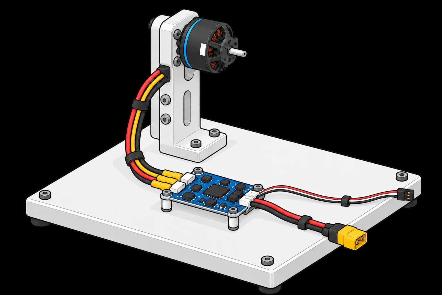
ESC board connected to a propeller-free motor with separate power and control leads

ESC Throttle-to-RPM Characterization

Map throttle commands to motor speed through the controller.
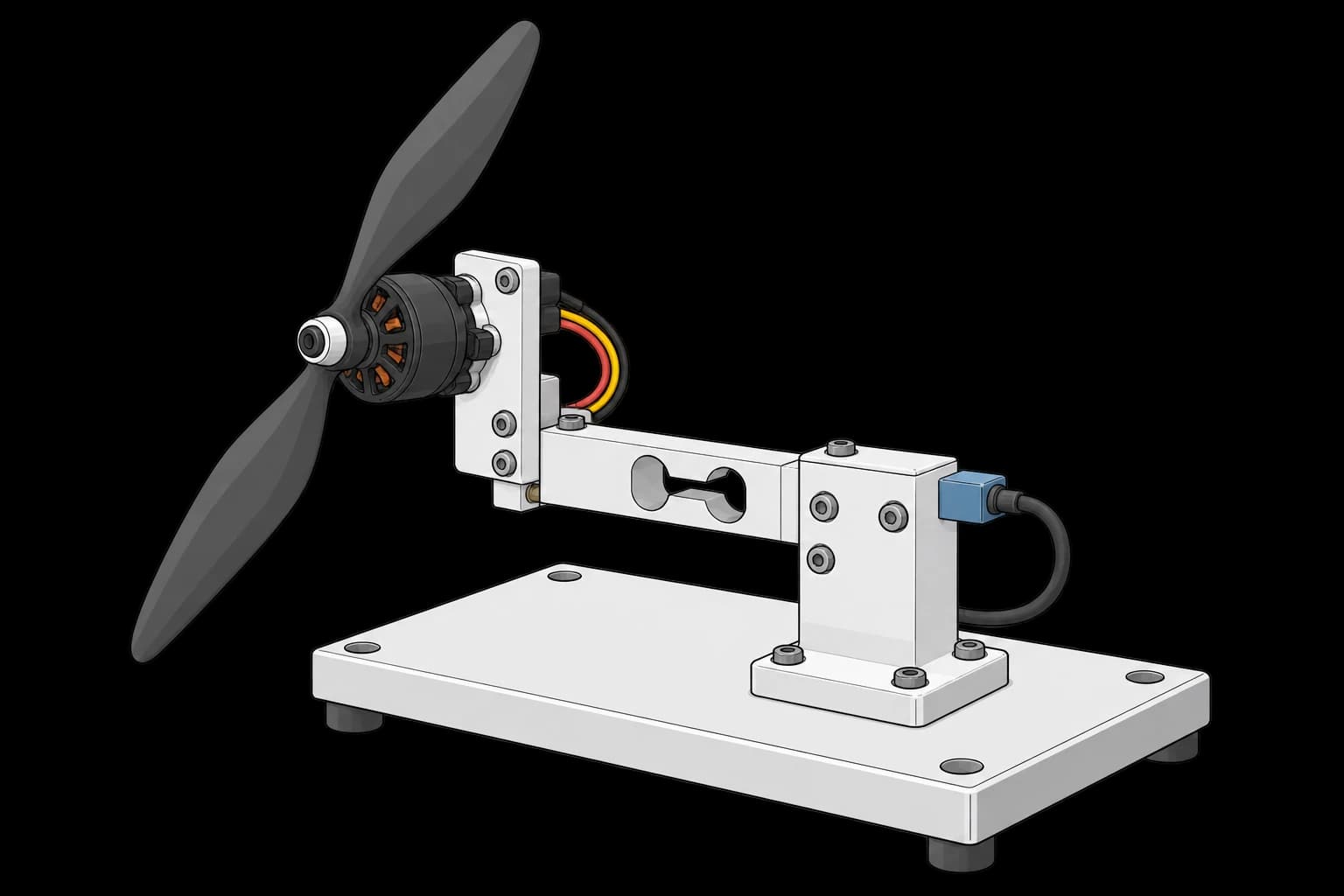
Motor and propeller mounted through a force transducer on a thrust-test fixture

Propeller Thrust and Efficiency Curve

Measure propeller thrust and efficiency across operating points.
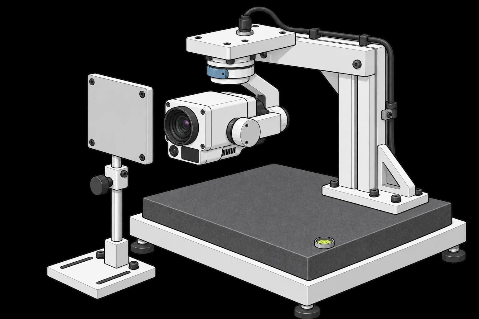
Three-axis camera gimbal suspended over a reference plate opposite a target

Gimbal Three-Axis Alignment Calibration

Align all three gimbal axes to a common reference.
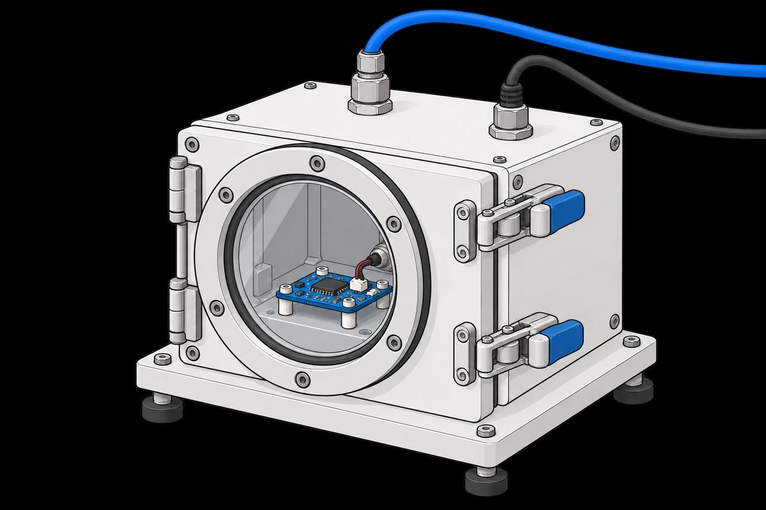
Sensor board inside a sealed pressure chamber with pneumatic and electrical feedthroughs

Barometric Altimeter Pressure Calibration

Calibrate altitude readings against controlled pressure.
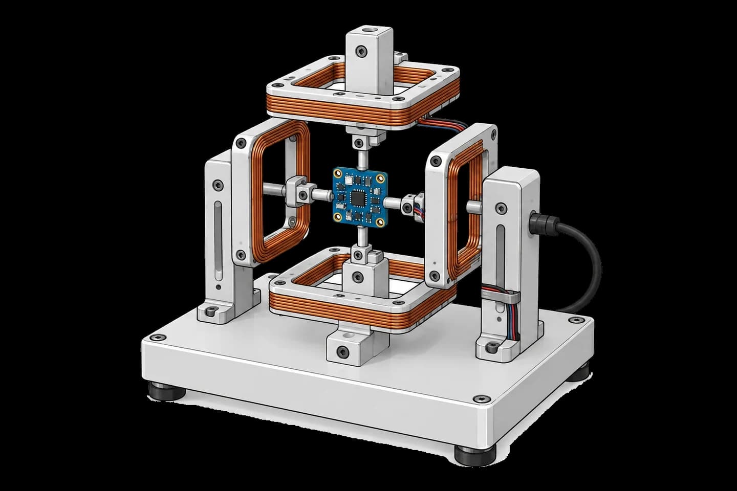
Blue sensor board in a rotation jig surrounded by copper calibration coils

Magnetometer Hard/Soft Iron Calibration

Compensate magnetic readings for nearby materials.
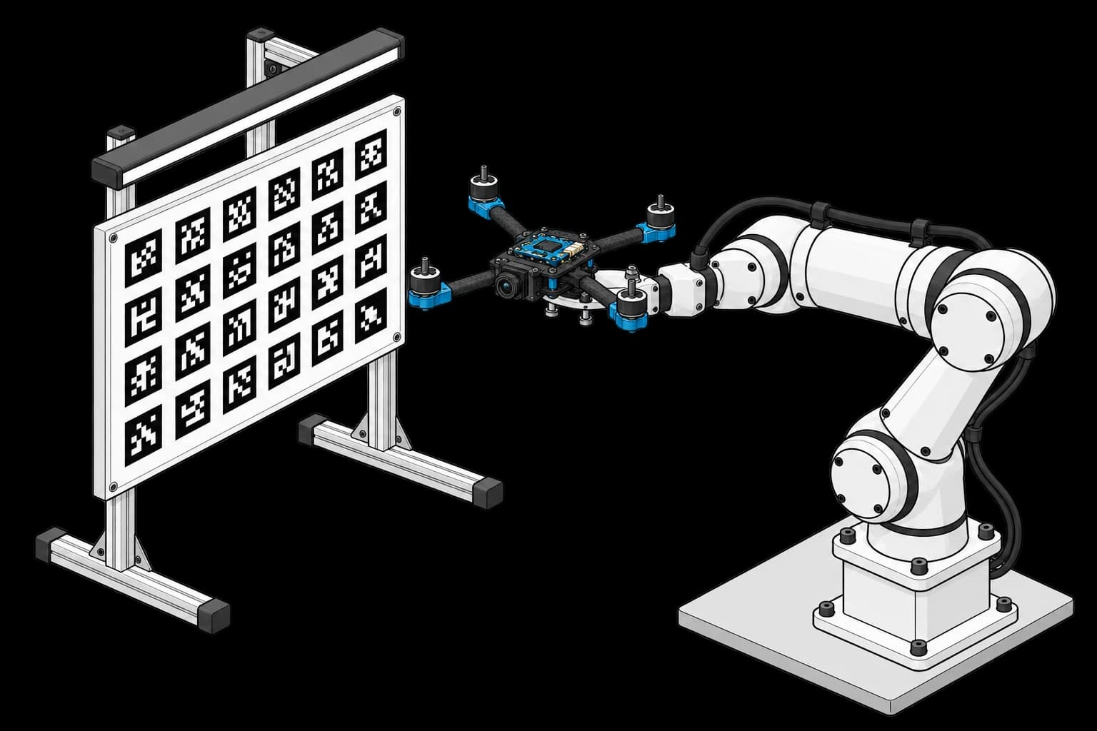
Four-arm quadcopter without propellers mounted on a robot opposite an AprilTag target

Camera-IMU Extrinsic Calibration

Align the camera and inertial sensor coordinate frames.
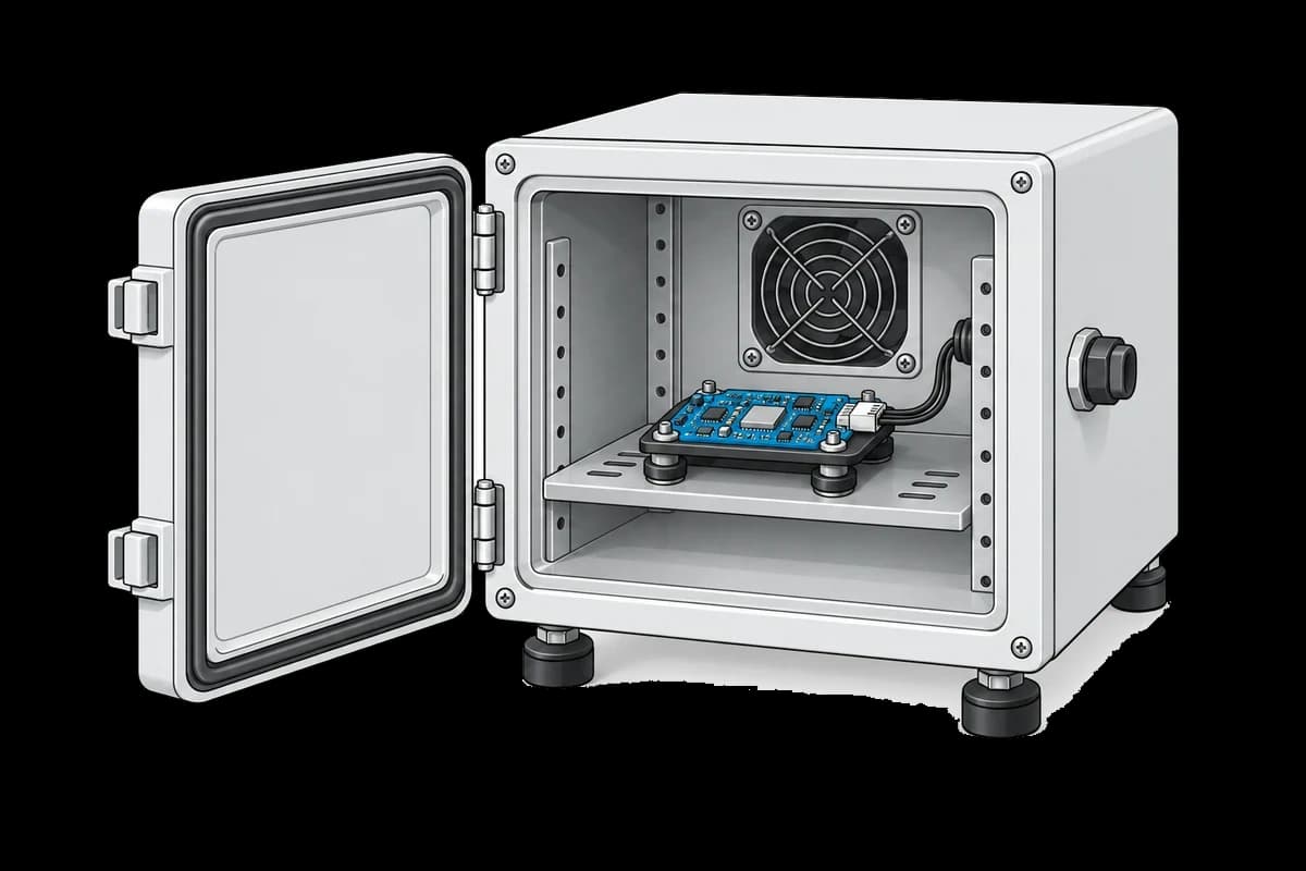
Sensor board mounted inside an open temperature chamber

IMU Thermal Calibration

Cycle temperature and compensate each sensor’s measurement drift.

Run your first test in minutes