
Introduction
Solar Array Flash Test Overview
A satellite's power budget is written against the power its panels deliver at 25 °C under one solar constant of the AM0 spectrum, and the flash test is where that number is measured on every flight panel. A large-area pulsed solar simulator (a LAPSS) fires a xenon pulse of a couple of milliseconds at the panel while an electronic load sweeps each string from short circuit to open circuit; the panel never heats, and a reference cell in the test plane reads the same pulse so every curve can be corrected to the standard conditions whatever the lamp delivered. The test finds cracked cells, open interconnects, shorted or open bypass diodes, strings wired wrong, insulation to the substrate that has broken down, and, when repeated after thermal cycling and vibration, the degradation those environments caused.
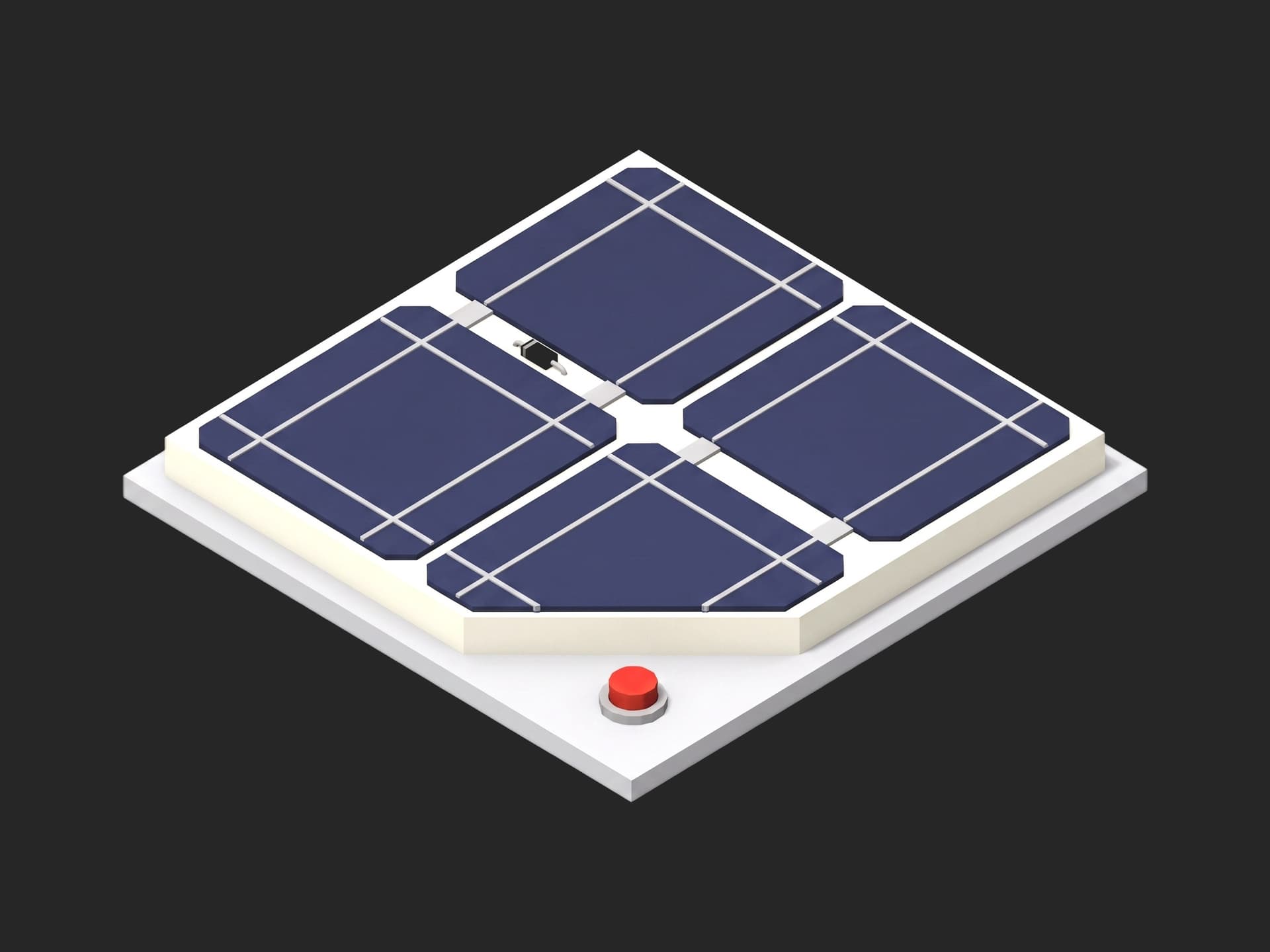
One corner of the panel: the cells, their interconnects, and the bypass diode that carries the string current around a shaded or failed cell group.
The standard is ECSS-E-ST-20-08C Rev.2, the photovoltaic assembly standard. Its Table 5-2 gives the acceptance sequence for a flight panel: visual inspection, health check, capacitance, electrical performance, bake-out, thermal cycling, and the same again after; its clause 10 defines the reference cells, a primary standard calibrated on a balloon or in orbit and secondary working standards traced to it; its example health-check values are insulation resistance above 100 MΩ at 500 V between circuit and substrate (ECSS-E-ST-20-08C Rev.2). The flasher itself is characterised in the JPL LAPSS work and the Spectrolab LAPSS II datasheet: ±1 % pulse-to-pulse, ±2 % uniformity over the test plane, 0.025 % voltage resolution. The power limit is not in the standard; it is project-defined in the PVA specification, and the test accuracy must be smaller than the calibration loss factor the power budget carries.
Test Purpose
The procedure records one electrical fingerprint per panel:
- Lamp intensity and pulse-to-pulse repeatability from three pulses on the reference cell alone, and the panel temperature
- Health check: insulation resistance at 500 V on three paths and the panel capacitance
- One flash per string, the IV curve corrected to 25 °C and 1 SC AM0, with Isc, Voc, Pmax and fill factor per string, the panel Pmax and the string match
- Forward drop of every bypass diode at string current
- Lamp pulses consumed, logged against the flash tube's life
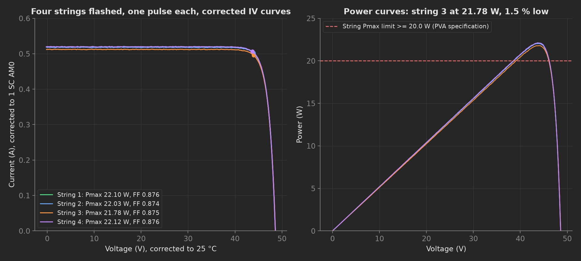
The mock panel's four strings after correction: 22.0 to 22.1 W on three of them, 21.8 W on string 3 where one cell sits at the bottom of its grade, all above the 20 W specification and within 1.5 % of each other.
The framework mechanics on show are four curves in one measurement with aggregations and limits on each, a physics correction in utils/ shared by the phases and the charts, a reference instrument validated in setup: on three pulses, a consumable tracked on the unit, and scalar limits taken from a standard's example values.
Equipment & Setup
To run this acceptance test on a panel line, the following are required:
- A large-area pulsed solar simulator with a test plane larger than the panel, and its reference cell holder in the plane
- A secondary standard reference cell of the same cell technology as the panel, with a calibration certificate traced to a primary standard
- An IV load fast enough to sweep a string during the pulse, triggered by the flasher
- A megohmmeter at 500 V DC and an LCR meter for the health check
- Thermocouples on the panel substrate
- The Device Under Test (DUT): a flight panel on its handling frame, in the test plane, at room temperature
- A TofuPilot Framework procedure to sequence the pulses, correct the curves and validate the limits
- The TofuPilot Dashboard to keep the before-and-after record every environmental test is judged against
Hardware Components
Pulsed Solar Simulator
The Spectrolab LAPSS II is the reference instrument: a 2 ms xenon pulse over a test plane of several metres, pulse-to-pulse repeatability better than ±1 %, spectral match to AM0 through filtering, voltage resolution 0.025 %. JPL's installation report (JPL Publication 93-22) measured ±2 % uniformity and ±0.3 % repeatability on their unit. Angstrom Designs and Pasan build comparable flashers. Whatever the lamp, the reference cell in the plane on every pulse is what makes the number traceable: the lamp's intensity on that pulse is the reference cell's short-circuit current over its calibrated value.
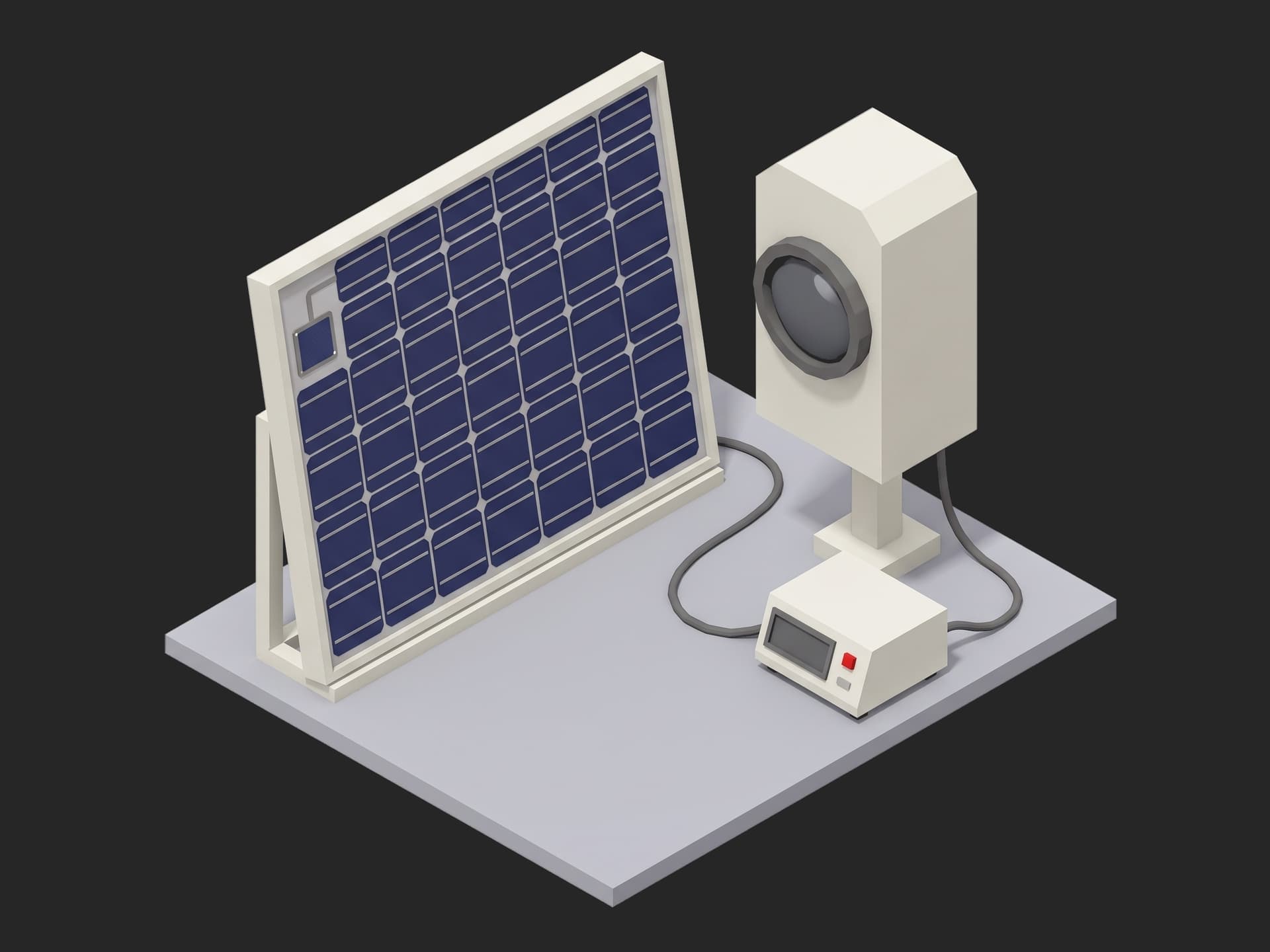
A single-panel station: the panel on its frame in the test plane, the reference cell on its tab in the same plane, the lamp on its post, the IV load and the health-check instruments on the right.
Reference Cell
ECSS-E-ST-20-08 clause 10 defines the chain: a primary standard calibrated under the extraterrestrial spectrum (balloon or orbit), secondary working standards of the same cell technology traced to it, recalibrated on a schedule. The reference cell's calibrated short-circuit current at 1 solar constant AM0 and 25 °C is the number every correction in this template divides by; it lives in the recipe and on the certificate, and the setup phase records which cell was in the plane.
Health-Check Instruments
A megohmmeter or a Keysight B2985 electrometer at 500 V DC for the circuit-to-substrate, adjacent-strings and thermal-sensor-to-substrate paths; an LCR meter for the panel capacitance, a dielectric health number that moves when the substrate insulation is damaged; type-T thermocouples on the substrate for the correction.
Where the Limits Come From
ECSS-E-ST-20-08 gives the sequence and the health-check example values; the electrical limits are the project's PVA specification:
| Test | Limit | Basis |
|---|---|---|
| Pulse-to-pulse repeatability | ≤ 1.0 % over three pulses | flasher datasheet ±1 % |
| Lamp intensity | 0.95 to 1.05 SC | correction valid range |
| Panel temperature | 18 to 30 °C | correction valid range, thermocouple on the substrate |
| Insulation resistance | ≥ 100 MΩ at 500 V | ECSS-E-ST-20-08 example values |
| Capacitance | 80 to 160 nF | this panel's build, ±33 % |
| String Pmax | ≥ 20.0 W | PVA specification: 92.6 % of 21.6 W nominal |
| Fill factor | ≥ 0.80 | 3J cells at 0.85 typical; a cracked cell or a bad interconnect lowers it |
| Panel Pmax | ≥ 80 W | four strings at the specification |
| String match | ≤ 3 % | cells graded to match within a panel |
| Bypass diode Vf | 0.5 to 1.2 V at string current | open reads the cells' reverse breakdown, short reads zero |
The thermal-cycling acceptance criterion in the standard is written as a maximum Iop increment per the specification and "fewer than 2 % of cells cracked, or one cell, whichever is higher"; this template's before-and-after comparison is the number that criterion is applied to.
Test Procedure
Overview
The procedure maps the acceptance onto the framework's three stages. The reference pulses live in setup: so no panel curve is recorded under a lamp out of adjustment or on a warm panel. Shorting the panel lives in teardown: so it is never left at open circuit under the lamp.
- Setup: three reference pulses, lamp intensity, repeatability, panel temperature.
- Main: insulation resistance on three paths at 500 V, capacitance.
- Main: one flash per string, corrected IV, Pmax, fill factor, panel Pmax, string match.
- Main: forward drop of every bypass diode.
- Teardown: panel shorted, pulses logged.
Every metric validates against limits declared in procedure.yaml, and results stream to TofuPilot as the panel's acceptance record.
Why TofuPilot Framework?
TofuPilot Framework is a YAML + Python test framework built for hardware manufacturing. Instead of writing all your test logic, measurements, and limits inside Python code, you describe what the test does in a procedure.yaml file, and how in small Python phase files. The framework handles:
- Automatic Python environment management (via
uv) - Operator UI (no frontend code needed)
- Measurement validation and live charts
- Process isolation between phases and equipment plugs
Project Structure
You can find the full source on GitHub. The FlashBench plug is a mock of the flasher, the reference cell, the IV load, the megohmmeter, the LCR meter and the thermocouples together, synthesizing a healthy four-string panel at 23 °C with one string 1.5 % low, so the procedure runs end-to-end without a flasher or a panel connected.
tofupilot run .For CI or bench automation, the same run executes headless:
tofupilot run . --no-tui --no-kiosk --jsonThe Procedure File
procedure.yaml declares the unit, the bench plug, and the three stages with every measurement and limit:
name: Solar Array Flash Testversion: 0.1.0description: Electrical acceptance of a smallsat solar panel under a large-area pulsed solar simulator. Reference cell pulses for lamp intensity and repeatability, insulation resistance at 500 V and capacitance, one flash per string with the IV curve corrected to 25 C and 1 SC AM0, string match, every bypass diode's forward drop.unit: auto_identify: true serial_number: description: "Scan the panel's substrate label" placeholder: "SA-WING-000" pattern: "^SA-WING-\\d{3}$" default_value: "SA-WING-047" part_number: default_value: "SA-4S18-3G30" batch_number: default_value: "CELL-LOT-2026-19"plugs: - name: Flash Bench description: "Pulsed solar simulator with reference cell, IV load, megohmmeter, LCR meter, thermocouples (mock LAPSS II-class, one plug per bench)" python: plugs.flash_bench:FlashBench key: benchsetup: - name: Reference Check key: reference_check python: phases.reference_check measurements: - name: Pulse Repeatability key: pulse_repeat_pct unit: "%" description: Spread of three reference-cell pulses; the flasher's own pulse-to-pulse figure is +-1 %. validators: - {operator: "<=", expected_value: 1.0} - name: Lamp Intensity key: lamp_intensity_sc unit: SC description: Solar constants delivered, from the reference cell; the correction handles 0.95 to 1.05, outside it the lamp is out of adjustment. validators: - {operator: ">=", expected_value: 0.95} - {operator: "<=", expected_value: 1.05} - name: Panel Temperature key: panel_temp_c unit: °C validators: - {operator: ">=", expected_value: 18.0} - {operator: "<=", expected_value: 30.0}main: - name: Health Check key: health_check python: phases.health_check measurements: - name: IR Circuit To Substrate key: ir_circuit_substrate_mohm unit: MΩ description: 500 V DC, ECSS-E-ST-20-08 example value greater than 100 MOhm at ambient. validators: - {operator: ">=", expected_value: 100.0} - name: IR Adjacent Strings key: ir_adjacent_strings_mohm unit: MΩ validators: - {operator: ">=", expected_value: 100.0} - name: IR Sensor To Substrate key: ir_sensor_substrate_mohm unit: MΩ validators: - {operator: ">=", expected_value: 100.0} - name: Capacitance key: capacitance_nf unit: nF description: Panel capacitance as a dielectric health number; it moves when the substrate insulation is damaged. validators: - {operator: ">=", expected_value: 80.0} - {operator: "<=", expected_value: 160.0} - name: Flash IV key: flash_iv python: phases.flash_iv depends_on: [health_check] timeout: 5m measurements: - name: IV Curves key: iv title: String IV curves corrected to 25 °C, 1 SC AM0 x_axis: legend: Voltage unit: V y_axis: - legend: String 1 key: string_1 unit: A aggregations: - type: pmax_w unit: W validators: - {operator: ">=", expected_value: 20.0} - type: isc_a unit: A - type: voc_v unit: V - type: fill_factor validators: - {operator: ">=", expected_value: 0.80} - legend: String 2 key: string_2 unit: A aggregations: - type: pmax_w unit: W validators: - {operator: ">=", expected_value: 20.0} - type: isc_a unit: A - type: voc_v unit: V - type: fill_factor validators: - {operator: ">=", expected_value: 0.80} - legend: String 3 key: string_3 unit: A aggregations: - type: pmax_w unit: W validators: - {operator: ">=", expected_value: 20.0} - type: isc_a unit: A - type: voc_v unit: V - type: fill_factor validators: - {operator: ">=", expected_value: 0.80} - legend: String 4 key: string_4 unit: A aggregations: - type: pmax_w unit: W validators: - {operator: ">=", expected_value: 20.0} - type: isc_a unit: A - type: voc_v unit: V - type: fill_factor validators: - {operator: ">=", expected_value: 0.80} - name: Panel Pmax key: panel_pmax_w unit: W validators: - {operator: ">=", expected_value: 80.0} - name: String Match key: string_match_pct unit: "%" description: Spread of string Pmax over the mean; strings in one panel are graded to match and a mismatch is a cell at the wrong grade or a damaged one. validators: - {operator: "<=", expected_value: 3.0} - name: Bypass Diodes key: bypass_diodes python: phases.bypass_diodes depends_on: [flash_iv] measurements: - name: Diodes key: diodes title: Forward drop of every bypass diode at string current x_axis: legend: Diode y_axis: - legend: Vf key: vf unit: V aggregations: - type: max_v unit: V validators: - {operator: "<=", expected_value: 1.2} - type: min_v unit: V validators: - {operator: ">=", expected_value: 0.5}teardown: - name: Release key: release python: phases.release measurements: - name: Pulses This Run key: pulses_this_run description: Lamp pulses consumed, logged against the flash tube's life.Framework features to notice:
- Four strings, one measurement. The
ivmeasurement carries one corrected curve per string on a common voltage axis, each with its ownpmax_w,isc_a,voc_vandfill_factoraggregations; the limits sit on Pmax and fill factor, the others are recorded for the trend. - Correction in
utils/.correct_to_stcandiv_metricslive in a module both the phase and the article's charts import, so the chart is the run. - The reference proves the lamp first. Three pulses in
setup:give the repeatability and the intensity; a lamp out of its window fails before a panel curve is recorded. - A consumable on the unit. The pulse count goes onto
unit.metadataand into a teardown measurement without a limit; the flash tube's life is a station number, not a panel number.
Reference Check
Three pulses on the reference cell alone. Their spread is the flasher's pulse-to-pulse repeatability, their mean over the calibrated value is the intensity the lamp delivers, and the panel thermocouple is read for the correction's validity window. The reference cell's identity goes onto the unit metadata:
import numpy as npfrom utils.recipe import PULSE_REPEAT_PCT_MAX, REFERENCE_CELL_ISC_Adef reference_check(measurements, bench, unit, log): """Setup: three pulses on the reference cell alone. Their spread is the flasher's pulse-to-pulse repeatability, their mean over the calibrated value is the intensity the lamp delivers; the panel temperature must sit in the window the correction is valid for.""" isc = np.array([bench.reference_pulse()["isc_a"] for _ in range(3)]) spread = 100.0 * (isc.max() - isc.min()) / isc.mean() measurements.pulse_repeat_pct = float(spread) measurements.lamp_intensity_sc = float(isc.mean() / REFERENCE_CELL_ISC_A) measurements.panel_temp_c = bench.panel_temperature_c() unit.metadata["reference_cell"] = "WS-2026-07, secondary standard" log.info(f"Panel {unit.serial_number}: lamp {isc.mean() / REFERENCE_CELL_ISC_A:.4f} SC, pulse spread {spread:.2f} % (limit {PULSE_REPEAT_PCT_MAX}), panel {measurements.panel_temp_c} C")Health Check
The ECSS health check: insulation resistance at 500 V DC from the circuit to the substrate and from the thermal sensor to the substrate, at 250 V between adjacent strings, and the panel capacitance. Done here before the flash and repeated after every environment; a value that moved is a crack in the substrate insulation:
from utils.recipe import IR_TEST_Vdef health_check(measurements, bench, log): """Electrical health check per ECSS-E-ST-20-08: insulation resistance at 500 V on three paths and the panel capacitance. Done before the flash and repeated after environments; a value that moved is a crack.""" measurements.ir_circuit_substrate_mohm = bench.insulation_mohm("circuit_substrate", IR_TEST_V) measurements.ir_adjacent_strings_mohm = bench.insulation_mohm("adjacent_strings", 250) measurements.ir_sensor_substrate_mohm = bench.insulation_mohm("sensor_substrate", IR_TEST_V) measurements.capacitance_nf = bench.capacitance_nf() log.info(f"IR circuit-substrate {measurements.ir_circuit_substrate_mohm} MOhm at {IR_TEST_V} V, capacitance {measurements.capacitance_nf} nF")Flash IV
One pulse per string, the load sweeping from short circuit to open circuit during the 2 ms flash, the reference cell reading the same pulse. Each curve is corrected to 25 °C and 1 SC AM0: current divided by the intensity and shifted by the Isc temperature coefficient, voltage shifted by 18 cells' worth of the Voc temperature coefficient. The four corrected curves land in one measurement; Pmax and fill factor per string carry the limits, the panel Pmax and the string match are scalars:
import numpy as npfrom utils.correction import correct_to_stc, iv_metricsfrom utils.recipe import STRINGSPOINTS = 200def flash_iv(measurements, bench, log): """One pulse per string, the load sweeping short circuit to open circuit during the 2 ms flash, every curve corrected to 25 C and 1 SC AM0 from the reference cell's reading of the same pulse and the panel thermocouple. Four corrected curves in one measurement, Pmax and fill factor per string as aggregations, the string match as a scalar.""" pmax = [] for s in range(1, STRINGS + 1): cap = bench.flash_iv(s, POINTS) v, i, intensity = correct_to_stc(cap["voltage_v"], cap["current_a"], cap["ref_isc_a"], cap["panel_temp_c"]) m = iv_metrics(v, i) pmax.append(m["pmax_w"]) if s == 1: measurements.iv.x_axis = v.round(3).tolist() setattr(measurements.iv.y_axis, f"string_{s}", i.round(4).tolist()) y = getattr(measurements.iv.y_axis, f"string_{s}") y.aggregations.pmax_w = m["pmax_w"] y.aggregations.isc_a = m["isc_a"] y.aggregations.voc_v = m["voc_v"] y.aggregations.fill_factor = m["fill_factor"] log.info(f"String {s}: pulse {cap['pulse']} at {intensity:.4f} SC, {cap['panel_temp_c']:.1f} C -> Isc {m['isc_a']:.4f} A, Voc {m['voc_v']:.2f} V, Pmax {m['pmax_w']:.2f} W, FF {m['fill_factor']:.3f}") pmax = np.array(pmax) match = float(100.0 * (pmax.max() - pmax.min()) / pmax.mean()) measurements.panel_pmax_w = float(pmax.sum()) measurements.string_match_pct = match log.info(f"Panel Pmax {pmax.sum():.1f} W corrected, string match {match:.2f} %")The correction itself:
import numpy as npfrom utils.recipe import (CELLS_PER_STRING, D_ISC_A_PER_K, D_VOC_V_PER_K, REFERENCE_CELL_ISC_A, STC_TEMP_C)def correct_to_stc(voltage_v, current_a, ref_isc_a, panel_temp_c): intensity = ref_isc_a / REFERENCE_CELL_ISC_A dt = STC_TEMP_C - panel_temp_c v = np.array(voltage_v) + CELLS_PER_STRING * D_VOC_V_PER_K * dt i = np.array(current_a) / intensity + D_ISC_A_PER_K * dt return v, i, intensitydef iv_metrics(v, i): p = v * i k = int(np.argmax(p)) isc = float(i[0]) voc = float(np.interp(0.0, i[::-1], v[::-1])) pmax = float(p[k]) return {"isc_a": isc, "voc_v": voc, "pmax_w": pmax, "vmp_v": float(v[k]), "imp_a": float(i[k]), "fill_factor": pmax / (isc * voc)}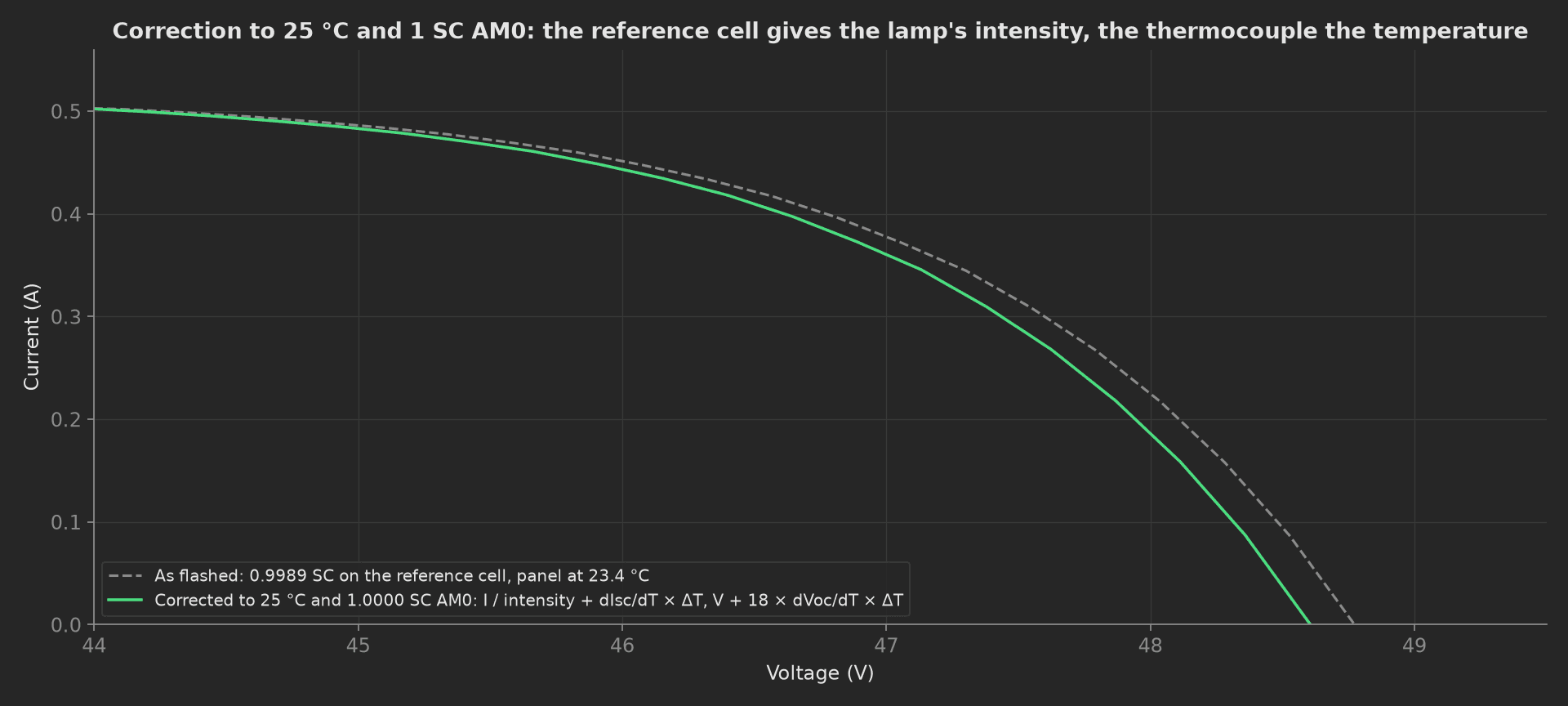
What the correction does on the mock's string 1: the panel was 1.6 K below 25 °C and the lamp 0.1 % under one solar constant, so the corrected curve moves 0.17 V left and 0.1 % up. Small on a healthy pulse at room temperature, and the reason a panel measured at 30 °C under a lamp at 0.96 SC reports the same power as one measured at 20 °C under 1.03 SC.
Bypass Diodes
Each bypass diode is made to carry the string current by reverse-biasing its cell group, and the drop across it is recorded. All 24 land in one measurement with the maximum and minimum limited: an open diode reads the reverse breakdown of the cells it was meant to protect, well above 1.2 V; a shorted one reads near zero:
import numpy as npfrom utils.recipe import CELL_ISC_A, DIODES_PER_STRING, STRINGSdef bypass_diodes(measurements, bench, log): """Every bypass diode carries the string current once, its forward drop recorded. An open diode reads the reverse breakdown of the shaded cells it was meant to protect; a shorted one reads zero.""" vf = [] for s in range(1, STRINGS + 1): for d in range(1, DIODES_PER_STRING + 1): vf.append(bench.bypass_diode_vf(s, d, CELL_ISC_A)) vf = np.array(vf) measurements.diodes.x_axis = list(range(1, len(vf) + 1)) measurements.diodes.y_axis.vf = vf.tolist() measurements.diodes.y_axis.vf.aggregations.max_v = float(vf.max()) measurements.diodes.y_axis.vf.aggregations.min_v = float(vf.min()) log.info(f"{len(vf)} bypass diodes: Vf {vf.min():.3f}..{vf.max():.3f} V at {CELL_ISC_A:.2f} A")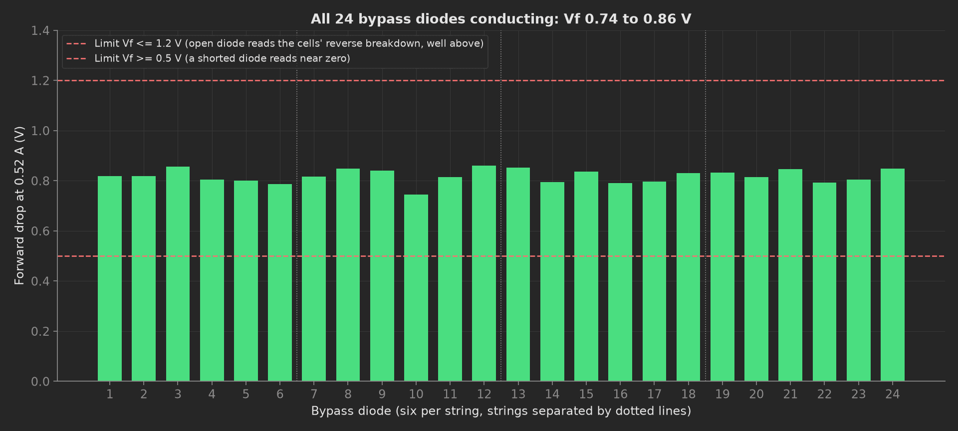
The mock panel's 24 diodes, all conducting between 0.74 and 0.86 V at 0.52 A.
Release
The teardown phase shorts the panel and logs the lamp pulses used, on the run and on the unit:
def release(measurements, bench, unit, log): """Teardown: panel shorted, lamp pulse count logged against the flash tube's rated life.""" bench.short_panel() measurements.pulses_this_run = bench.pulses_used() unit.metadata["flash_pulses"] = bench.pulses_used() log.info(f"Panel shorted, {bench.pulses_used()} pulses this run")Mock Plug
FlashBench stands in for the flasher, the reference cell, the IV load, the megohmmeter, the LCR meter and the thermocouples. It synthesizes four strings of 18 triple-junction cells (0.52 A, 2.70 V, 1.2 W each at 25 °C) with per-string gains within 0.5 % and string 3 at 98.5 %, a lamp delivering 1 SC ± 0.4 % per pulse, a panel at 23.4 °C, insulation at 2 GΩ, 118 nF of capacitance and 24 diodes at 0.82 V ± 0.03. The IV shape is a single-diode model with a fill factor near 0.87. Every method returns plain Python types because plug calls cross a JSON boundary; a measurement read back from measurements.<key> returns a proxy, so the phases keep locals for their log lines.
On a real bench, the class speaks to the flasher's controller for the pulse and to the IV load through its trigger, reads the reference cell's short-circuit current on every pulse, and drives the megohmmeter, the LCR meter and the thermocouple DAQ over SCPI. Use the reference cell's calibrated value from its certificate, keep the correction coefficients from the cell datasheet in the recipe, and record the reference cell's identity on every run. The phases, measurements and limits stay the same.