
Get the complete source, dependencies and setup instructions from the template repository.
Open the source on GitHubIntroduction
RC Link Overview
Every drone carries an RC link receiver (RX) that pairs with a hand-held transmitter (TX) and relays stick inputs to the flight controller at 50-1000 Hz. The link runs on 2.4 GHz or sub-GHz (868 / 915 MHz) ISM bands, and modulates with LoRa, FSK, or proprietary DSSS schemes depending on protocol. Common choices include ExpressLRS (open source, -112 dBm sensitivity at 150 Hz LoRa), TBS Crossfire, FrSky R9M, Spektrum DSMX, and DJI O3/O4.
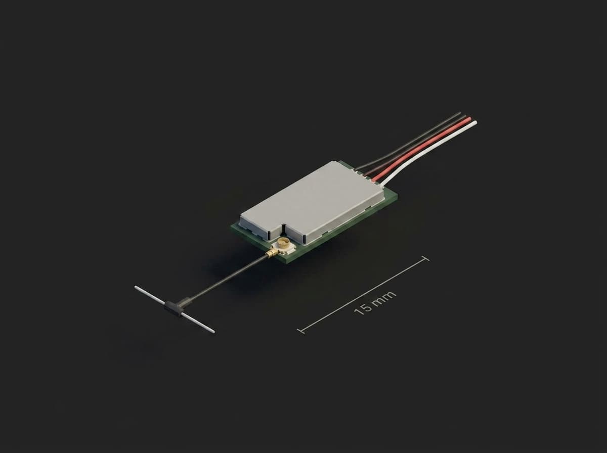
A nano receiver: the RF shield covers the LNA stage, the U.FL connector feeds the dipole, the whole board is about 15 mm long.
A weak or marginal RC link is a leading cause of drone loss. Failure modes include premature failsafe triggering (drone drops or initiates RTH mid-mission), inability to recover when link drops at altitude, and "fly-aways" where the receiver holds last stick values instead of cutting throttle. Per the Betaflight failsafe guide, the flight controller holds the last good channel values for 300 ms, then Stage 1 applies the configured channel fallback settings for the guard time (failsafe_delay, 1.5 s default in Betaflight 4.5) before Stage 2 engages, so a sub-spec receiver can silently misbehave through that window.
Test Purpose
Per-unit RC link verification measures the link's sensitivity, failsafe behavior, and timing response against a controlled signal-power sweep. Output fingerprint:
- RSSI vs attenuation curve: the receiver's reported RSSI (dBm) as the input power drops
- LQ (Link Quality) curve: packet success rate as power drops
- Failsafe threshold: the dBm at which the RX engages failsafe
- Sensitivity floor: the dBm at which the link breaks entirely
- Telemetry latency: round-trip time of telemetry packets
The sensitivity limit in this template (≤ -107 dBm at 250 Hz) sits just inside the official ExpressLRS sensitivity table (-108 dBm at 250 Hz), so a healthy receiver passes with margin and a degraded RF chain does not.
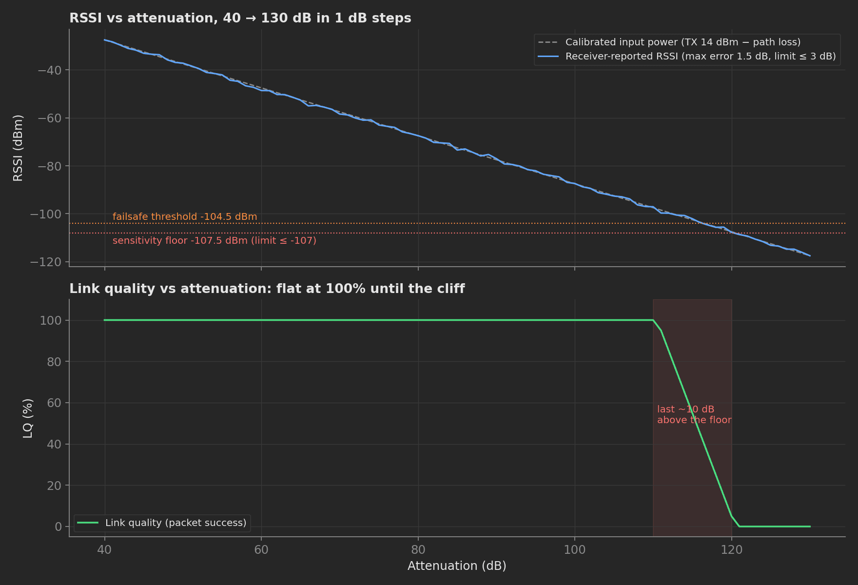
The sweep as the mock link produces it: reported RSSI stays within 1.5 dB of the calibrated input power, LQ holds 100% until the last 10 dB above the floor, and failsafe engages 4 dB before the link dies.
Per-unit testing catches defects invisible at incoming inspection: cracked antenna feedline (can cost tens of dB of sensitivity), U.FL connector misorientation (U.FL is rated for 30 mating cycles), dead LNA from VTX feedback, antenna fouled by carbon-fiber frame, wrong firmware version, and solder bridge on the matching network.
Beyond the RF content, this template demonstrates the framework's operator input components: the line operator picks the packet rate, TX power, and starting attenuation in the UI, the values are bound to measurements for traceability, and the same run executes unattended by pre-baking the answers with --ui-values.
Equipment & Setup
To implement RC link RSSI verification on a production line, the following are required:
- A shielded RF environment (Faraday tent or anechoic chamber) for the RX
- A programmable step attenuator in the RF path
- A reference TX running production firmware
- The Device Under Test (DUT): a drone (or RX module) with antenna installed
- A spectrum analyzer for diagnostic spot-checks
- A TofuPilot Framework procedure to step the attenuator, capture RX telemetry, and validate metrics
- The TofuPilot Dashboard to log results and trend supplier quality
Hardware Components
Shielded Environment
A compact fully anechoic OTA chamber (e.g. ETS-Lindgren) is the high-end choice for automated pattern and frequency sweeps. For production volume at lower capex, a Faraday tent (Select Fabricators or JRE Test) is the practical compromise; specify at least 70 dB isolation in the 2.4 GHz and 900 MHz bands. The TX sits outside, the RX inside, and the RF path runs through a bulkhead-mounted attenuator.
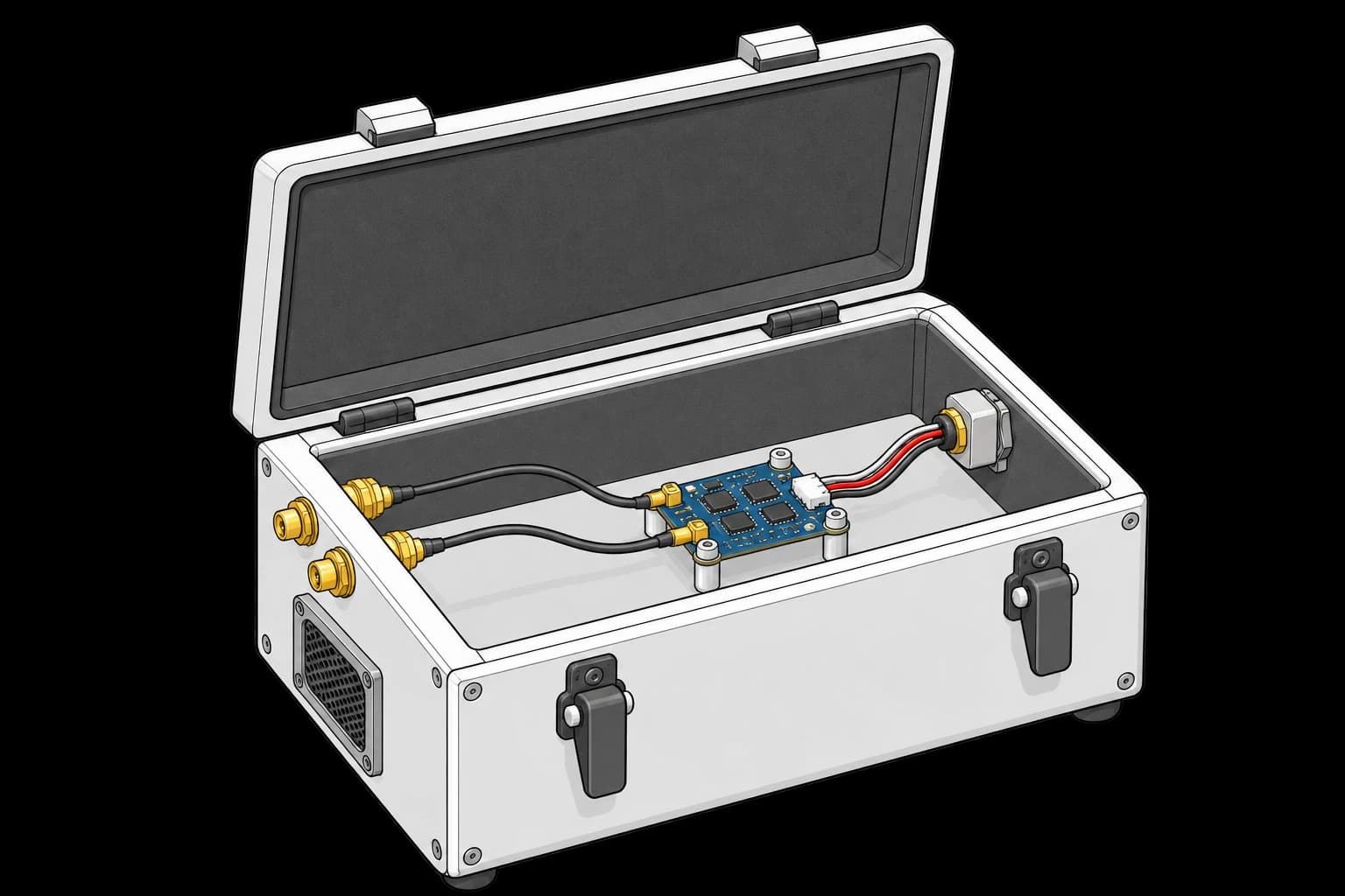
The receiver's coax leads connect through the enclosure wall separately from its electrical harness. The box is open for setup and closes during the RF sweep.
Programmable Attenuator
A JFW Industries 50P-2014 solid-state programmable step attenuator: 0-95 dB in 1 dB steps, 200-6000 MHz, USB or TTL controlled (the 50P-2013 is the 0-63 dB variant). A single attenuator covers both the 2.4 GHz and 900 MHz drone bands. Insertion accuracy ±0.5 dB up to 90 dB.
Spectrum Analyzer
For diagnostic spot-checks on RF chain defects, a Rigol DSA815-TG (9 kHz-1.5 GHz, tracking generator, preamp) covers 900 MHz at about $1,500. A Tektronix RSA306B USB real-time analyzer (9 kHz-6.2 GHz, about $3,500) covers 2.4 GHz. For go/no-go production-floor scans, an RF Explorer 6G Combo at under $500 suffices.
Reference TX
An ExpressLRS production line uses a golden TX module (Radiomaster TX16S running stock ELRS firmware) configured to the production-target packet rate. The TX is RF-shielded inside its own enclosure, with its antenna replaced by a low-loss U.FL → SMA pigtail routing into the attenuator. TX output power is locked at 25 mW (14 dBm) so the attenuation sweep maps cleanly to receiver-input dBm.
Custom Firmware
The RX runs production firmware with telemetry enabled. The test station captures telemetry over the flight controller's USB or a side-channel (the ExpressLRS Backpack forwards CRSF frames over ESP-NOW) and parses RSSI, LQ, packet rate, and round-trip latency. The ELRS Lua script sets the production packet rate and power on the TX.
Test Procedure
Overview
After mounting the DUT inside the Faraday tent and pairing TX/RX, the procedure runs:
- The operator confirms the link configuration (packet rate, TX power, starting attenuation) in the UI form.
- The configuration is applied to the telemetry link and the attenuator.
- Sweep attenuation across the link budget in 1 dB steps, logging RSSI and LQ per step, and find the sensitivity floor.
- Push attenuation past the floor to find the failsafe threshold and the failsafe margin, then measure telemetry round-trip latency.
- Validate every metric against its declared limits.
- Stream results to TofuPilot for traceability and analytics.
Total cycle ~90 s per DUT.
Why TofuPilot Framework?
TofuPilot Framework is a YAML + Python test framework built for hardware manufacturing. Instead of writing all your test logic, measurements, and limits inside Python code, you describe what the test does in a procedure.yaml file, and how in small Python phase files. The framework handles:
- Automatic Python environment management (via
uv) - Operator UI (no frontend code needed)
- Measurement validation and live charts
- Process isolation between phases and equipment plugs
Project Structure
The mock plugs model an ExpressLRS-grade link so the procedure runs green without hardware; swap them for JFW-USB and pyserial CRSF implementations on a real bench. Run it with tofupilot run . --no-tui --no-kiosk --json --ui-values ui.json, or drop --ui-values to answer the operator prompts interactively. You can find the full source on GitHub.
The Procedure File
This is the exact file the template ships, verified end to end with the CLI:
procedure.yaml139 lines
name: RC Link RSSI vs Range Verificationversion: 0.1.0description: Sweeps a calibrated attenuator across the RC link budget and verifies RSSI accuracy, LQ, failsafe threshold, and telemetry latency.unit: auto_identify: true serial_number: description: "Receiver serial from the label under the antenna" placeholder: "RX-000000" pattern: "^RX-\\d{6}$" default_value: "RX-004217" part_number: default_value: "ELRS-RX-24G"plugs: - name: Step Attenuator description: Mock JFW 50P-2014 programmable step attenuator, 0-95 dB in 1 dB steps. python: plugs.attenuator:StepAttenuator key: attenuator config: insertion_loss_db: 1.5 - name: Link Telemetry description: Mock CRSF telemetry stream from the flight controller. python: plugs.telemetry:LinkTelemetry key: telemetrymain: - name: Configure Link key: configure_link ui: components: - key: packet_rate type: select label: "Packet Rate" bind: measurements.packet_rate_hz options: - label: "50 Hz" value: "50" - label: "150 Hz" value: "150" - label: "250 Hz" value: "250" - label: "500 Hz" value: "500" default_value: "250" - key: tx_power_dbm type: number_input label: "TX Power (dBm)" default_value: 14 bind: measurements.tx_power_dbm - key: start_attenuation_db type: slider label: "Start Attenuation (dB)" min: 0 max: 40 default_value: 0 bind: measurements.start_attenuation_db measurements: - name: Packet Rate key: packet_rate_hz unit: Hz validators: - operator: in expected_value: ["50", "150", "250", "500"] - name: TX Power key: tx_power_dbm unit: dBm - name: Start Attenuation key: start_attenuation_db unit: dB - name: Apply Link Config key: apply_config python: phases.apply_config depends_on: [configure_link] measurements: - name: RF Channel key: rf_channel description: Active regulatory channel index; 0 and 13 are reserved on this SKU. validators: - operator: not in expected_value: [0, 13] - name: RSSI Sweep key: rssi_sweep python: phases.rssi_sweep depends_on: [apply_config] measurements: - name: RSSI And LQ vs Attenuation key: rssi_lq_sweep title: RSSI and LQ vs Attenuation description: Receiver-reported RSSI and link quality against the calibrated attenuation sweep. x_axis: legend: Attenuation unit: dB y_axis: - legend: RSSI key: rssi unit: dBm aggregations: - type: rssi_error_max unit: dB validators: - operator: "<=" expected_value: 3.0 - legend: Link Quality key: lq unit: "%" - name: Sensitivity Floor key: sensitivity_floor_dbm unit: dBm validators: - operator: "<=" expected_value: -107.0 - name: Failsafe And Latency key: failsafe_latency python: phases.failsafe_latency depends_on: [rssi_sweep] measurements: - name: Failsafe Threshold key: failsafe_threshold_dbm unit: dBm validators: - operator: ">=" expected_value: -110.0 - name: Failsafe Margin key: failsafe_margin_db unit: dB description: Gap between failsafe engagement and total link loss; must engage before the link breaks. validators: - operator: ">=" expected_value: 3.0 - name: Telemetry Round Trip key: telemetry_rtt_ms unit: ms validators: - operator: "<=" expected_value: 50.0Framework features to notice:
- Operator input, bound to measurements: the
Configure Linkphase is pure UI, no Python. Theselect,number_input, andslidercomponents each carry abind: measurements.*, so the operator's choices land as validated measurements on the run (the packet rate must be one of the four production rates via aninvalidator). Select options use the{label, value}form. Because select values are strings, the packet rate is recorded as a string measurement (withunit: Hzfor display) and the consuming phase casts it withint(). - Unit field validation: the serial number field declares a
pattern,placeholder, anddescription; operator input that does not match^RX-\d{6}$is rejected before the run starts. not invalidator: the RF channel measurement rejects the two reserved channel indices with a one-line validator.- Plug
config: the attenuator's calibrated insertion loss lives in YAML, not in code, and arrives as an__init__keyword argument. - Custom aggregation:
rssi_error_maxis a free-named aggregation on the RSSI axis; Python computes it, the YAML validator enforces the ±3 dB reporting-accuracy budget.
Reading Operator Input
The ui object injected into Python phases is write-only (it updates display components). Operator input travels through bind: into measurements, and the next phase reads them through previous-results injection: naming a parameter after a completed phase's key injects a read-only result object.
def apply_config(measurements, configure_link, telemetry, attenuator, log): packet_rate = int(configure_link.packet_rate_hz) tx_power = float(configure_link.tx_power_dbm) start_attenuation = int(configure_link.start_attenuation_db) telemetry.configure(packet_rate) attenuator.set_db(start_attenuation) log.info(f"Link at {packet_rate} Hz, TX {tx_power} dBm, start att {start_attenuation} dB") measurements.rf_channel = telemetry.rf_channel()For unattended runs the answers come from a JSON file keyed by phase and component:
{ "configure_link": { "packet_rate": "250", "tx_power_dbm": 14, "start_attenuation_db": 0 }}tofupilot run . --ui-values ui.json injects these as if the operator had typed them; the binds still fire, so the measurements and their validators behave identically in attended and unattended runs.
RSSI Sweep
The sweep starts at 40 dB attenuation (about -28 dBm at the receiver after the 1.5 dB insertion loss, the top of the linear reporting range) and steps 1 dB at a time down past the floor. At each step the receiver reports RSSI and LQ; while the link is alive, the absolute error between reported RSSI and the calibrated input power feeds the accuracy aggregation.
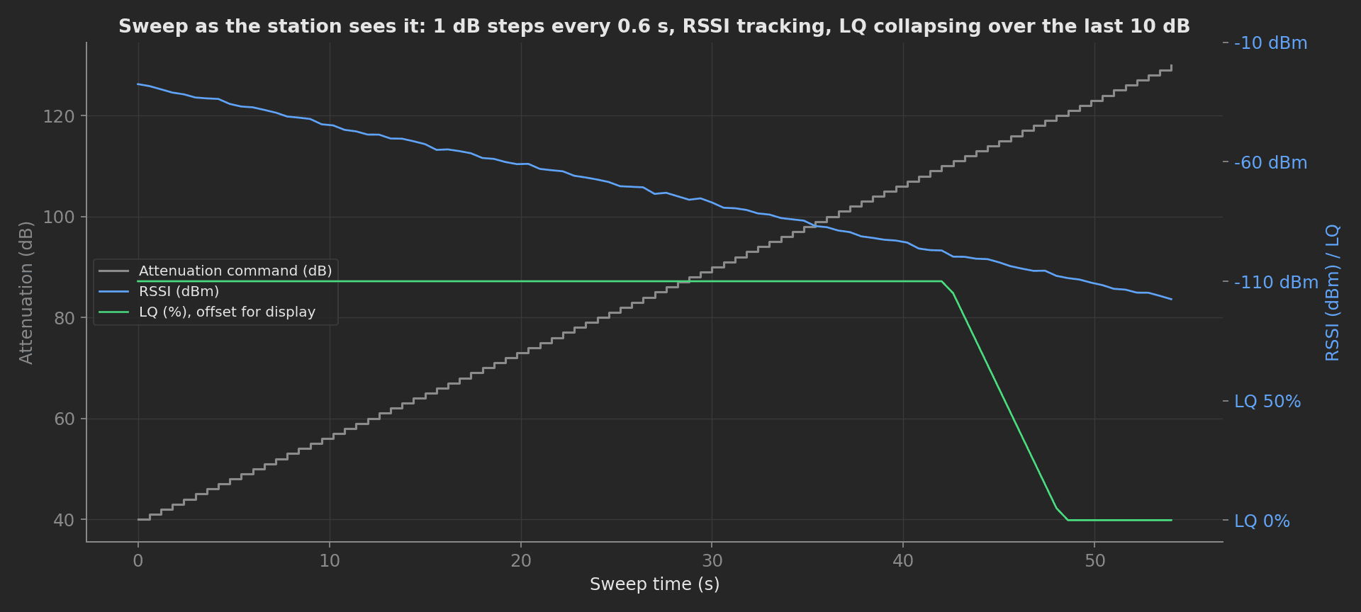
The sweep as the station sees it: 91 attenuation steps, RSSI following the staircase down, LQ collapsing only in the last 10 dB before the floor.
phases/rssi_sweep.py33 lines
from utils.link_budget import input_power_dbmTX_POWER_DBM = 14.0 # golden TX locked at 25 mWdef rssi_sweep(measurements, attenuator, telemetry, log): attenuations = [] rssis = [] lqs = [] rssi_errors = [] floor = None for att in range(40, 131, 1): attenuator.set_db(att) power = input_power_dbm(TX_POWER_DBM, attenuator.path_loss_db()) rssi = telemetry.rssi_at(power) lq = telemetry.lq_at(power) attenuations.append(att) rssis.append(rssi) lqs.append(lq) if telemetry.link_alive_at(power): rssi_errors.append(abs(rssi - power)) floor = power measurements.rssi_lq_sweep.x_axis = attenuations measurements.rssi_lq_sweep.y_axis.rssi = rssis measurements.rssi_lq_sweep.y_axis.lq = lqs measurements.rssi_lq_sweep.y_axis.rssi.aggregations.rssi_error_max = max(rssi_errors) log.info(f"Sensitivity floor: {floor:.1f} dBm") measurements.sensitivity_floor_dbm = floorFailsafe Threshold and Latency
The flight controller publishes a failsafe-active flag over CRSF. The phase records the power at which failsafe engages and the power at which the link dies; the failsafe margin between them must be at least 3 dB, otherwise the link cuts off before failsafe engages and the drone enters a "no command" hold state.
phases/failsafe_latency.py24 lines
from utils.link_budget import input_power_dbmTX_POWER_DBM = 14.0def failsafe_latency(measurements, attenuator, telemetry, log): failsafe_at = None link_lost_at = None for att in range(100, 141, 1): attenuator.set_db(att) power = input_power_dbm(TX_POWER_DBM, attenuator.path_loss_db()) if failsafe_at is None and telemetry.failsafe_active_at(power): failsafe_at = power if not telemetry.link_alive_at(power): link_lost_at = power break log.info(f"Failsafe at {failsafe_at:.1f} dBm, link lost at {link_lost_at:.1f} dBm") measurements.failsafe_threshold_dbm = failsafe_at measurements.failsafe_margin_db = failsafe_at - link_lost_at rtts = [telemetry.telemetry_rtt_ms() for _ in range(50)] measurements.telemetry_rtt_ms = sum(rtts) / len(rtts)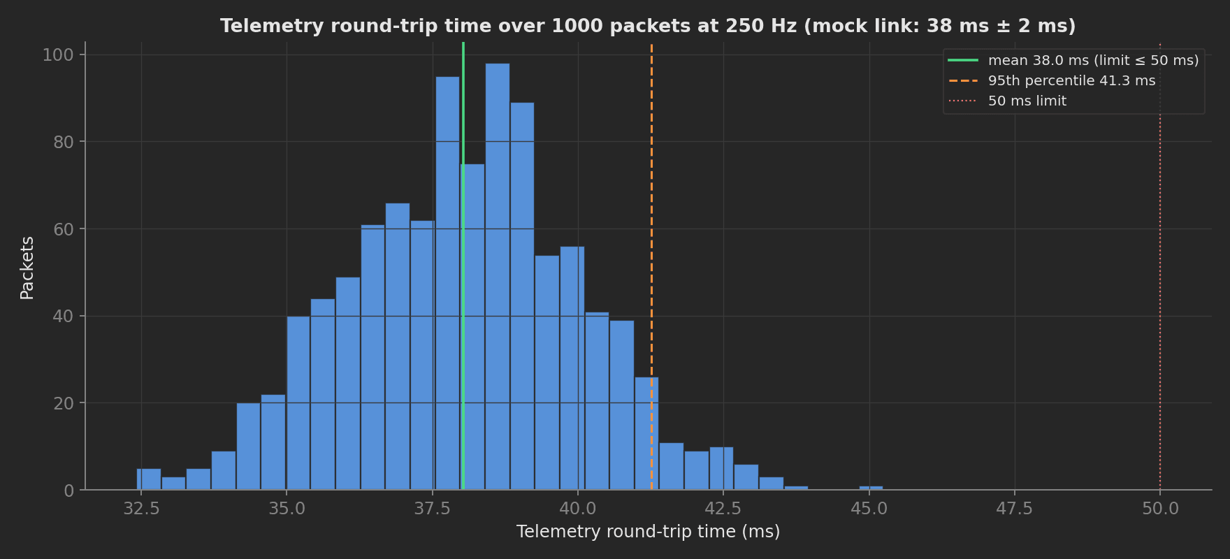
Round-trip time distribution of the mock link at 250 Hz: 38 ms mean with 2 ms spread, well inside the 50 ms limit. A real link with a congested telemetry path shows a long tail here before the mean moves.
Mock Plugs
The attenuator mock shows the plug config pattern; the calibrated insertion loss is a YAML value that arrives as a constructor argument:
class StepAttenuator: def __init__(self, insertion_loss_db): self.insertion_loss_db = float(insertion_loss_db) self._db = 0 print(f"Attenuator ready, insertion loss {self.insertion_loss_db} dB") def set_db(self, db): self._db = int(db) def current_db(self): return self._db def path_loss_db(self): return self._db + self.insertion_loss_dbThe telemetry mock models an ExpressLRS-grade receiver (floor -108 dBm, failsafe -104 dBm, RTT keyed to the configured packet rate) so every limit in the YAML exercises realistically without hardware.