
Get the complete source, dependencies and setup instructions from the template repository.
Open the source on GitHubIntroduction
Daisy-Chain Overview
A pack of 400 V is monitored by a chain of cell-monitoring modules, each floating at its own stack potential, each talking to the next over one isolated twisted pair. TI's BQ79616 family runs a bidirectional, half-duplex differential link at 2 MHz through 2.2 nF isolation capacitors or a pulse transformer, reclocked at every device; ADI's isoSPI does the same at 1 Mbps through a transformer with the drive current and the receive threshold both set by one resistor divider. Both links have a property that makes them the classic escape of a BMS production line: the defects that matter are analog margin defects, and they pass a protocol test on a 20 cm fixture jumper and fail on the pack harness.
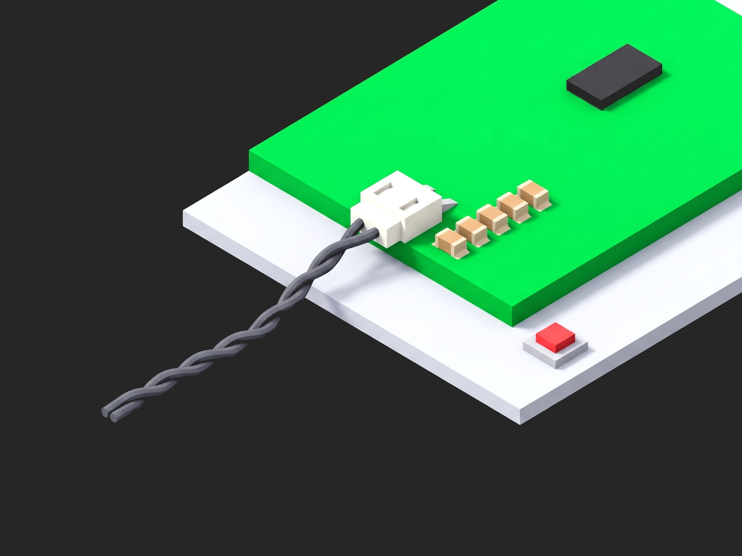
The daisy-chain port of one module: the two-pin connector, the twisted pair, and the four series isolation capacitors that set how much of the 2 MHz pulse reaches the next module.
The numbers to build the test on are in TI SLVAEP4, the daisy-chain application note: data pulses of 250 ns ± 20 ns, tones of 1 µs ± 8 %, a good waveform above 1.8 V differential, and a bit that is not detected at all when its starting amplitude is below 1.6 V, whatever its ending amplitude. A wrong isolation capacitor (1 nF where 2.2 nF belongs), a missing common-mode choke, a transformer from a different reel on one side of the link, or on isoSPI a wrong IBIAS/ICMP divider that raises the threshold while leaving the drive alone: each one leaves the bench amplitude comfortably above 1.8 V and the pack amplitude below 1.6 V. A test that asks "did it communicate?" over a jumper answers yes to all of them.
Test Purpose
The procedure records one link fingerprint per module:
- The four series isolation capacitors, measured on an LCR meter before the module is powered
- Wake and auto-address over the jumper, the reclock delay and the idle common-mode voltage
- Pulse amplitude (start and end of the worst double-bit) and pulse timing (data and tone) on the 20 cm jumper and again on a 3 m worst-case harness
- Frame loss over 1000 broadcast reads on the long harness at -15, 0 and +15 V of common-mode offset
- The fault summary before and after the stress
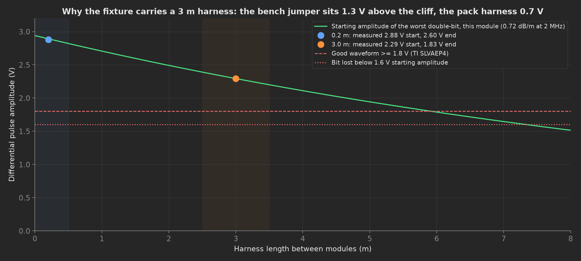
The mock module on its attenuation curve: 2.9 V on the jumper, 2.3 V on the 3 m harness, the cliff at 7.5 m. A module with a 1 nF capacitor sits on a curve half as high, and its jumper reading would still clear 1.8 V.
The framework mechanics on show are a component check in setup: before the DUT is powered, the same measurement recorded on two fixtures with the limit where it matters, limits copied from the application note, a multi-dimensional measurement with an integer aggregation validated == 0, JSON == on the fault summary before and after stress, and a teardown: that restores the fixture.
Equipment & Setup
To run this test on a production line, the following are required:
- A host bridge for the chain (a BQ79600 on a UART adapter, or an LTC6820 for isoSPI)
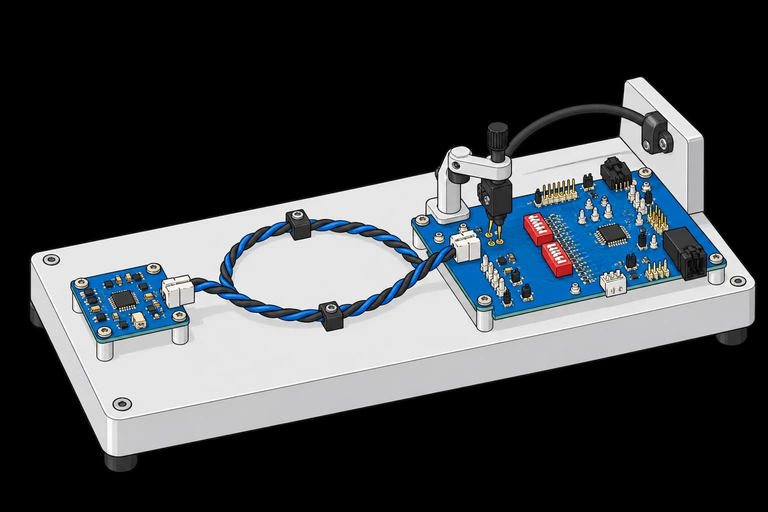
- A relay-switched harness: a 20 cm jumper and a real 3 m twisted pair in the fixture
- A differential probe and a digitiser at 1 GS/s or better on the module's COM pins
- An isolated DC source in series with the harness return, for the common-mode offset
- An LCR meter behind the probe head for the isolation capacitors
- The Device Under Test (DUT): one cell-monitoring module with its production firmware
- A TofuPilot Framework procedure to switch the fixtures, capture the margins and validate the limits
- The TofuPilot Dashboard to trend the harness amplitude across modules, which is where a capacitor reel change shows first
Hardware Components
Bridge, Harness and Probe
The BQ79600-Q1 bridges a UART or SPI host to the daisy chain and supports mixed isolation on the two sides. The harness relays are the fixture's own; the 3 m pair is the worst case of the pack's inter-module runs, with the isolation network of the neighbouring module at its far end. Any differential probe with 1 GHz of bandwidth on a Keysight or Tektronix scope resolves a 250 ns pulse and its 20 ns window; the capture is a single-shot on the COMH pair during a broadcast read.
A host bridge connects to the cell-monitoring board through a twisted-pair harness. A supported probe contacts the communication test pads; switching and measurement instruments are external.
Isolation Network
Capacitor isolation is the low-cost option: 2.2 nF rated at twice the working voltage, up to 5.6 nF; a common-mode choke (TDK ACT45B-510 or -101, Würth 744242471) is added for longer runs or noisier packs; a pulse transformer is the robust option, with the same part number on both sides of every link. The setup phase measures the four series capacitors on an LCR meter at 1 kHz through the probe head, before the chain is powered, because a wrong value is a component defect and a component check finds it in milliseconds; the margin phases then confirm what the capacitor did to the pulse.
Common-Mode Source
The receiver is designed to survive ±20 V of common mode between modules (inverter noise, bulk current injection); above that the ESD structures clamp. An isolated supply in series with the harness return applies ±15 V during the frame-loss count. A missing choke or a marginal capacitor shows as loss at ±15 V before it shows at 0 V.
Where the Limits Come From
No standard specifies a daisy-chain production test; ISO 11898 and its conformance plans cover CAN, not this link, and ISO 26262 asks that the safety-related communication be controlled in production without naming a voltage. The limits are the application note's:
| Test | Limit | Basis |
|---|---|---|
| Isolation capacitors | 1.8 to 2.6 nF | 2.2 nF ± 10 % plus the meter |
| Data pulse width | 230 to 270 ns | 250 ns ± 20 ns |
| Tone pulse width | 0.92 to 1.08 µs | 1 µs ± 8 % |
| Pulse starting amplitude | ≥ 1.8 V, on the harness | good waveform; the bit is lost below 1.6 V |
| Idle common mode | 2.21 to 2.76 V | V(DCCM) |
| Reclock delay | ≤ 5 µs | 4 µs typical, 5 µs maximum per device |
| Frame loss at ±15 V | 0 of 1000 | ±20 V survival |
The amplitude limit is applied on the harness and only recorded on the jumper: every module passes on the jumper, so a limit there catches nothing. The 3 m figure is this pack's worst inter-module run; the fixture carries the real length, not a calculation.
Test Procedure
Overview
The procedure maps the test onto the framework's three stages. The capacitor check lives in setup: so the chain is never powered on a module with a wrong isolation network. Restoring the jumper and the common mode lives in teardown: so the next module starts from a known fixture.
- Setup: four isolation capacitors on the LCR meter.
- Main: wake, auto-address, reclock delay, idle common mode, fault summary, on the jumper.
- Main: pulse amplitude and timing on the jumper, then on the 3 m harness.
- Main: frame loss at -15, 0 and +15 V on the harness, fault summary after.
- Teardown: jumper back, common mode off.
Every metric validates against limits declared in procedure.yaml, and results stream to TofuPilot for trending.
Why TofuPilot Framework?
TofuPilot Framework is a YAML + Python test framework built for hardware manufacturing. Instead of writing all your test logic, measurements, and limits inside Python code, you describe what the test does in a procedure.yaml file, and how in small Python phase files. The framework handles:
- Automatic Python environment management (via
uv) - Operator UI (no frontend code needed)
- Measurement validation and live charts
- Process isolation between phases and equipment plugs
Project Structure
You can find the full source on GitHub. The ChainBench plug is a mock of the bridge, the harness relays, the probe, the common-mode source and the LCR meter together, synthesizing a healthy module with an attenuation of 0.72 dB/m at 2 MHz, so the procedure runs end-to-end without a bench or a module connected.
tofupilot run .For CI or bench automation, the same run executes headless:
tofupilot run . --no-tui --no-kiosk --jsonThe Procedure File
procedure.yaml declares the unit, the bench plug, and the three stages with every measurement and limit:
procedure.yaml163 lines
name: BMS Daisy-Chain Signal Integrityversion: 0.1.0description: Daisy-chain communication integrity of a cell-monitoring module. Isolation capacitors measured before power, wake and auto-address with reclock delay, differential pulse amplitude and timing on a 20 cm jumper and on a 3 m worst-case harness, frame loss at three common-mode offsets.unit: auto_identify: true serial_number: description: "Scan the module's data-matrix" placeholder: "CMU-000000" pattern: "^CMU-\\d{6}$" default_value: "CMU-031742" part_number: default_value: "PCB-CMU-16S-R2" batch_number: default_value: "LOT-2026-37"plugs: - name: Chain Bench description: "Host bridge, switchable harness, differential probe and digitiser, common-mode source, LCR meter (mock, one plug per bench)" python: plugs.chain_bench:ChainBench key: benchsetup: - name: Isolation Caps key: isolation_caps python: phases.isolation_caps measurements: - name: Cap COMH P key: cap_comh_p_nf unit: nF validators: - {operator: ">=", expected_value: 1.8} - {operator: "<=", expected_value: 2.6} - name: Cap COMH N key: cap_comh_n_nf unit: nF validators: - {operator: ">=", expected_value: 1.8} - {operator: "<=", expected_value: 2.6} - name: Cap COML P key: cap_coml_p_nf unit: nF validators: - {operator: ">=", expected_value: 1.8} - {operator: "<=", expected_value: 2.6} - name: Cap COML N key: cap_coml_n_nf unit: nF validators: - {operator: ">=", expected_value: 1.8} - {operator: "<=", expected_value: 2.6}main: - name: Wake Address key: wake_address python: phases.wake_address measurements: - name: Address key: address validators: - {operator: "==", expected_value: 1} - name: Reclock Delay key: reclock_us unit: µs description: Per-device reclock, 4 us typical, 5 us maximum; a slow reclock on one module adds up over a 24-device stack. validators: - {operator: "<=", expected_value: 5.0} - name: Idle Common Mode key: idle_common_mode_v unit: V description: V(DCCM) 2.21 to 2.76 V; the COM pins rest at 2.5 V between packets. validators: - {operator: ">=", expected_value: 2.21} - {operator: "<=", expected_value: 2.76} - name: Faults key: faults validators: - operator: "==" expected_value: comm: false otp: false sys: false - name: Pulse Margin key: pulse_margin python: phases.pulse_margin depends_on: [wake_address] measurements: - name: Jumper Start Amplitude key: jumper_start_v unit: V validators: - {operator: ">=", expected_value: 1.8} - name: Jumper End Amplitude key: jumper_end_v unit: V - name: Jumper Data Width key: jumper_data_width_ns unit: ns validators: - {operator: ">=", expected_value: 230.0} - {operator: "<=", expected_value: 270.0} - name: Jumper Tone Width key: jumper_tone_width_us unit: µs validators: - {operator: ">=", expected_value: 0.92} - {operator: "<=", expected_value: 1.08} - name: Harness Start Amplitude key: harness_start_v unit: V description: "On the 3 m worst-case harness. Good above 1.8 V; the receiver drops the bit below 1.6 V starting amplitude. This is the number the jumper cannot give you." validators: - {operator: ">=", expected_value: 1.8} - name: Harness End Amplitude key: harness_end_v unit: V description: Ending amplitude of the worst double-bit; recorded for trending, the start amplitude carries the limit. - name: Harness Data Width key: harness_data_width_ns unit: ns validators: - {operator: ">=", expected_value: 230.0} - {operator: "<=", expected_value: 270.0} - name: Harness Tone Width key: harness_tone_width_us unit: µs validators: - {operator: ">=", expected_value: 0.92} - {operator: "<=", expected_value: 1.08} - name: Common Mode Sweep key: common_mode_sweep python: phases.common_mode_sweep depends_on: [pulse_margin] timeout: 2m measurements: - name: Frame Loss key: frame_loss title: Frames lost of 1000 on the 3 m harness at each common-mode offset x_axis: legend: Common mode unit: V y_axis: - legend: Lost frames key: lost aggregations: - type: total validators: - {operator: "==", expected_value: 0} - name: Faults After Sweep key: faults_after_sweep validators: - operator: "==" expected_value: comm: false otp: false sys: falseteardown: - name: Release key: release python: phases.releaseFramework features to notice:
- A component check before power. The setup phase measures four capacitors with the DUT unpowered; a wrong reel fails here with the value, not three phases later with a lost bit.
- Two fixtures, one limit.
jumper_start_vandharness_start_vare the same capture on two harnesses; the limit lives on the harness one and the jumper one is recorded for the trend. - Integer aggregation
== 0. The frame-loss curve carries atotalaggregation validated as an exact zero. - Fault summary before and after.
faultsandfaults_after_sweepcompare the same object twice; a communication fault raised by the stress is caught even when every frame came back. teardown:restores the fixture. Jumper back and common mode off whatever the outcome.
Isolation Caps
The setup phase reads the four series capacitors through the probe head with the module unpowered and records the isolation type on the unit metadata:
from utils.recipe import ISOLATION_CAP_NFdef isolation_caps(measurements, bench, unit, log): """Setup: the four series isolation capacitors measured on the LCR meter through the probe head before the chain is powered. A 1 nF part where 2.2 nF belongs passes every protocol test on the jumper and fails at pack length; it is a component check, not a comms check.""" caps = {pin: bench.isolation_cap_nf(pin) for pin in ("comh_p", "comh_n", "coml_p", "coml_n")} measurements.cap_comh_p_nf = caps["comh_p"] measurements.cap_comh_n_nf = caps["comh_n"] measurements.cap_coml_p_nf = caps["coml_p"] measurements.cap_coml_n_nf = caps["coml_n"] unit.metadata["isolation"] = "capacitive 2.2 nF" log.info(f"Module {unit.serial_number}: isolation caps {caps} nF")Wake Address
The bridge wakes the chain with the tone, auto-addresses, and the phase reads back the address the module took, the reclock delay, the idle common-mode voltage on the COM pins and the fault summary. This is the protocol-level test every station already does; here it is the gate for the margin phases, not the verdict:
from utils.recipe import JUMPER_Mdef wake_address(measurements, bench, log): """Wake the chain over the jumper, auto-address, read the reclock delay and the fault summary. The protocol-level test, and the one every station already does.""" bench.set_harness(JUMPER_M) bench.set_common_mode_v(0.0) res = bench.wake_and_autoaddress() measurements.address = res["address"] measurements.reclock_us = res["reclock_us"] measurements.idle_common_mode_v = bench.idle_common_mode_v() measurements.faults = bench.fault_summary() log.info(f"Address {res['address']}, reclock {res['reclock_us']:.2f} us, idle common mode {measurements.idle_common_mode_v} V")Pulse Margin
The same single-shot capture on both harnesses: the differential probe on COMH during a broadcast read, the worst double-bit found (two adjacent pulses of opposite polarity, the second starting from where the first drooped), its starting and ending amplitude and its width, plus the width of a tone. The harness values carry the amplitude limit:
phases/pulse_margin.py19 lines
from utils.recipe import JUMPER_M, WORST_CASE_HARNESS_Mdef pulse_margin(measurements, bench, log): """Differential pulse amplitude and timing on the jumper and on the worst-case harness. The amplitude on the long harness is the number that predicts field failures: below 1.6 V starting amplitude the receiver drops the bit, whatever the protocol test on the bench said.""" for metres, key in ((JUMPER_M, "jumper"), (WORST_CASE_HARNESS_M, "harness")): bench.set_harness(metres) bench.wake_and_autoaddress() pulse = bench.capture_data_pulse() tone = bench.capture_tone() setattr(measurements, f"{key}_start_v", pulse["start_v"]) setattr(measurements, f"{key}_end_v", pulse["end_v"]) setattr(measurements, f"{key}_data_width_ns", pulse["width_ns"]) setattr(measurements, f"{key}_tone_width_us", tone["width_us"]) log.info(f"{metres:.1f} m: pulse {pulse['start_v']:.2f} -> {pulse['end_v']:.2f} V, data {pulse['width_ns']:.0f} ns, tone {tone['width_us']:.3f} us") bench.set_harness(JUMPER_M)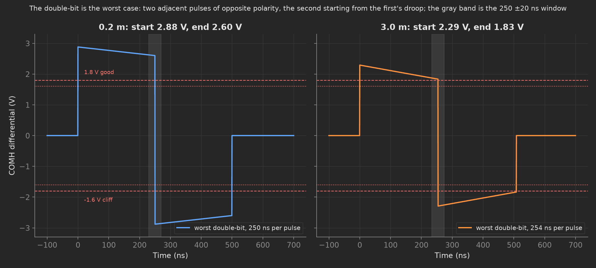
The double-bit on both fixtures. On the harness the second pulse starts at 1.83 V, above the 1.8 V line by 30 mV; that margin is what the trend across a batch watches, and it is invisible on the jumper.
Common Mode Sweep
On the 3 m harness, 1000 broadcast reads at -15 V, 0 V and +15 V of common-mode offset between the module and the bridge, the frames that came back without a valid CRC counted at each step:
phases/common_mode_sweep.py23 lines
from utils.recipe import COMMON_MODE_STEPS_V, FRAMES, WORST_CASE_HARNESS_Mdef common_mode_sweep(measurements, bench, log): """Frame loss over 1000 broadcast reads on the worst-case harness at three common-mode offsets. The receiver is specified to survive +-20 V of common mode; a missing choke or a wrong cap shows as loss at +-15 V before it shows at 0 V.""" bench.set_harness(WORST_CASE_HARNESS_M) bench.wake_and_autoaddress() losses = [] for cm in COMMON_MODE_STEPS_V: bench.set_common_mode_v(cm) lost = bench.frame_loss(FRAMES) losses.append(lost) log.info(f"Common mode {cm:+.0f} V: {lost} of {FRAMES} frames lost") bench.set_common_mode_v(0.0) bench.set_harness(0.2) measurements.frame_loss.x_axis = COMMON_MODE_STEPS_V measurements.frame_loss.y_axis.lost = losses measurements.frame_loss.y_axis.lost.aggregations.total = int(sum(losses)) measurements.faults_after_sweep = bench.fault_summary()Mock Plug
ChainBench stands in for five instruments because the pulse the probe sees depends on the harness the relays selected and the common mode the source applied. It synthesizes four capacitors between 2.18 and 2.26 nF, a 2.94 V drive attenuated at 0.72 dB/m, a double-bit droop of 0.28 V plus 0.06 V per metre, data pulses of 251 ns plus 1.8 ns per metre, tones of 1.003 µs, a 4.1 µs reclock, and zero frame loss while the amplitude margin over the 1.6 V cliff exceeds 0.3 V and the common mode stays inside ±20 V. Every method returns plain Python types because plug calls cross a JSON boundary; a measurement read back from measurements.<key> returns a proxy, so the phases keep locals for their log lines.
On a real bench, the class speaks the bridge's protocol over pyserial, drives the harness relays and the common-mode source, and pulls the single-shot capture from the scope over SCPI (:MEAS:VAMP, :MEAS:PWID on the differential channel). For an isoSPI link the same phases apply with the LTC6820's ~150 ns CS pulses and ~50 ns data pulses, and the divider on IBIAS/ICMP becomes the component checked in setup. Keep the worst-case harness in the fixture; it is the cheapest countermeasure to the whole defect class. The phases, measurements and limits stay the same.