
Get the complete source, dependencies and setup instructions from the template repository.
Open the source on GitHubIntroduction
Weld Resistance Overview
A battery module is a few hundred laser welds in series and parallel. Each cell-to-busbar joint carries the pack current, and each one that came out of the laser with insufficient penetration, a crack, porosity or a contaminated interface has a higher resistance than its neighbours. At 100 A that difference is heat, and the joint with the highest resistance is the hottest point of the module for the rest of its life; the defect population that becomes a thermal event in the field starts here. A production module has more than forty thousand of these joints per pack on a large EV platform, so the inspection has to be automated, fast, and precise enough to separate a good weld from a marginal one at a few tens of micro-ohms.
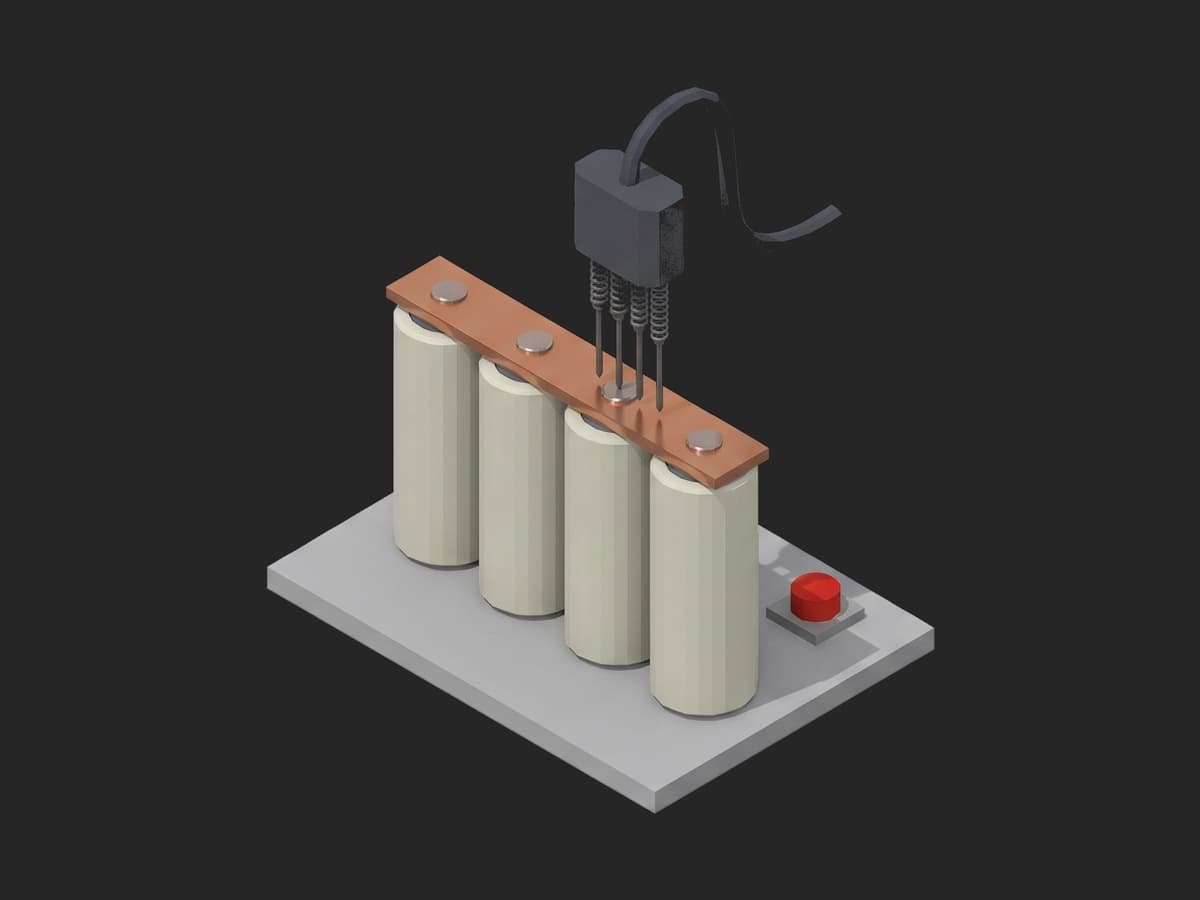
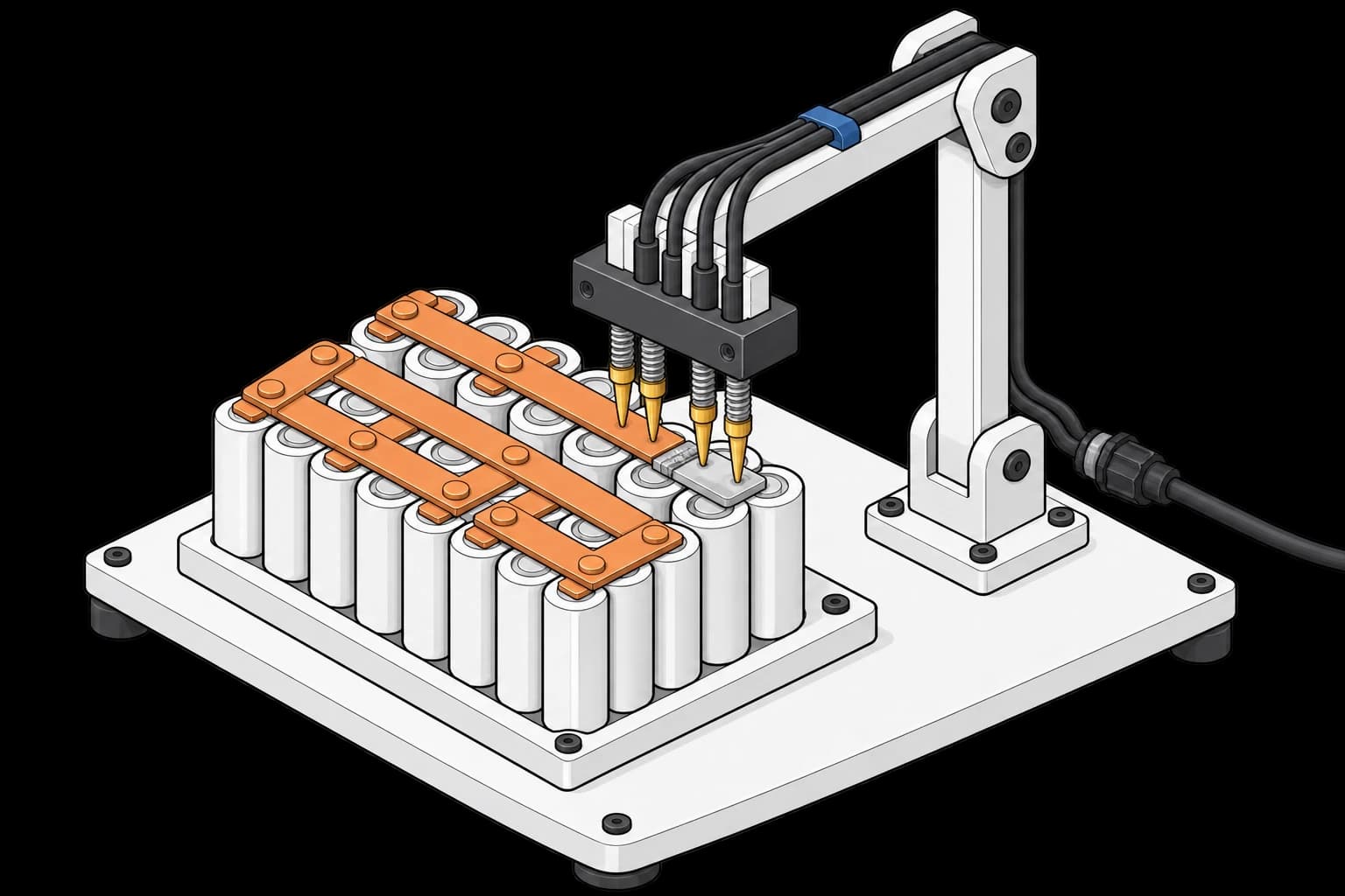
One busbar of the module: four cells, four laser weld spots, and the four-wire probe head on one of them. Two probes force the current through the joint, two read the drop.
The numbers are small. Hioki measured a real spot weld at 86.1 µΩ, repeatable to 85.7 to 86.2 µΩ once the temperature was corrected (see Hioki's weld resistance application note). A good joint and a shallow one differ by tens of micro-ohms; a two-wire measurement is off by the probe and cable resistance, a thousand times the signal. Two more effects of the same order sit on top: the joint is still cooling when it is read (copper drifts 0.393 % per kelvin, so a joint at 40 °C reads 8 % high), and a copper-to-aluminium joint is a thermocouple whose EMF adds to the voltage drop the meter reads. The measurement is four-wire, temperature-corrected, and taken with a bipolar test current that cancels the thermoelectric voltage, or it is not a measurement.
Test Purpose
The procedure records one interconnect fingerprint per module:
- Probe path resistance and the contact of the reference probe pair, before any weld is read
- All 48 cell-to-busbar welds: raw resistance, joint temperature and the value corrected to 20 °C, with the maximum, the median and the spread validated
- The correction itself, verified on an unwelded reference section of the busbar read at the same moment
- The 11 busbar links of the series string and their sum, the module's interconnect resistance for the pack model
- An optional OVC verification of how much the thermoelectric EMF would have shifted the readings
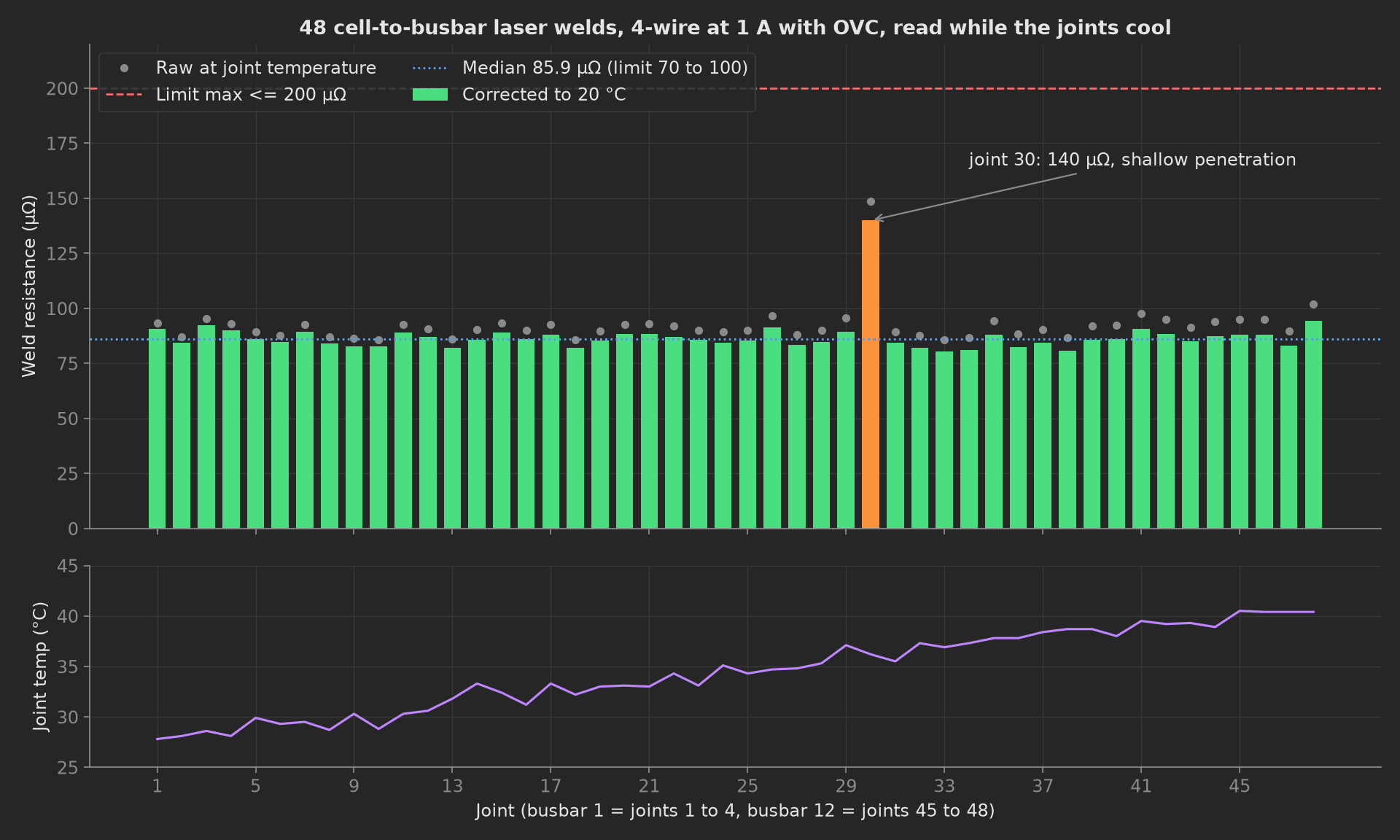
The mock module 10 to 25 s out of the laser: raw readings run 3 to 8 % above the corrected bars because the joints are still 8 to 20 K above 20 °C, the gradient along the module follows the weld sequence, and joint 30 sits at 1.6 times the median with shallow penetration, under the absolute limit but exactly what the spread limit and the trend across a batch exist to catch.
The framework mechanics on show are a multi-dimensional measurement with three curves and aggregations validated on one of them, an absolute and a relative limit on the same data, a measurement that validates the correction rather than the part, a disabled phase for a periodic check, setup and teardown stages, and a sequential depends_on chain on one meter.
Equipment & Setup
To run this inspection at the exit of a laser welding cell, the following are required:
- A micro-ohm resistance meter with a 1000 µΩ range at nanoohm resolution, offset-voltage compensation, and a path-resistance tolerance that survives long cables and worn probes
- A multiplexed four-wire probe head that reaches every weld and a reference section of each busbar, with a temperature sensor on the head
- The Device Under Test (DUT): a welded 12S4P module, before it goes to the pack line
- A TofuPilot Framework procedure to sequence the joints, correct the readings and validate the limits
- The TofuPilot Dashboard to trend every joint across modules and lots, because the defect that matters is a drift, not a single failure
Hardware Components
Resistance Meter
The Hioki RM3546 is built for this: 1000 µΩ range at 1 nΩ resolution, ±0.045 % of reading, a four-terminal method with a 9 Ω path-resistance tolerance so a long cable or a worn probe does not invalidate the reading, offset-voltage compensation (OVC) that alternates the polarity of the test current to cancel thermoelectric EMF, and a temperature correction input for the joint's temperature. The RM3545 goes to 0.006 % and 0.01 µΩ for the lab. Hioki's own weld application measures a welded and an unwelded section simultaneously through an eight-wire probe, which is where the reference-section phase of this template comes from. Keysight's 34420A nanovolt/micro-ohm meter and Keithley's 2182A with a 6220 source cover the same range with two boxes.
Two probe pairs contact opposite sides of the joint under test. The gantry carries the separate measurement leads; the resistance meter is not shown.
Probe Head and Multiplexer
Each joint needs four contacts: two to force the current, two to sense the drop, placed so the current path crosses the weld and the sense pair straddles it. The head carries a second probe pair on an unwelded section of the same busbar for the reference reading, and an IR sensor or a contact thermocouple for the joint temperature. A Pickering or Keithley relay multiplexer routes the meter to each joint; the meter's 9 Ω tolerance is what makes a multiplexed head with a few metres of cable work at all.
Offset Voltage Compensation
The negative tab of a cylindrical cell is nickel-plated steel, the busbar is copper or aluminium, and the two metals under a temperature gradient generate a thermoelectric voltage of a few microvolts per kelvin. At a 1 A test current, 4 µV is 4 µΩ, five percent of the joint. OVC reads the drop with the current in both directions and takes the half-difference, which cancels the EMF; the mock's disabled ovc_verification phase shows how much it matters by reading the module with OVC off.
Temperature Correction
The joint is read while it is cooling from the laser. Copper's temperature coefficient is 0.393 %/K, so a reading at 40 °C is 7.9 % above the 20 °C value; without correction the absolute limit moves with the takt time and the ambient. Each joint is corrected from its own temperature, and the correction is then checked against physics: the unwelded reference section of the busbar, read at the same moment and corrected with the same coefficient, has to land on its known 20 °C value. When it does not, the temperature sensor or the coefficient is wrong, and every corrected weld on the module is wrong with it.
Where the Limits Come From
No standard publishes a weld resistance. The Al/Al ≤ 0.5 mΩ, Cu/Cu ≤ 0.3 mΩ and Cu/Al ≤ 1.0 mΩ figures that circulate have no primary source and sit an order of magnitude above Hioki's measured 86 µΩ. The limits in this template are the mock module's own: a 200 µΩ absolute ceiling on any weld, a 70 to 100 µΩ window on the median (a whole module reading high is a process drift, not 48 bad welds), a 150 % spread of the worst weld over the median, 40 µΩ per busbar link and 350 µΩ for the series string. A customer sets these from the joint geometry and the laser recipe, then tightens them from the distribution the dashboard shows after a few thousand modules.
Test Procedure
Overview
The procedure maps the inspection onto the framework's three stages. Probe contact lives in setup: so no weld is read through a lifted probe. Parking the head lives in teardown: so the next module can be loaded whether the inspection passed or not.
- Setup: OVC on, probe path resistance, reference section contact.
- Main: 48 welds, raw and corrected to 20 °C, maximum, median and spread validated.
- Main: reference section corrected with the same coefficient, must land on its known value.
- Main: 11 busbar links and the series string resistance.
- Main (disabled by default): OVC verification, thermoelectric shift with OVC off.
- Teardown: probe head parked.
Every metric validates against limits declared in procedure.yaml, and results stream to TofuPilot for per-joint trending across modules.
Why TofuPilot Framework?
TofuPilot Framework is a YAML + Python test framework built for hardware manufacturing. Instead of writing all your test logic, measurements, and limits inside Python code, you describe what the test does in a procedure.yaml file, and how in small Python phase files. The framework handles:
- Automatic Python environment management (via
uv) - Operator UI (no frontend code needed)
- Measurement validation and live charts
- Process isolation between phases and equipment plugs
Project Structure
You can find the full source on GitHub. The MicroOhmMeter plug is a mock of the meter and the multiplexed probe head together, synthesizing a module fresh out of the laser cell with joints still warm, one shallow weld among the 48, and a copper-aluminium EMF that OVC cancels, so the procedure runs end-to-end without a meter or a module connected.
tofupilot run .For CI or bench automation, the same run executes headless:
tofupilot run . --no-tui --no-kiosk --jsonThe Procedure File
procedure.yaml declares the unit, the meter plug, and the three stages with every measurement and limit:
procedure.yaml136 lines
name: Weld and Busbar Resistanceversion: 0.1.0description: Post-weld inspection of a 12S4P battery module. Every cell-to-busbar laser weld and every busbar link read 4-wire at 1 A with offset-voltage compensation, corrected to 20 C from the joint temperature, validated against a cold-weld limit and a spread limit, with the correction itself checked on an unwelded reference section.unit: auto_identify: true serial_number: description: "Scan the module label as it leaves the laser cell" placeholder: "MOD-12S4P-000000" pattern: "^MOD-12S4P-\\d{6}$" default_value: "MOD-12S4P-018305" part_number: default_value: "MOD-12S4P-21700" batch_number: default_value: "LASER-2026-37-B"plugs: - name: Micro-Ohm Meter description: "4-wire resistance meter behind a multiplexed probe head, IR sensor on the head (mock Hioki RM3546-class)" python: plugs.microohm_meter:MicroOhmMeter key: metersetup: - name: Probe Check key: probe_check python: phases.probe_check measurements: - name: Probe Path key: probe_path_ohm unit: Ω description: Total path through the four probes and the cable; the meter accepts up to 9 ohm, the fixture is flagged for probe replacement above 4. validators: - {operator: "<=", expected_value: 4.0} - name: Reference Contact key: reference_contact_uohm unit: µΩ description: First read of the unwelded reference section; proves the second probe pair is on the busbar before the welds are read. validators: - {operator: ">=", expected_value: 40.0} - {operator: "<=", expected_value: 90.0}main: - name: Cell Welds key: cell_welds python: phases.cell_welds timeout: 2m measurements: - name: Welds key: welds title: Cell-to-busbar weld resistance, raw at joint temperature and corrected to 20 °C x_axis: legend: Joint y_axis: - legend: Raw key: raw unit: µΩ - legend: Joint temperature key: temp unit: °C - legend: Corrected to 20 °C key: corrected unit: µΩ aggregations: - type: max_uohm unit: µΩ validators: - {operator: "<=", expected_value: 200.0} - type: median_uohm unit: µΩ validators: - {operator: ">=", expected_value: 70.0} - {operator: "<=", expected_value: 100.0} - type: spread_pct unit: "%" validators: - {operator: "<=", expected_value: 150.0} - name: Reference Correction key: reference_correction python: phases.reference_correction depends_on: [cell_welds] measurements: - name: Reference Raw key: reference_raw_uohm unit: µΩ - name: Reference Temperature key: reference_temp_c unit: °C - name: Reference Corrected key: reference_corrected_uohm unit: µΩ description: "The unwelded section is 61.4 uOhm at 20 C by construction: the corrected reading must land within 0.5 % of it, or the temperature correction applied to every weld is wrong." validators: - {operator: ">=", expected_value: 61.1} - {operator: "<=", expected_value: 61.7} - name: Busbar Links key: busbar_links python: phases.busbar_links depends_on: [reference_correction] measurements: - name: Links key: links title: Busbar-to-busbar link resistance corrected to 20 °C x_axis: legend: Link y_axis: - legend: Corrected to 20 °C key: corrected unit: µΩ aggregations: - type: max_uohm unit: µΩ validators: - {operator: "<=", expected_value: 40.0} - name: String Resistance key: string_resistance_uohm unit: µΩ description: Sum of the 11 links, the module's series interconnect resistance for the pack model. validators: - {operator: "<=", expected_value: 350.0} - name: OVC Verification key: ovc_verification python: phases.ovc_verification enabled: false depends_on: [busbar_links] measurements: - name: EMF Shift key: emf_shift_max_uohm unit: µΩteardown: - name: Park Probe key: park_probe python: phases.park_probeFramework features to notice:
- Three curves, limits on one. The
weldsmeasurement records raw, temperature and corrected per joint; the pass/fail lives on three aggregations of the corrected curve,max_uohm,median_uohmandspread_pct, computed in Python and named in the procedure file. - Absolute and relative on the same data.
max_uohm <= 200catches a cold weld;spread_pct <= 150catches a weld that is fine in absolute terms and wrong relative to its neighbours;median_uohmin 70 to 100 catches a whole module drifting. - A measurement that validates the correction.
reference_corrected_uohmhas nothing to do with the module's quality; it proves that the temperature correction applied to the 48 welds is right, with a 0.5 % window. enabled: false. The OVC verification ships disabled and runs when a probe head or a meter is swapped; flipping the flag needs no code change.- One meter, one chain. Every main phase declares
depends_onon the previous one because they share the meter and the probe head.
Probe Check
The setup phase switches OVC on, reads the path resistance through the four probes and the cable against the fixture's own replacement threshold (well inside the meter's 9 Ω tolerance), and reads the reference section once to prove the second probe pair is on the busbar. The laser program that produced the module goes onto the unit metadata:
from utils.recipe import TEST_CURRENT_Adef probe_check(measurements, meter, unit, log): """Setup: OVC on, probe path resistance inside the meter's tolerance, reference section read once to prove the second probe pair makes contact.""" meter.set_ovc(True) path = meter.probe_check() measurements.probe_path_ohm = path ref = meter.measure_reference(TEST_CURRENT_A) measurements.reference_contact_uohm = ref["raw_uohm"] unit.metadata["laser_program"] = "LW-12S4P-r7" log.info(f"Module {unit.serial_number}: probe path {path:.2f} ohm, reference section {ref['raw_uohm']:.1f} uOhm at {ref['temp_c']:.1f} C")Cell Welds
One call returns the 48 raw readings and the 48 joint temperatures; the phase corrects each joint to 20 °C with copper's coefficient, records the three curves in one multi-dimensional measurement, and computes the three aggregations the limits sit on:
phases/cell_welds.py24 lines
import numpy as npfrom utils.recipe import ALPHA_CU_PER_K, JOINTS, REFERENCE_TEMP_C, TEST_CURRENT_Adef cell_welds(measurements, meter, log): """All 48 cell-to-busbar welds, 4-wire at 1 A with OVC on, each corrected to 20 C from its own joint temperature. Raw and corrected curves both recorded; the limits sit on the corrected one.""" welds = meter.measure_welds(TEST_CURRENT_A) raw = np.array(welds["raw_uohm"]) temp = np.array(welds["temp_c"]) corrected = raw / (1.0 + ALPHA_CU_PER_K * (temp - REFERENCE_TEMP_C)) measurements.welds.x_axis = welds["joint"] measurements.welds.y_axis.raw = raw.round(2).tolist() measurements.welds.y_axis.temp = temp.tolist() measurements.welds.y_axis.corrected = corrected.round(2).tolist() measurements.welds.y_axis.corrected.aggregations.max_uohm = float(corrected.max()) measurements.welds.y_axis.corrected.aggregations.median_uohm = float(np.median(corrected)) measurements.welds.y_axis.corrected.aggregations.spread_pct = float(100.0 * (corrected.max() - np.median(corrected)) / np.median(corrected)) worst = int(corrected.argmax()) + 1 log.info(f"{JOINTS} welds: median {np.median(corrected):.1f} uOhm, max {corrected.max():.1f} uOhm at joint {worst}, joints at {temp.min():.0f}..{temp.max():.0f} C")Reference Correction
The unwelded reference section is 61.4 µΩ at 20 °C by construction. Read at the same moment as the welds and corrected with the same coefficient, it must land within 0.5 % of that. The phase records the raw value, the temperature and the corrected value, and the limit sits on the last one:
from utils.recipe import ALPHA_CU_PER_K, REFERENCE_TEMP_C, TEST_CURRENT_Adef reference_correction(measurements, meter, log): """Check the temperature correction against physics: the unwelded reference section read at the same moment, corrected with the same coefficient, must land on its 20 C value. If it does not, the IR sensor or the coefficient is wrong and every corrected weld is wrong with it.""" ref = meter.measure_reference(TEST_CURRENT_A) corrected = ref["raw_uohm"] / (1.0 + ALPHA_CU_PER_K * (ref["temp_c"] - REFERENCE_TEMP_C)) measurements.reference_raw_uohm = ref["raw_uohm"] measurements.reference_temp_c = ref["temp_c"] measurements.reference_corrected_uohm = float(corrected) log.info(f"Reference section {ref['raw_uohm']:.2f} uOhm at {ref['temp_c']:.1f} C, {corrected:.2f} uOhm corrected to 20 C")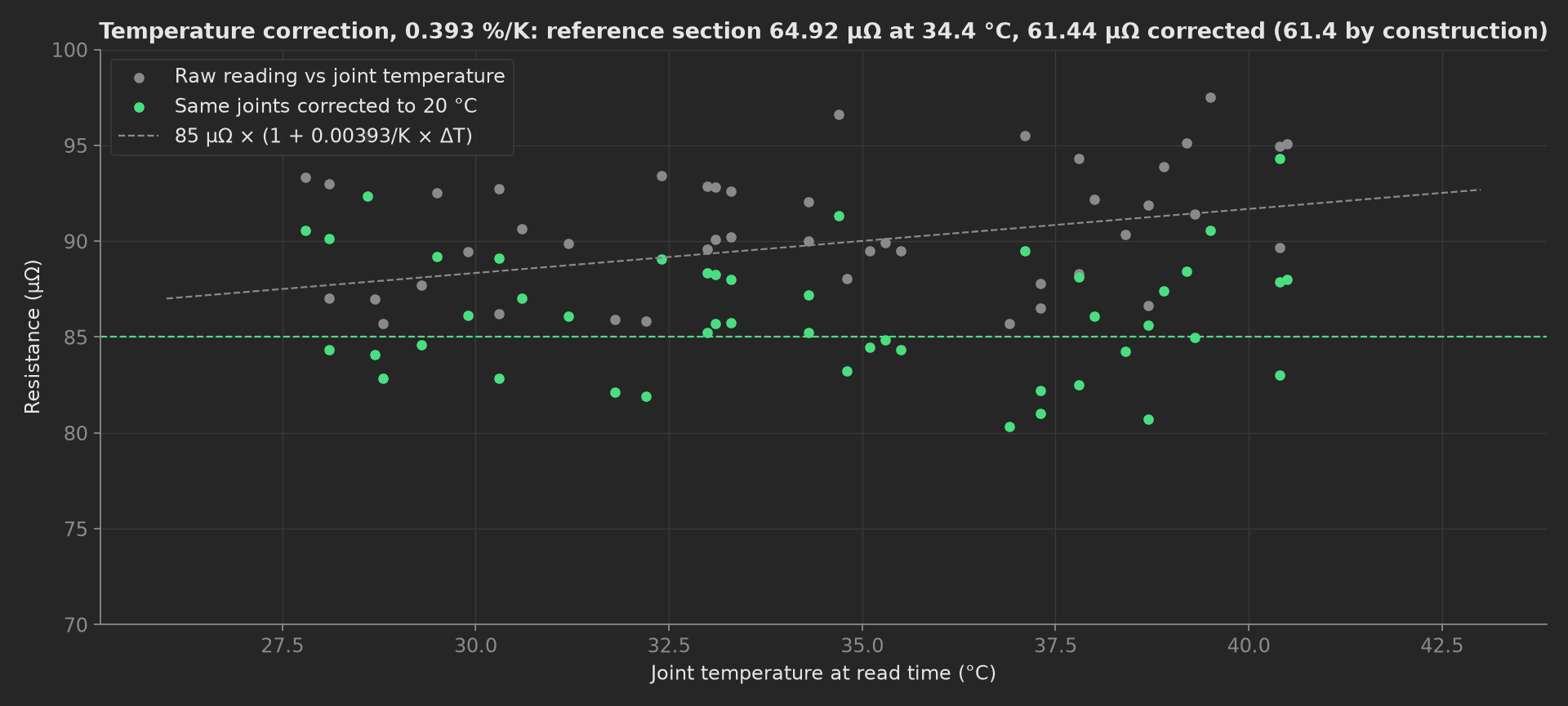
What the correction does across the module: the raw readings climb with the joint temperature along copper's coefficient, the corrected values sit flat around 85 µΩ whatever the joint's temperature was when the probe landed. The reference section, 64.92 µΩ at 34.4 °C, corrects to 61.44 µΩ against 61.4 by construction, inside the 0.5 % window.
Busbar Links
The 11 busbar-to-busbar joints of the series string, same method, corrected per link from the mean temperature of the two busbars they join. The sum is the module's series interconnect resistance, the number the pack's electrical model needs:
import numpy as npfrom utils.recipe import ALPHA_CU_PER_K, REFERENCE_TEMP_C, TEST_CURRENT_Adef busbar_links(measurements, meter, log): """The 11 busbar-to-busbar joints of the series string, same method.""" links = meter.measure_busbar_links(TEST_CURRENT_A) raw = np.array(links["raw_uohm"]) temp = np.array(links["temp_c"]) corrected = raw / (1.0 + ALPHA_CU_PER_K * (temp - REFERENCE_TEMP_C)) measurements.links.x_axis = links["link"] measurements.links.y_axis.corrected = corrected.round(2).tolist() measurements.links.y_axis.corrected.aggregations.max_uohm = float(corrected.max()) measurements.string_resistance_uohm = float(corrected.sum()) log.info(f"Series string: {corrected.sum():.0f} uOhm over {len(raw)} links, max link {corrected.max():.1f} uOhm")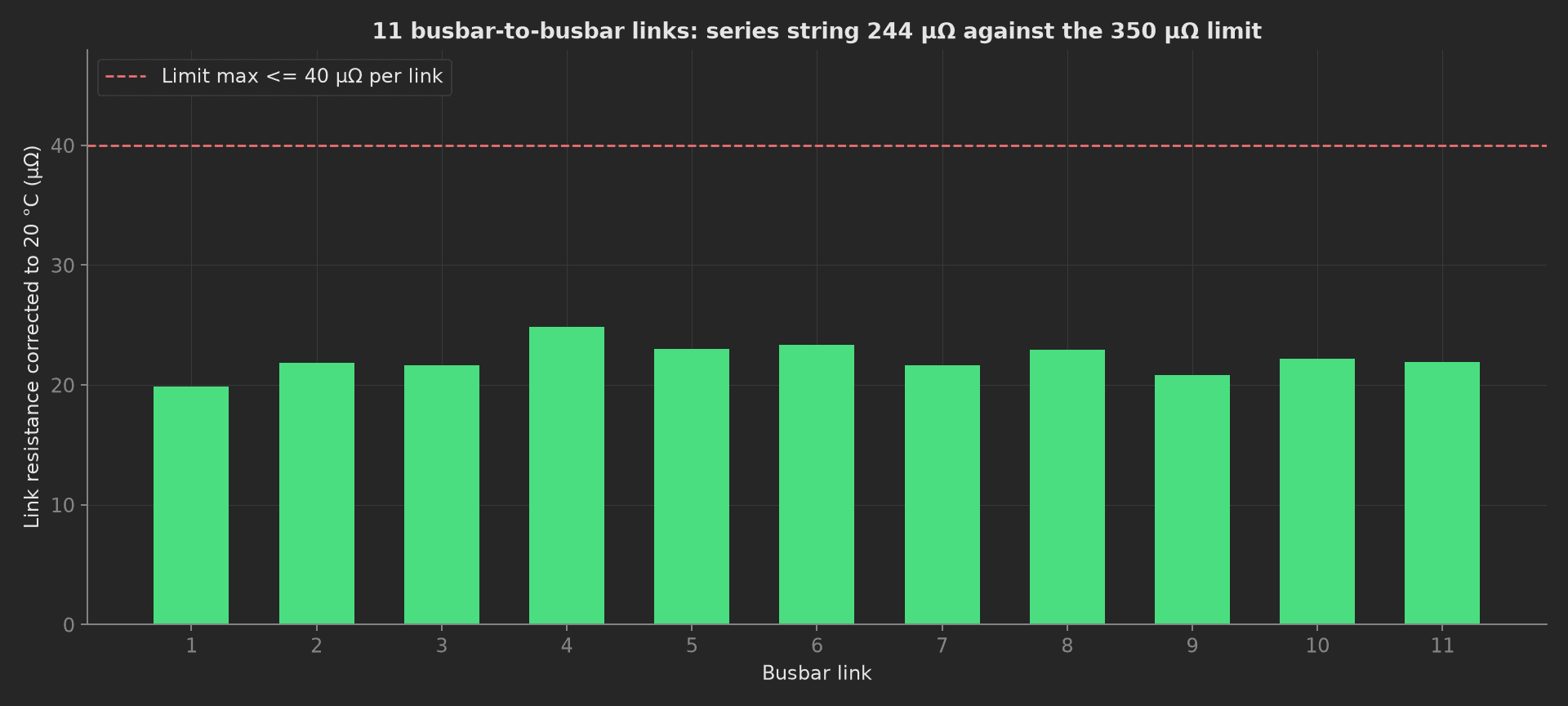
The eleven links of the mock module: 20 to 25 µΩ each, 244 µΩ for the string against the 350 µΩ limit. A link that reads double is a busbar seated on a burr or a bolt torqued short.
OVC Verification
Disabled by default. It reads the welds with OVC off and on, and reports how much the thermoelectric EMF of the copper-nickel-steel joint shifts the readings; on the mock, 4.2 µV/K of Seebeck coefficient at joints 8 to 20 K above ambient gives shifts of tens of micro-ohms, larger than the difference between a good weld and a shallow one. Run it when the probe head or the meter changes:
import numpy as npfrom utils.recipe import TEST_CURRENT_Adef ovc_verification(measurements, meter, log): """Disabled by default. Reads the welds with OVC off and reports how much the copper-aluminium thermoelectric EMF shifts the result; run it when the probe head or the meter is changed, not on every module.""" meter.set_ovc(False) no_ovc = np.array(meter.measure_welds(TEST_CURRENT_A)["raw_uohm"]) meter.set_ovc(True) with_ovc = np.array(meter.measure_welds(TEST_CURRENT_A)["raw_uohm"]) shift = no_ovc - with_ovc measurements.emf_shift_max_uohm = float(np.abs(shift).max()) log.info(f"Thermoelectric EMF shifts the reading by up to {np.abs(shift).max():.1f} uOhm without OVC")Mock Plug
MicroOhmMeter stands in for the meter, the multiplexer and the probe head's temperature sensor. It draws 48 welds around 85 µΩ at 20 °C with a 3.5 µΩ standard deviation, sets joint 30 to 140 µΩ, gives each busbar a temperature from 28 °C on the first to 41 °C on the last (the weld sequence), applies copper's 0.393 %/K to every raw reading, and adds a 4.2 µV/K thermoelectric EMF when OVC is off. The reference section is 61.4 µΩ at 20 °C, read at the mean joint temperature. Every method returns plain Python types because plug calls cross a JSON boundary; a measurement read back from measurements.<key> returns a proxy, so the phases keep locals for their log lines.
On a real station, the class speaks SCPI to a Hioki RM3546 over pyvisa (:SENS:RES:RANG 1E-3, :SENS:RES:OVC ON, :READ?), steps the multiplexer between joints, and reads the head's temperature sensor for each one. Keep OVC on for every dissimilar-metal joint, read the reference section through the second probe pair at the same moment as the welds, and set the coefficient for the busbar alloy (0.403 %/K for aluminium). The phases, measurements and limits stay the same.