

Get the complete source, dependencies and setup instructions from the template repository.
Open the source on GitHubIntroduction
Vibration in Drone Motors
Every BLDC motor on a drone produces vibration. Some is structural (rotor imbalance, bearing roughness), some is electromagnetic (cogging torque, commutation harmonics), and some is acoustic coupling from the frame itself. In flight, this vibration corrupts the IMU accelerometer readings that attitude estimation depends on: PX4's flight log analysis guidance treats anything above roughly 2-3 m/s² peak-to-peak on the accelerometer as strong vibration, and sustained levels beyond that cause attitude drift, position hold wander, and visual-inertial odometry failure. On gimballed cameras, residual vibration passes through the rolling shutter and renders "jello", a vertical wave artifact widely attributed to vibration passing through worn gimbal dampers (DJI advises replacing aged dampers because they "may affect shooting").
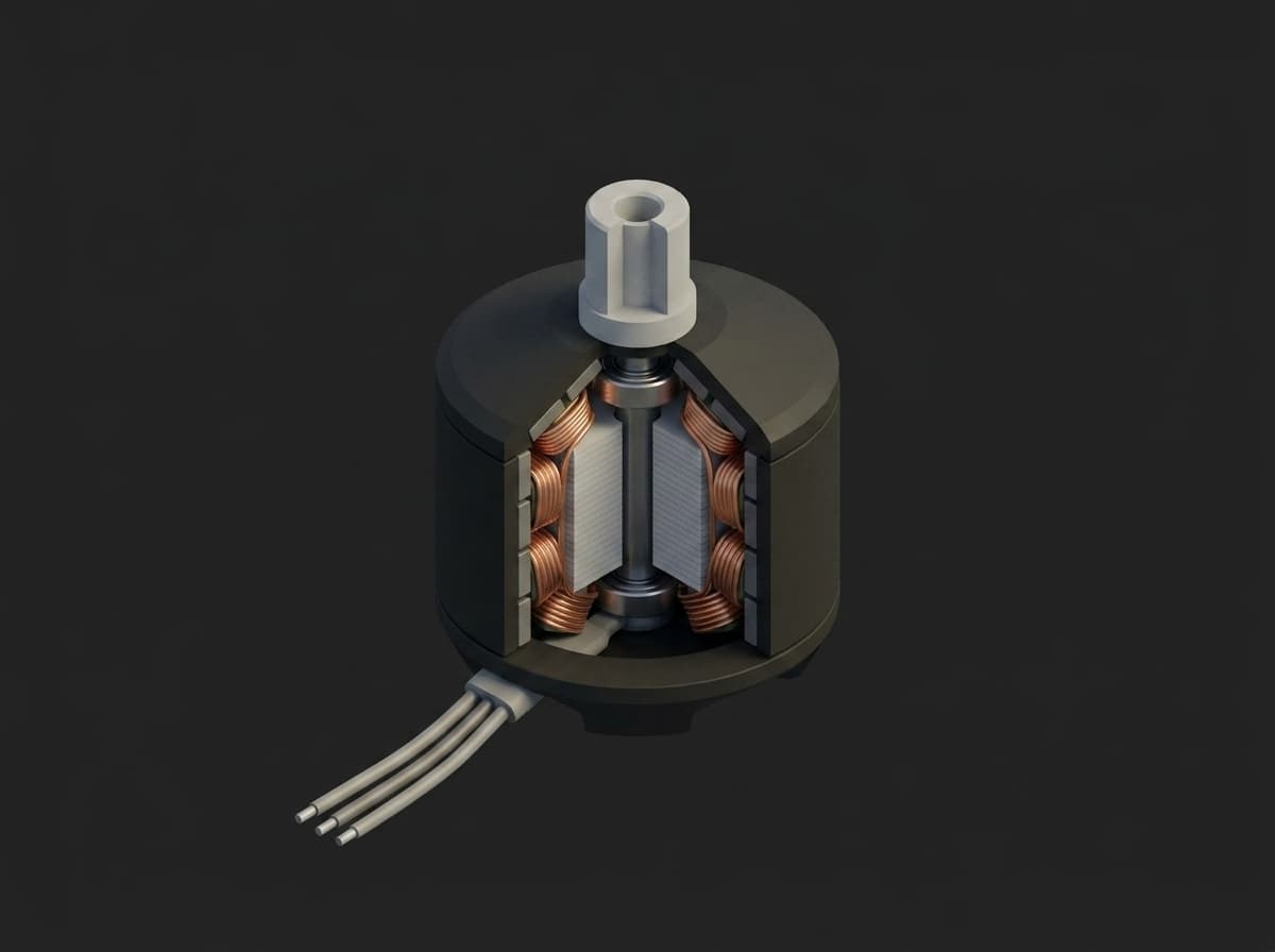
Imbalance lives in the bell and magnets, misalignment in the shaft, defect tones in the two bearings.
Continuous side-loading from imbalance also accelerates bearing race wear and damper fatigue over the airframe's life. End-of-line vibration testing catches the bad units before they ship and trends bearing supplier quality across the production batch.
Test Purpose
The procedure produces a per-motor vibration signature:
- 1× rotational order amplitude: static or dynamic imbalance (loose magnet, lost balance dot, deformed bell)
- 2× rotational order: misalignment, bent shaft
- Bearing defect bands: non-synchronous peaks at the outer-race (BPFO) and inner-race (BPFI) defect frequencies
- Broadband RMS across the sweep, and at hover RPM specifically
Comparing against a golden-reference fingerprint flags units with anomalous content. Production tightens the limits via TofuPilot's rolling 3σ analytics after the first 500-1000 units.
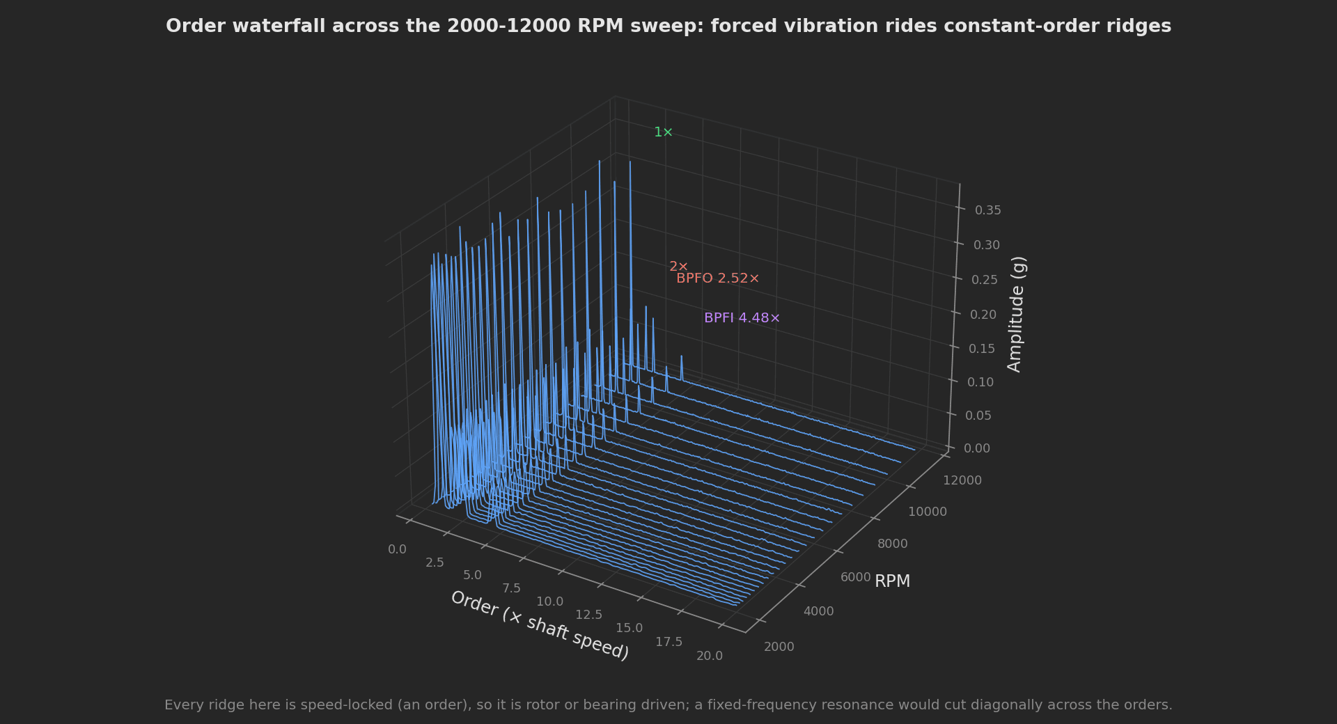
Order waterfall of the mock sweep: rotor and bearing content stays on its order across the whole RPM range, which is what separates it from a fixed-frequency structural resonance.
Equipment & Setup
To implement motor vibration testing on a production line, the following are required:
- A rigid steel motor fixture isolated from the bench, with an integrated tachometer pickup
- A triaxial accelerometer mounted to the motor stator or fixture
- A high-speed DAQ with anti-alias filtering
- The Device Under Test (DUT): motor only, prop must be removed for safety
- A programmable motor driver (same ESC + DShot as ESC characterization)
- A TofuPilot Framework procedure to step RPM, capture spectra, extract order peaks, and flag anomalies
- The TofuPilot Dashboard to log fingerprints and trend bearing supplier quality
Hardware Components
Accelerometer
The production reference is the PCB Piezotronics 356A32: a triaxial ICP/IEPE accelerometer, 100 mV/g, 1 Hz to 4 kHz band (±5%), 5 g titanium housing, sold on a quote basis. It is an industry standard for rotating-machinery diagnostics. For embedded in-airframe monitoring at lower cost, the Analog Devices ADXL355 (low-noise MEMS, 22.5 µg/√Hz on the ±2 g range, ±2/4/8 g selectable, ~$50) is the alternative.
The motor is tested without a propeller. The accelerometer measures fixture vibration and the optical pickup reads a marker on the rotating bell; drive electronics are omitted.
Mounting matters: in decreasing rigidity, stud, thin adhesive, beeswax, flat magnet, curved magnet. PCB's TN-5 mounting technote documents the bandwidth cost of each; a magnet mount can halve the usable frequency range. Wax is acceptable below ~1 kHz, magnet below ~2 kHz. For end-of-line testing requiring fast swap, a magnet-mounted sensor on a steel fixture is the practical compromise. For permanent reference benches, stud-mount.
DAQ
The NI-9234 C Series module (in a cDAQ chassis) is the reference: 4 channels IEPE, 24-bit, 51.2 kS/s/ch, software-selectable 2 mA IEPE current, automatic anti-alias filter tracking the sample rate. Dewesoft and Brüel & Kjær offer production-line analyzers with built-in order-tracking workflows. For higher channel counts (multiple motors in parallel), a cDAQ-9189 chassis with multiple NI-9234 modules scales linearly.
Motor Fixture
A machined steel block bolted to a vibration-isolated bench (concrete floor or vibration-isolation table). The motor mounts on a flange with a stud-mount accelerometer pickup on the stator. The fixture's natural modes must be above 5 kHz (verified by impact hammer test) so they don't contaminate the motor signature. Mass typically 5-10 kg.
Custom Firmware
ESC under bidirectional DShot, same as the throttle-to-RPM characterization test. The test station commands RPM directly via DShot frames and reads back eRPM telemetry as the speed reference. Because the sweep dwells at fixed RPM steps, a windowed FFT per step gives clean order peaks; continuous sweeps would need angular-domain order tracking instead.
Test Procedure
Overview
After mounting the motor (prop removed) and connecting accelerometer + DAQ + ESC, the procedure runs:
- Safety gate: the operator confirms prop removal on a switch; the run refuses to continue otherwise.
- Step RPM from 2000 to 12000 in 50 logarithmic steps, acquiring 200 ms at 10 kHz per step.
- Compute a Hann-windowed FFT per step and extract the 1×, 2×, BPFO, and BPFI peaks.
- Validate every metric against per-axis limits.
- Record the hover-RPM spectrum and the 1× trace as interactive charts, attach the metrics CSV.
- Stream results to TofuPilot for traceability and analytics.
This template exercises several framework capabilities on purpose: an operator UI safety gate bound to a boolean measurement, multi-dimensional measurements with per-axis aggregations, file attachments, multi-slot execution for testing four motor arms in parallel, and all four log levels.
Why TofuPilot Framework?
TofuPilot Framework is a YAML + Python test framework built for hardware manufacturing. Instead of writing all your test logic, measurements, and limits inside Python code, you describe what the test does in a procedure.yaml file, and how in small Python phase files. The framework handles:
- Automatic Python environment management (via
uv) - Operator UI (no frontend code needed)
- Measurement validation and live charts
- Process isolation between phases and equipment plugs
Project Structure
You can find the full source on GitHub. The mock DAQ plug synthesizes captures in code, so the procedure runs end to end without hardware:
tofupilot run . --ui-values ui.jsonui.json pre-bakes the operator confirmation for headless runs; on a station the operator flips the switch instead.
The Procedure File
procedure.yaml declares the unit, the DAQ plug, three phases wired with depends_on, and every measurement with its limits. This is the exact file from the repository:
procedure.yaml135 lines
name: Motor Balance and Vibration Signatureversion: 0.1.0description: Per-motor vibration fingerprint across an RPM sweep with order extraction, bearing defect detection, and interactive spectrum charts.execution: workers: 8 strategy: phase_first # Multi-slot parallel testing: uncomment to test all four motor arms at # once on a station (one dashboard run per slot). The one-shot CLI path # (`tofupilot run`) does not support multi-slot yet, so the local template # runs single-slot. # slots: # - name: ARM1 # - name: ARM2 # - name: ARM3 # - name: ARM4unit: auto_identify: true serial_number: default_value: "SN-MOTOR-0001" part_number: default_value: "MOTOR-2207"plugs: - name: DAQ key: daq description: Mock IEPE DAQ that synthesizes an accelerometer capture per RPM step. python: plugs.daq:MockDaqmain: - name: Safety Check key: safety_check python: phases.safety_check ui: requires_input: true components: - key: prop_removed type: switch label: "Propeller removed" description: "Confirm the propeller is removed before the motor is energized" bind: measurements.prop_removed measurements: - name: Prop Removed key: prop_removed description: Operator confirmation that no propeller is installed. validators: - operator: "==" expected_value: true - name: RPM Sweep key: rpm_sweep python: phases.rpm_sweep depends_on: [safety_check] measurements: - name: Steps Acquired key: steps_acquired validators: - operator: "==" expected_value: 50 - name: Vibration Analysis key: vibration_analysis python: phases.vibration_analysis depends_on: [rpm_sweep] measurements: - name: 1x Peak Amplitude key: one_x_amplitude unit: g description: Rotational-order peak, dominated by rotor imbalance. validators: - operator: "<=" expected_value: 0.8 - name: 2x Peak Amplitude key: two_x_amplitude unit: g description: Second-order peak, dominated by misalignment or a bent shaft. validators: - operator: "<=" expected_value: 0.4 - name: BPFO Amplitude key: bpfo_amplitude unit: g description: Outer-race bearing defect band amplitude. validators: - operator: "<=" expected_value: 0.2 - name: BPFI Amplitude key: bpfi_amplitude unit: g description: Inner-race bearing defect band amplitude. validators: - operator: "<=" expected_value: 0.2 - name: Hover Band RMS key: hover_rms unit: g description: Broadband RMS in the 5000-7000 RPM hover band. validators: - operator: "<=" expected_value: 0.5 - name: Full Sweep RMS key: sweep_rms unit: g validators: - operator: "<=" expected_value: 1.5 - name: Hover Spectrum key: hover_spectrum title: Spectrum at hover RPM description: Amplitude spectrum at the sweep step closest to 6000 RPM, rendered as an interactive chart by the dashboard. x_axis: legend: Frequency unit: Hz y_axis: - legend: Amplitude key: amplitude unit: g - name: 1x Order Trace key: one_x_trace title: 1x amplitude vs RPM description: Rotational-order amplitude across the sweep. A flat trace is a balanced rotor; a rising trace tracks imbalance with speed. x_axis: legend: RPM unit: rpm y_axis: - legend: 1x Amplitude key: one_x unit: g aggregations: - type: p2p unit: g validators: - operator: "<=" expected_value: 0.5The slots block is the multi-slot showcase: uncommented on a station engine, the same procedure tests all four motor arms in parallel, producing one dashboard run per slot. The one-shot CLI path does not support multi-slot yet, so the local template runs single-slot. The workers: 8 and strategy: phase_first settings control how many phases run concurrently and, on a multi-slot station, whether each phase completes across all slots before the next phase starts.
Where do the limits come from? The hover-band RMS limit (0.5 g ≈ 4.9 m/s²) is set so a motor passing the test contributes well under the 2-3 m/s² peak-to-peak accelerometer disturbance that PX4 flags as strong vibration once frame damping is accounted for. The order and bearing-band limits start as fractions of that budget, in the spirit of the zone classification that ISO 20816-1 (which replaced ISO 10816-1) applies to machine vibration severity, and are then tightened to the observed production 3σ once a few hundred units have run.
Safety Gate
The first phase is an operator UI gate. A switch component is bound to the prop_removed boolean measurement with bind, and requires_input: true forces a Continue click. The == true validator fails the phase if the operator does not confirm, so the motor is never energized with a prop installed:
def safety_check(log): """Operator gate: the bound switch writes measurements.prop_removed. The phase passes only if the operator confirms the propeller is removed; the validator `== true` fails the phase otherwise and the run stops before the motor is ever energized. """ log.info("Waiting for operator confirmation that the propeller is removed")No Python is needed to read the switch: the binding writes the operator's answer straight into the measurement, and the validator does the enforcement.
RPM Sweep
50 logarithmic RPM steps from 2000 to 12000 RPM, 200 ms at 10 kHz per step. Logarithmic spacing concentrates resolution where it matters: low-RPM bearing pre-failure indicators and high-RPM resonance. The sweep phase drives the DAQ plug and validates the step count:
RPM_START = 2000RPM_END = 12000STEPS = 50def rpm_sweep(daq, measurements, log): log.debug(f"Commanding sweep {RPM_START}-{RPM_END} RPM in {STEPS} log steps") rpms = daq.acquire_sweep(RPM_START, RPM_END, STEPS) if len(rpms) < STEPS: log.warning(f"Sweep returned {len(rpms)} steps, expected {STEPS}") measurements.steps_acquired = len(rpms) log.info(f"Acquired {len(rpms)} captures from {rpms[0]} to {rpms[-1]} RPM")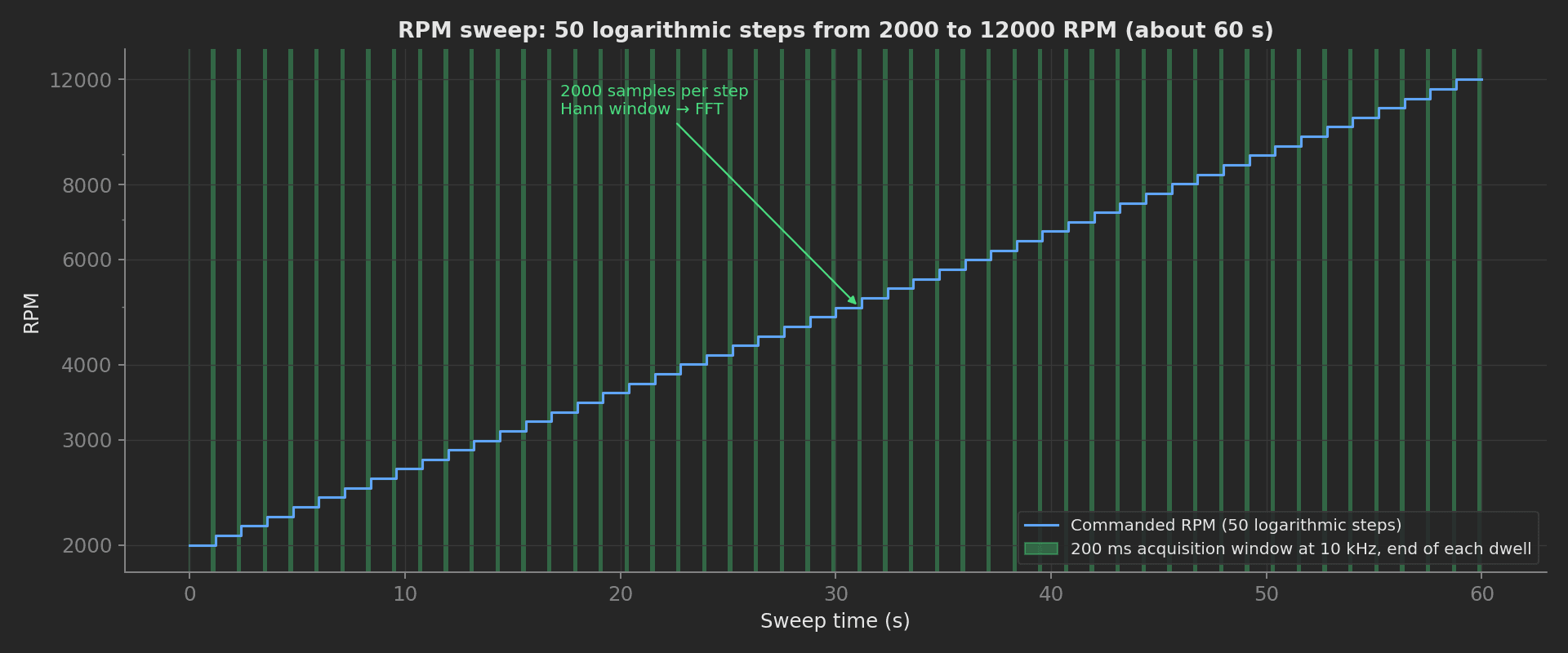
Each dwell ends with a 200 ms capture; the logarithmic spacing packs more steps into the low-RPM range.
The plug caches each capture so the analysis phase can fetch it later. The mock synthesizes a realistic signal (1× imbalance, 2× misalignment, bearing tones, broadband noise). Critically, it injects the bearing tones at the same BPFO/BPFI frequencies the analysis searches, using the shared geometry in utils/bearing.py, so the detection path is genuinely exercised: raising the injected outer-race tone above 0.2 g makes the run fail on the bpfo_amplitude validator. Swap the class for one wrapping nidaqmx and your ESC driver to run on real hardware:
plugs/daq.py52 lines
import mathimport randomfrom utils.bearing import bearing_defect_frequenciesclass MockDaq: """Simulated DAQ. Synthesizes one accelerometer capture per RPM step. A real implementation would wrap nidaqmx and command the ESC over bidirectional DShot; the interface below stays identical. The bearing tones are injected at the same BPFO/BPFI frequencies the analysis phase searches, from the shared geometry in utils/bearing.py. """ SAMPLE_RATE_HZ = 10_000 CAPTURE_S = 0.2 def __init__(self): self._captures = {} random.seed(2207) print("Mock DAQ initialized (10 kHz, 200 ms per step)") def acquire_sweep(self, rpm_start, rpm_end, steps): """Run the RPM sweep and cache one capture per step. Returns step RPMs.""" rpms = [ rpm_start * (rpm_end / rpm_start) ** (i / (steps - 1)) for i in range(steps) ] for rpm in rpms: self._captures[round(rpm)] = self._synthesize(rpm) return [round(r) for r in rpms] def get_capture(self, rpm): """Return the cached capture for one RPM step as a list of floats.""" return self._captures[rpm] def _synthesize(self, rpm): f_r = rpm / 60.0 n = int(self.SAMPLE_RATE_HZ * self.CAPTURE_S) dt = 1.0 / self.SAMPLE_RATE_HZ defects = bearing_defect_frequencies(f_r) samples = [] for i in range(n): t = i * dt v = 0.38 * math.sin(2 * math.pi * f_r * t) # 1x imbalance v += 0.14 * math.sin(2 * math.pi * 2 * f_r * t) # 2x misalignment v += 0.12 * math.sin(2 * math.pi * defects["bpfo"] * t) # outer race tone v += 0.06 * math.sin(2 * math.pi * defects["bpfi"] * t) # inner race tone v += random.gauss(0.0, 0.02) # broadband noise samples.append(v) return samplesBearing Defect Frequencies
Per the standard rolling-element formulas (see for example Timken's bearing frequency guide), with N balls, ball diameter d, pitch diameter D, contact angle φ, shaft speed f_r:
- BPFO = (N/2) · f_r · (1 − (d/D) cos φ)
- BPFI = (N/2) · f_r · (1 + (d/D) cos φ)
- BSF = (D/(2d)) · f_r · (1 − ((d/D) cos φ)²)
- FTF = (1/2) · f_r · (1 − (d/D) cos φ)
The template validates the two highest-signal bands, BPFO and BPFI; the utility also computes BSF and FTF for production lines that trend cage and ball defects. The geometry constants live in one place, imported by both the mock and the analysis, so injected tones and search windows can never drift apart:
# Bearing geometry for the motor's 7-ball deep-groove bearing (per motor# model, loaded from a spec in production). The mock DAQ and the analysis# phase both import these so the injected tones and the search windows can# never drift apart.N_BALLS = 7D_OVER_DP = 0.28def bearing_defect_frequencies(f_r, n_balls=N_BALLS, d_over_dp=D_OVER_DP, cos_phi=1.0): """Rolling-element defect frequencies for shaft speed f_r in Hz.""" ratio = d_over_dp * cos_phi return { "bpfo": (n_balls / 2.0) * f_r * (1.0 - ratio), "bpfi": (n_balls / 2.0) * f_r * (1.0 + ratio), "bsf": (1.0 / (2.0 * d_over_dp)) * f_r * (1.0 - ratio**2), "ftf": 0.5 * f_r * (1.0 - ratio), }With this 7-ball, d/D = 0.28 geometry at 6000 RPM (f_r = 100 Hz): BPFO = 252 Hz, BPFI = 448 Hz.
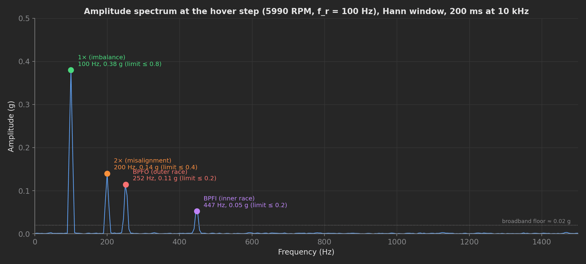
Hover-step spectrum of the mock capture: every peak the analysis validates, each against its limit.
Vibration Analysis
The analysis phase computes a windowed FFT per step, extracts the order and bearing-band peaks, fills the two interactive charts, and attaches the per-step metrics as a CSV. It also reads the previous phase's result through previous-results injection: naming a parameter rpm_sweep gives read access to that phase's measurements:
phases/vibration_analysis.py92 lines
import osimport tempfileimport numpy as npfrom utils.bearing import bearing_defect_frequenciesSAMPLE_RATE = 10_000HOVER_BAND = (5000, 7000)def _peak_near(freqs, spectrum, target_hz, tolerance_bins=3): idx = int(np.argmin(np.abs(freqs - target_hz))) lo = max(0, idx - tolerance_bins) hi = min(len(spectrum), idx + tolerance_bins + 1) return float(np.max(spectrum[lo:hi]))def vibration_analysis(daq, rpm_sweep, measurements, attach, log): steps = int(rpm_sweep.steps_acquired) log.debug(f"Analyzing {steps} captures from the sweep phase") rpms = [ 2000 * (12000 / 2000) ** (i / (steps - 1)) for i in range(steps) ] rpms = [round(r) for r in rpms] spectra = [] one_x, two_x, bpfo_amp, bpfi_amp, rms_all = [], [], [], [], [] freqs = None for rpm in rpms: samples = np.asarray(daq.get_capture(rpm)) window = np.hanning(len(samples)) spectrum = np.abs(np.fft.rfft(samples * window)) * 2.0 / np.sum(window) freqs = np.fft.rfftfreq(len(samples), 1.0 / SAMPLE_RATE) spectra.append(spectrum) f_r = rpm / 60.0 defects = bearing_defect_frequencies(f_r) one_x.append(_peak_near(freqs, spectrum, f_r)) two_x.append(_peak_near(freqs, spectrum, 2 * f_r)) bpfo_amp.append(_peak_near(freqs, spectrum, defects["bpfo"])) bpfi_amp.append(_peak_near(freqs, spectrum, defects["bpfi"])) rms_all.append(float(np.sqrt(np.mean(samples**2)))) hover = [r for r, rpm in zip(rms_all, rpms) if HOVER_BAND[0] <= rpm <= HOVER_BAND[1]] if not hover: log.warning("No sweep step fell inside the hover band, using nearest step") hover = [rms_all[int(np.argmin(np.abs(np.asarray(rpms) - 6000)))]] measurements.one_x_amplitude = max(one_x) measurements.two_x_amplitude = max(two_x) measurements.bpfo_amplitude = max(bpfo_amp) measurements.bpfi_amplitude = max(bpfi_amp) measurements.hover_rms = max(hover) measurements.sweep_rms = max(rms_all) if max(bpfo_amp) > 0.18: log.error( f"BPFO amplitude {max(bpfo_amp):.3f} g at the 0.2 g limit, " "suspect a damaged outer race" ) elif max(bpfo_amp) > 0.1: log.warning( f"BPFO amplitude {max(bpfo_amp):.3f} g above the 0.1 g watch level, " "trend the bearing supplier lot" ) hover_idx = int(np.argmin(np.abs(np.asarray(rpms) - 6000))) hover_spec = spectra[hover_idx] keep = freqs <= 1500.0 measurements.hover_spectrum.x_axis = freqs[keep].tolist() measurements.hover_spectrum.y_axis.amplitude = hover_spec[keep].tolist() measurements.one_x_trace.x_axis = [float(r) for r in rpms] measurements.one_x_trace.y_axis.one_x = one_x aggs = measurements.one_x_trace.y_axis.one_x.aggregations aggs.p2p = float(max(one_x) - min(one_x)) csv_path = os.path.join(tempfile.gettempdir(), "sweep_metrics.csv") table = np.column_stack([rpms, one_x, two_x, bpfo_amp, bpfi_amp, rms_all]) np.savetxt( csv_path, table, delimiter=",", header="rpm,one_x_g,two_x_g,bpfo_g,bpfi_g,rms_g", comments="", fmt="%.6f", ) attach.file(csv_path, "sweep_metrics.csv") log.info("Sweep metrics CSV attached, analysis complete")The log levels are used deliberately: debug for internals, info for milestones, warning when the BPFO amplitude crosses a watch level below the limit, and error when it reaches the limit itself. The mock's injected outer-race tone sits at 0.12 g, above the 0.1 g watch level, so the warning fires on every reference run and the run still passes.
Interactive Charts Instead of Plot Files
hover_spectrum and one_x_trace are multi-dimensional measurements. The dashboard renders them as interactive charts directly from the declared axes, so no plotting library is needed and no PNG is generated. The 1× trace carries a p2p aggregation with its own validator: a rotor whose 1× amplitude swings more than 0.5 g across the sweep fails even if every individual point is in spec. The raw per-step metrics attach as sweep_metrics.csv via attach.file() for offline analysis.
The headless input file used by the CI run is one line:
{"safety_check": {"prop_removed": true}}