
Get the complete source, dependencies and setup instructions from the template repository.
Open the source on GitHubIntroduction
BMS PCBA Test Overview
A battery management system board only does anything when it believes it is wired to a pack. Every cell-sense input expects a voltage in the 2 to 4.5 V window, stacked on top of the channel below it, so the top of a 16S board sits at 60 V above the bottom. A production functional test therefore starts with a battery cell simulator: one isolated, programmable channel per cell input, each able to source and sink current, stacked in series to reproduce the pack's common-mode ladder. With the pack replaced by a simulator, the tester reaches states a real pack might not reach in years (one cell at over-voltage next to one at under-voltage, an open sense wire, every channel at a distinct voltage) in seconds, and without a lithium cell inside the fixture.
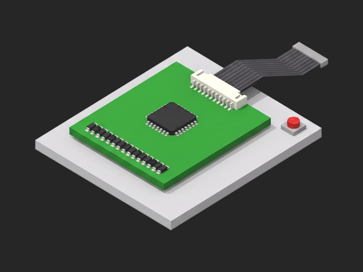
A 16S BMS PCBA in the fixture: the cell-sense connector carries sixteen taps plus the stack return, the analog front end reads them, and the row of bleed resistors next to it is the balancing path this template borrows to measure each tap's resistance.
The analog front end (AFE) that reads the cells is specified to a few millivolts. The TI BQ79616 main ADC, for instance, is guaranteed to -2.2/+1.5 mV at 25 °C and -3.0/+2.4 mV from -20 to 65 °C for cells between 2 and 4.5 V (see the BQ79616 datasheet, VACC_MAIN_CELL). The ADI ADBMS6815 claims better than 1.5 mV lifetime total measurement error. Everything downstream of the AFE, the divider or filter resistors on each input, the sense harness, the connector, the solder joints, the calibration constants written at the end of the line, is the board assembler's responsibility, and this is what the functional test proves.
Test Purpose
The procedure records one functional fingerprint per board:
- Identity and configuration: firmware version, AFE part and cell count, CRC of the protection configuration block, all read over the service port
- Cell voltage accuracy on a monotonic staircase, per channel, against the simulator's own readback
- Channel order: a crossed pair in the sense harness breaks the staircase
- Gain error and offset per channel from a three-point sweep
- Open-wire detection: one channel opened, the DUT must flag the wire, and the fault map must be clean once reconnected
- Sense tap resistance per channel, measured through the bleed path
- Ship-mode current of the whole stack on the simulator's 250 µA range
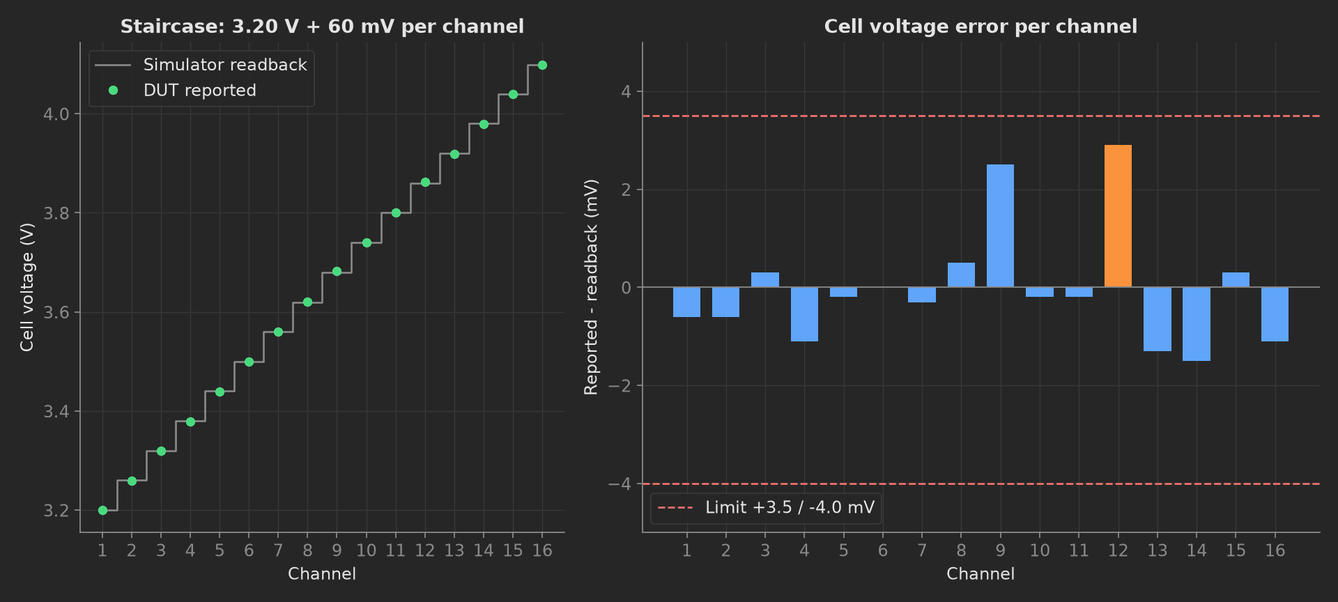
The mock board on the staircase: every channel reads its own step, the order is intact, and the error per channel stays inside the asymmetric -4.0/+3.5 mV window with channel 12 closest to the limit at +2.9 mV.
The framework mechanics on show are the setup and teardown stages, string and JSON validators (matches on the firmware version, == on a whole identity object), multi-dimensional measurements with custom aggregations validated in YAML, asymmetric limits, a sequential depends_on chain on one shared bench, and a plug config block that becomes constructor arguments.
Equipment & Setup
To run this functional test on a production line, the following are required:
- A battery cell simulator with one isolated channel per cell input, four-quadrant, four-wire sense
- A service link to the DUT (UART, I²C or CAN, whatever the board exposes for calibration)
- A pogo-pin fixture with Kelvin contacts on every cell-sense point
- The Device Under Test (DUT): a 16S BMS PCBA with its production firmware
- A TofuPilot Framework procedure to script the sequence, log the per-channel data and validate the limits
- The TofuPilot Dashboard to store the per-board results for traceability and per-channel trending
Hardware Components
Cell Simulator
The Chroma 87001 is the reference for this class: 16 channels, 0 to 5 V, bidirectional up to 5 A, setting accuracy ±0.02 % of full scale (±1 mV) with 0.5 mV setting resolution, readback accuracy ±0.02 % of full scale with 0.1 mV resolution, 1000 V channel-to-channel and channel-to-ground isolation, and units stackable to 240S2P below 1000 V. Two of its current ranges are designed for this exact test: 0 to 500 mA at ±100 µA for passive balancing current, and 0 to 250 µA for the quiescent draw of the cell-supervision circuit. The Keysight SL1010A-803 goes further on accuracy (±0.2 mV offset + 0.01 % of value, and it states that setting and measuring accuracy are identical) at ±5 A per channel. The dSPACE EV1077 holds ±0.5 mV over its whole working temperature range but only isolates 60 V between the cells of one module, so a 16S stack spans several modules.
Two instruments sold for BMS test sit five to seven times looser: the Pickering 41-752A at ±5 mV setting, ±7 mV typical readback, and only over 11 to 31 °C, and the Bloomy BS-1200 at ±3 mV with remote sense required. A ±3 mV simulator cannot police a ±3 mV limit. The limits in this template assume a Chroma or Keysight class instrument; with a Pickering or Bloomy, widen the windows and say so in the procedure.
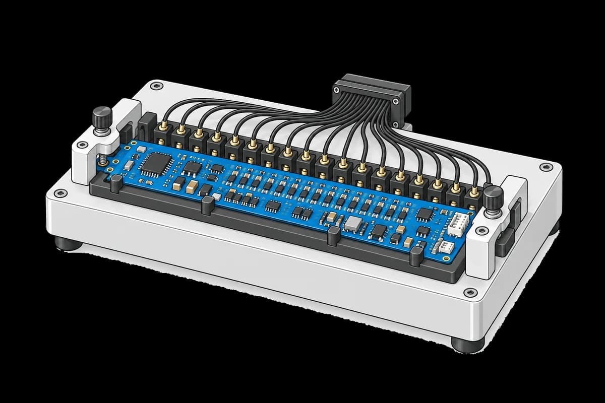
The fixture supports the BMS board and its individual cell-sense connections. The cell simulator and test computer connect externally and are not shown.
Fixture and Kelvin Sense
Every cell-sense point needs a four-wire contact. Two-wire probing folds pogo-pin and harness resistance into the forced voltage; at the tens of milliohms typical of a worn pin and the milliamps an AFE input draws that is small, but during the tap-resistance phase 80 mA flows through the same path and the error becomes the measurement. NI's production BMS test brief states the achieved figure plainly: four-wire Kelvin contacts on the cell voltage sense points are what get the fixture to sub-millivolt accuracy. Keep the simulator's own readback, taken at the sense pins, as the truth; the setpoint is what you asked for, the readback is what the DUT actually saw.
Never build the cell ladder from a resistor divider across one supply. TI devotes a section of SLUAA81A to why: the moment one channel balances, its bleed current collapses the divider, the neighbouring inputs move, the over-voltage protection trips, balancing is disabled, and on some parts a permanent-fail bit is set. That is a scrapped board, not a failed test.
Where the Limits Come From
No standard specifies a BMS PCBA production test. IEC 62619, IEC 62133, UL 2054 and UL 1973 test cells, batteries and battery systems by outcome; ISO 26262-7 mandates that a safety-related characteristic is controlled in production and that the evidence is kept, but it does not hand out a millivolt. The limits therefore come from the AFE datasheet, widened by the simulator's accuracy. The staircase window below is the BQ79616's -3.0/+2.4 mV row for -20 to 65 °C plus ±1 mV of simulator, rounded to -4.0/+3.5 mV. It is asymmetric because the datasheet is asymmetric; a symmetric ±3.5 mV window would throw away yield on the negative side for no reason. The tap resistance limit of 150 mΩ and the ship current limit of 250 µA are internal specifications of the mock board and are the kind of number a customer sets from their own harness and AFE, not from a standard.
Test Procedure
Overview
The procedure maps the sequence onto the framework's three stages. Identity lives in setup: so no accuracy number is recorded against a board running the wrong firmware. Parking the board lives in teardown: so it runs even when a main phase fails and no board is left with a bleed path on.
- Setup: pack to 3.6 V/cell, identity block, config CRC.
- Main: staircase, per-channel error, channel order.
- Main: three-point sweep, gain error and offset per channel.
- Main: one channel opened, open-wire flag, fault map after reconnect.
- Main: bleed current through each tap, series resistance per channel.
- Teardown: ship mode, quiescent draw, outputs off.
Every metric validates against limits declared in procedure.yaml, and results stream to TofuPilot for traceability and per-channel trending.
Why TofuPilot Framework?
TofuPilot Framework is a YAML + Python test framework built for hardware manufacturing. Instead of writing all your test logic, measurements, and limits inside Python code, you describe what the test does in a procedure.yaml file, and how in small Python phase files. The framework handles:
- Automatic Python environment management (via
uv) - Operator UI (no frontend code needed)
- Measurement validation and live charts
- Process isolation between phases and equipment plugs
Project Structure
You can find the full source on GitHub. The BmsBench plug is a mock of the simulator and the DUT's service port together, synthesizing a healthy 16S board with one channel near the offset limit and one sense tap with a marginal crimp, so the procedure runs end-to-end without a simulator or a board connected.
tofupilot run .For CI or bench automation, the same run executes headless:
tofupilot run . --no-tui --no-kiosk --jsonThe Procedure File
procedure.yaml declares the unit (scanned data-matrix with a pattern), the bench plug with its config passed as constructor arguments, and the three stages with every measurement and limit:
procedure.yaml167 lines
name: BMS Cell Simulator Functional Testversion: 0.1.0description: Functional test of a 16S BMS PCBA on a battery cell simulator. Identity and config readback, per-channel voltage accuracy on a staircase, gain and offset from a three-point sweep, open-wire detection, sense tap resistance, ship-mode current.unit: auto_identify: true serial_number: description: "Scan the board data-matrix before it goes into the fixture" placeholder: "BMS16-00000" pattern: "^BMS16-\\d{5}$" default_value: "BMS16-01742" part_number: default_value: "PCB-BMS-16S-R3" batch_number: default_value: "LOT-2026-37"plugs: - name: BMS Bench description: "16-channel cell simulator and DUT UART link (mock Chroma 87001-class, one plug per bench)" python: plugs.bms_bench:BmsBench key: bench config: cell_count: 16 bleed_ma: 80setup: - name: Identify DUT key: identify_dut python: phases.identify_dut measurements: - name: Firmware Version key: firmware_version description: Production firmware line is 2.x; a 1.x board was flashed from the wrong release. validators: - {operator: matches, expected_value: "^2\\.\\d+\\.\\d+$"} - name: AFE Identity key: afe_identity description: AFE part and cell count as one object; a 3S variant of the same PCB must fail here. validators: - operator: "==" expected_value: afe: BQ76952 cell_count: 16 - name: Config CRC key: config_crc description: CRC of the protection configuration block, must match the released config. validators: - {operator: "==", expected_value: "0x3A7F"}main: - name: Cell Voltage Accuracy key: cell_voltage_accuracy python: phases.cell_voltage_accuracy measurements: - name: Staircase key: staircase title: Reported vs simulator readback per channel x_axis: legend: Channel y_axis: - legend: Forced key: forced unit: mV - legend: Reported key: reported unit: mV - legend: Error key: error unit: mV aggregations: - type: max_mv unit: mV validators: - {operator: "<=", expected_value: 3.5} - type: min_mv unit: mV validators: - {operator: ">=", expected_value: -4.0} - name: Channel Order key: order_ok description: Readback rises with channel index; a crossed pair in the sense harness breaks it. validators: - {operator: "==", expected_value: true} - name: Gain Offset Sweep key: gain_offset_sweep python: phases.gain_offset_sweep depends_on: [cell_voltage_accuracy] measurements: - name: Linearity key: linearity title: Gain error and offset per channel from a 3-point sweep x_axis: legend: Channel y_axis: - legend: Gain error key: gain_err unit: "%" aggregations: - type: max_abs_pct unit: "%" validators: - {operator: "<=", expected_value: 0.10} - legend: Offset key: offset unit: mV aggregations: - type: max_abs_mv unit: mV validators: - {operator: "<=", expected_value: 3.0} - name: Open Wire Check key: open_wire_check python: phases.open_wire_check depends_on: [gain_offset_sweep] measurements: - name: Open Wire Flagged key: open_wire_flagged description: The DUT must raise the open-wire fault for the opened channel, not report a plausible voltage. validators: - {operator: "==", expected_value: true} - name: Open Wire Reading key: open_wire_reading_mv unit: mV description: What the AFE reads on the floating input, recorded for trending, no limit. - name: Faults After Reconnect key: faults_after_reconnect validators: - operator: "==" expected_value: open_wire: [] ov: [] uv: [] - name: Tap Resistance key: tap_resistance python: phases.tap_resistance depends_on: [open_wire_check] timeout: 60s measurements: - name: Tap Path key: tap_path title: Sense tap series resistance per channel x_axis: legend: Channel y_axis: - legend: Resistance key: resistance unit: mΩ aggregations: - type: max_mohm unit: mΩ validators: - {operator: "<=", expected_value: 150.0}teardown: - name: Shutdown key: shutdown python: phases.shutdown measurements: - name: Ship Current key: ship_current_ua unit: µA description: Stack draw in ship mode on the simulator's 250 uA range; a stuck balancing FET or a wrong pull-up shows here. validators: - {operator: "<=", expected_value: 250.0}Framework features to notice:
- String and JSON validators.
firmware_versionvalidates withmatchesagainst a regex,config_crcwith==on a string, andafe_identitywith==on a whole object, so a 3S variant of the same PCB fails at setup with the reason in the report. - Aggregations validated in YAML. The staircase records three curves; the pass/fail lives on two aggregations of the error curve,
max_mvandmin_mv, computed in Python and named in the procedure file with their own limits. - Asymmetric limits.
<= 3.5and>= -4.0on the same aggregation pair, copied from the AFE datasheet row rather than a single ± number. - One bench, one chain. Every main phase declares
depends_onon the previous one because they share the simulator; without the chain the framework would run them concurrently and the readings would interleave. teardown:always runs. The board ends in ship mode and the outputs go off whether the main phases passed or not.
Identify DUT
The setup phase brings the simulated pack to 3.6 V per cell, reads the identity block over the service port, stamps the AFE die revision onto the unit metadata, and records the three identity measurements that gate the rest of the run:
from utils.recipe import CELL_COUNT, IDLE_MVdef identify_dut(measurements, bench, unit, log): """Setup: bring the simulated pack to 3.6 V/cell and read the DUT's identity block. Every main phase talks to the board this phase proved alive.""" bench.force_cells([IDLE_MV] * CELL_COUNT) ident = bench.dut_identify() log.info(f"DUT {unit.serial_number}: fw {ident['firmware']}, AFE {ident['afe']} rev {ident['afe_die_rev']}") unit.metadata["afe_die_rev"] = ident["afe_die_rev"] measurements.firmware_version = ident["firmware"] measurements.afe_identity = {"afe": ident["afe"], "cell_count": ident["cell_count"]} measurements.config_crc = ident["config_crc"]Reading the config CRC is the cheapest, highest-yield check in the whole sequence: milliseconds, no stimulus, and it catches a board that left programming with the protection block unwritten.
Cell Voltage Accuracy
The simulator forces a distinct voltage on every channel, 3.20 V on channel 1 rising 60 mV per channel to 4.10 V on channel 16. With all channels at the same 3.700 V, a crossed pair in the sense harness reads perfectly; on the staircase it breaks the order. The DUT's reading is compared against the simulator's readback, not its setpoint, and the three curves land in one multi-dimensional measurement with the limits on the error's aggregations:
phases/cell_voltage_accuracy.py26 lines
import numpy as npfrom utils.recipe import STAIRCASE_MVdef cell_voltage_accuracy(measurements, bench, log): """Force a distinct voltage on every channel, compare the DUT's reading against the simulator's readback, and check the readback is monotonic.""" bench.force_cells(STAIRCASE_MV) truth = np.array(bench.sim_readback_mv()) reported = np.array(bench.dut_read_cells_mv()) error = reported - truth channels = list(range(1, len(truth) + 1)) measurements.staircase.x_axis = channels measurements.staircase.y_axis.forced = truth.tolist() measurements.staircase.y_axis.reported = reported.tolist() measurements.staircase.y_axis.error = error.round(2).tolist() measurements.staircase.y_axis.error.aggregations.max_mv = float(error.max()) measurements.staircase.y_axis.error.aggregations.min_mv = float(error.min()) # A crossed pair in the sense harness breaks the staircase order. order_ok = bool(np.all(np.diff(reported) > 0)) measurements.order_ok = order_ok worst = int(np.abs(error).argmax()) + 1 log.info(f"Error {error.min():+.2f} .. {error.max():+.2f} mV, worst channel {worst}, order {'ok' if order_ok else 'BROKEN'}")Gain Offset Sweep
Three points across the cell range, 3.0, 3.6 and 4.2 V on every channel, eight conversions averaged per point on both sides of the fixture. Gain error comes from the end points and offset from the mean residual, one number each per channel; fitting a line and extrapolating the intercept to 0 V amplifies the noise by the ratio of the operating point to the span and produces offsets that are not there:
phases/gain_offset_sweep.py29 lines
import numpy as npfrom utils.recipe import CELL_COUNT, SWEEP_MVAVERAGES = 8 # conversions averaged per point, both sides of the fixturedef gain_offset_sweep(measurements, bench, log): """Three points across the cell range on every channel. Gain error comes from the end points, offset from the mean residual, so one number each per channel instead of a fit extrapolated to 0 V.""" truth = [] reported = [] for mv in SWEEP_MV: bench.force_cells([mv] * CELL_COUNT) truth.append(np.mean([bench.sim_readback_mv() for _ in range(AVERAGES)], axis=0)) reported.append(np.mean([bench.dut_read_cells_mv() for _ in range(AVERAGES)], axis=0)) truth = np.array(truth) # (points, channels) reported = np.array(reported) gain_err_pct = ((reported[-1] - reported[0]) / (truth[-1] - truth[0]) - 1.0) * 100.0 offset_mv = (reported - truth).mean(axis=0) measurements.linearity.x_axis = list(range(1, CELL_COUNT + 1)) measurements.linearity.y_axis.gain_err = gain_err_pct.round(4).tolist() measurements.linearity.y_axis.gain_err.aggregations.max_abs_pct = float(np.abs(gain_err_pct).max()) measurements.linearity.y_axis.offset = offset_mv.round(2).tolist() measurements.linearity.y_axis.offset.aggregations.max_abs_mv = float(np.abs(offset_mv).max()) log.info(f"Gain error up to {np.abs(gain_err_pct).max():.3f} %, offset up to {np.abs(offset_mv).max():.2f} mV")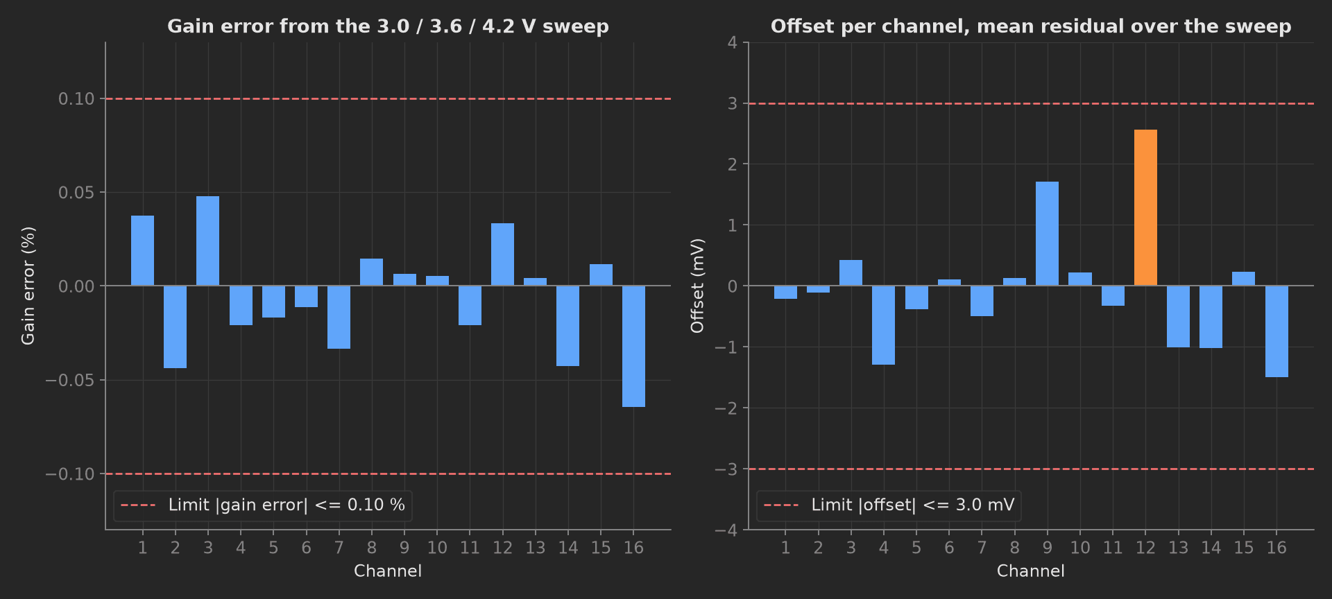
The sweep separates the two error terms: gain error is flat across the board (a wrong divider resistor on one input would stand out here), and the offset on channel 12 is the same 2 mV the staircase showed, now attributed to offset rather than gain.
Open Wire Check
One simulator channel is opened. The DUT must raise the open-wire fault for that channel; what it reads on the floating input is recorded but not limited, because it floats toward the neighbours' midpoint and looks plausible, which is the point. Once reconnected, the fault map is validated as one object against an all-empty expectation:
from utils.recipe import CELL_COUNT, IDLE_MV, OPEN_WIRE_CHANNELdef open_wire_check(measurements, bench, log): """Open one simulator channel and require the DUT to flag the wire, not report a plausible voltage. Then reconnect and require a clean fault map.""" bench.force_cells([IDLE_MV] * CELL_COUNT) bench.open_channel(OPEN_WIRE_CHANNEL) reported = bench.dut_read_cells_mv() faults = bench.dut_read_faults() flagged = OPEN_WIRE_CHANNEL in faults["open_wire"] log.info(f"Channel {OPEN_WIRE_CHANNEL} open: DUT reads {reported[OPEN_WIRE_CHANNEL - 1]:.1f} mV, " f"open-wire flags {faults['open_wire']}") measurements.open_wire_flagged = flagged measurements.open_wire_reading_mv = float(reported[OPEN_WIRE_CHANNEL - 1]) bench.close_channel(OPEN_WIRE_CHANNEL) measurements.faults_after_reconnect = bench.dut_read_faults()On the BQ76952 the open-wire check sources 22 to 95 µA into the input under test and can register as a transient OV or UV on that cell, so the phase runs after the accuracy phases and before the fault map is read again.
Tap Resistance
The one measurement in this template that is not in the usual BMS FCT list. The bleed path of each channel is switched on one at a time; on an external-balancing board the bleed current flows through the same harness wire, connector pin and solder joint the sense input hangs on. The voltage the AFE sees drops by I times R while the simulator's Kelvin readback at the fixture does not move, so the difference divided by the current the simulator sources on its 500 mA range is the series resistance of that tap path. It is the closest thing to a production test for a cold solder joint on a sense line, and it costs no extra instrument:
phases/tap_resistance.py24 lines
import numpy as npfrom utils.recipe import CELL_COUNT, IDLE_MVdef tap_resistance(measurements, bench, log): """Series resistance of every sense tap: bleed current through the tap path drops the voltage the AFE sees, the simulator's Kelvin sense does not move. R = dV / I_bleed, one channel at a time.""" bench.force_cells([IDLE_MV] * CELL_COUNT) idle = np.array(bench.dut_read_cells_mv()) r_mohm = np.zeros(CELL_COUNT) for ch in range(1, CELL_COUNT + 1): bench.dut_balance(ch, True) loaded = bench.dut_read_cells_mv()[ch - 1] i_ma = bench.sim_channel_current_ma(ch) bench.dut_balance(ch, False) r_mohm[ch - 1] = (idle[ch - 1] - loaded) / i_ma * 1000.0 measurements.tap_path.x_axis = list(range(1, CELL_COUNT + 1)) measurements.tap_path.y_axis.resistance = r_mohm.round(1).tolist() measurements.tap_path.y_axis.resistance.aggregations.max_mohm = float(r_mohm.max()) worst = int(r_mohm.argmax()) + 1 log.info(f"Tap resistance {r_mohm.min():.0f} .. {r_mohm.max():.0f} mOhm, worst channel {worst}")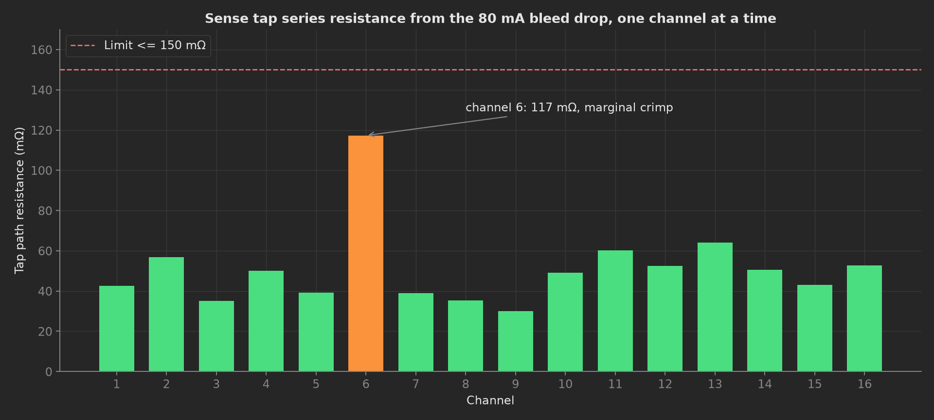
The mock's marginal crimp on channel 6: 117 mΩ against 30 to 65 mΩ on the other fifteen taps, still under the 150 mΩ limit, and exactly the kind of channel that passes every voltage test and shows up as a trend across a batch. Two conditions for the real bench: the AFE must convert while the bleed path is on (the LTC6811 family does this with the DCP bit; TI parts pause the ADC during balancing unless the cell-balance loop is slowed), and the board must be an external-balancing design, otherwise the bleed current flows through the input filter resistor and the drop is by design, not a defect.
Shutdown
The teardown phase commands ship mode, reads the stack's quiescent draw on the simulator's 250 µA range, and turns the outputs off. A stuck balancing FET or a wrong pull-up shows here as tens of milliamps against a limit of 250 µA:
from utils.recipe import CELL_COUNT, IDLE_MVdef shutdown(measurements, bench, log): """Teardown: ship mode, quiescent draw on the 250 uA range, outputs off. Runs after a failed main phase too, so no board is left balancing.""" bench.force_cells([IDLE_MV] * CELL_COUNT) bench.dut_ship_mode() ship_ua = bench.sim_total_current_ua() measurements.ship_current_ua = ship_ua log.info(f"Ship mode draw {ship_ua:.1f} uA across the stack") bench.outputs_off()Mock Plug
BmsBench stands in for both the simulator and the DUT's service port because the two have to share state (the DUT reads what the simulator forces) and plugs run in separate processes. Its config block in YAML becomes the constructor's cell_count and bleed_ma arguments. The mock draws a per-channel gain error with a 120 ppm standard deviation and an offset with a 0.6 mV standard deviation, both well inside the BQ79616 window, then sets channel 12 to +1.9 mV of offset and channel 6 to 115 mΩ of tap resistance so the charts have a story. Every method returns plain Python types, because plug calls cross a JSON boundary; a measurement read back from measurements.<key> returns a proxy, so the phases keep locals for their log lines.
On a real bench, split the class in two: the simulator over SCPI with pyvisa (SOUR:VOLT per channel, MEAS:VOLT and MEAS:CURR for the readback) and the DUT over pyserial or an I²C bridge. Keep the simulator's readback as the truth, run the accuracy phases with balancing off, and record the simulator model and calibration date in the run metadata, because a ±5 mV and a ±1 mV instrument produce numerically identical results that mean different things. The phases, measurements and limits stay the same.