
Get the complete source, dependencies and setup instructions from the template repository.
Open the source on GitHubIntroduction
Three-Axis Gimbal Overview
A drone's 3-axis gimbal uses three brushless motors (pitch, roll, yaw) under closed-loop control of an IMU mounted on the camera tray to keep the camera oriented in inertial space regardless of airframe motion. Stabilization error that reaches the camera shows up directly in the footage, as horizon tilt or rolling-shutter "jello" artifacts. Modern production gimbals achieve ±0.02° angular vibration range (DJI Ronin 2 spec) using encoder feedback on every motor and high-rate IMU fusion.
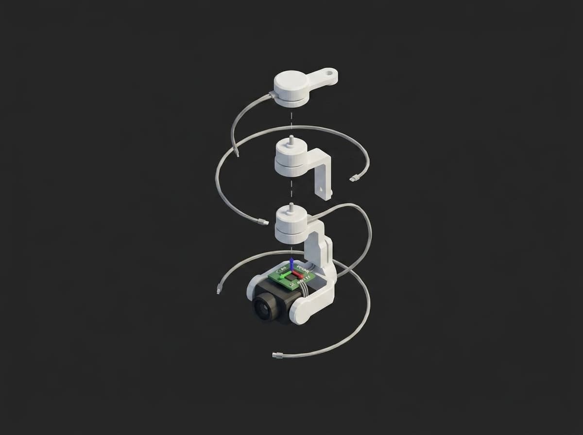
Yaw, roll and pitch motors stacked above the camera tray that carries the gimbal IMU.
The controller is typically a BaseCam SimpleBGC (AlexMos) 32-bit or a custom STM32-class board running a proprietary stack (DJI, Skydio, Freefly). Two IMUs are common: the camera-tray IMU (closed-loop control reference) and a frame IMU (drone attitude input for feed-forward). Both must be calibrated to the airframe so that the gimbal levels the camera against the actual horizon, not against a board-mounted reference rotated by manufacturing tolerance.
Calibration Purpose
Gimbal alignment calibration estimates:
- IMU-to-airframe rotation: the rotation between the gimbal IMU body frame and the drone airframe frame (level horizon, forward heading)
- Motor balance / payload center of mass: eliminates motor torque demand at zero rate so the gimbal can hold position with minimum current
- Stabilization accuracy: the residual horizon error under simulated airframe disturbance, judged against the product grade
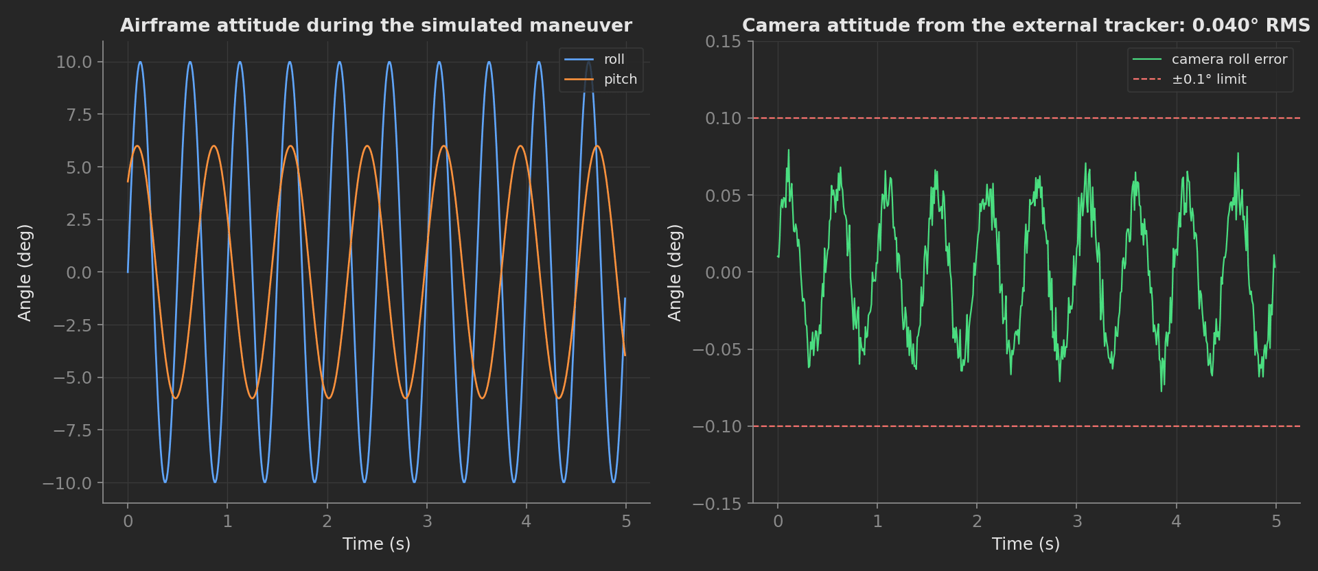
Airframe motion on the left, what the camera actually sees on the right: the residual is what the customer notices.
Per-unit calibration addresses a leading source of cinematic drone returns: horizon tilt (camera not level when drone is level) and mid-shot drift (slow horizon walk during a pan). Both look identical to the customer and both come from per-unit IMU mounting tolerance plus motor balance error.
Equipment & Setup
To implement gimbal calibration on a production line, the following are required:
- A level reference fixture: granite plate or precision tilt jig with sub-arc-minute leveling
- An external attitude reference: a precision tilt sensor or vision-based optical tracker
- A motion stage: robotic arm or air-bearing rotary table to apply known disturbances
- The Device Under Test (DUT): drone with gimbal and target camera/lens combo installed
- A TofuPilot Framework procedure to script the calibration, capture telemetry, fit calibration parameters, and validate metrics
- The TofuPilot Dashboard to store calibration parameters for traceability and production-stability trending
Hardware Components
Level Reference Fixture
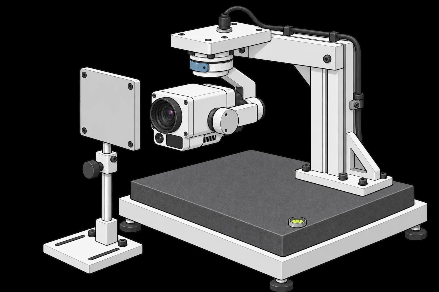
A granite surface plate (Grade AA or A, flatness within a few micrometres at bench sizes per ASME B89.3.7; Grade B runs roughly 5 µm at 300 mm) provides the production-grade level reference. The drone clamps to the plate via a non-magnetic fixture that holds the airframe flat and forward-facing. Magnetic fixtures interfere with the magnetometer in the airframe and gimbal IMU, so production uses aluminum or 3D-printed PETG/ABS fixtures.
The gimbal hangs from its mounting interface above the reference plate. The target faces the camera, with its plain back visible in this view.
External Attitude Reference
The gimbal's own IMU cannot validate itself. Production uses an external attitude reference: a tactical-grade MEMS IMU such as the Memsense MS-IMU3025 (0.6-0.8 °/h gyro bias instability), a Honeywell HG1700 ring-laser IMU (RLG tactical grade, overkill for most drones), or a vision-based optical tracker (OptiTrack PrimeX 41: 2048×2048, 180 FPS, ±0.10 mm 3D accuracy, with retro-reflective markers on the camera tray). The optical tracker is the preferred production choice because it has no mass and adds no perturbation to the gimbal.
For lower volume or development benches, a digital protractor (Wixey WR365, ±0.1°) suffices for static angle measurement but cannot capture dynamic response.
Disturbance Source
To validate stabilization accuracy, the airframe must be disturbed in a controlled way. Production benches use a 6-DOF Stewart platform or a robotic arm (a UR-series cobot such as the UR7e with a clamp end-effector) to drive sinusoidal roll, pitch, and yaw perturbations of ±10° at 0.5-5 Hz, matching typical flight disturbance spectra. For lower-cost lines, a manual rocking jig with a tach pickup is sufficient for go/no-go testing.
Custom Firmware
Both the drone autopilot and the gimbal controller must expose telemetry of their respective IMU outputs in raw form, plus the encoder positions for each gimbal motor. The procedure also requires a factory calibration mode that disables runtime offset compensation so the calibration sees the unfiltered sensor outputs. PX4 autopilots expose this via mavlink_send_param, BaseCam SimpleBGC via the SBGC32 Serial API. When writing calibration back to a SimpleBGC board, CMD_WRITE_PARAMS_3 saves to EEPROM; firmware 2.70+ recommends wrapping writes in CMD_WRITE_PARAMS_SET configuration mode, and the board resets about one second after the write, which the read-back verification must wait out.
Test Procedure
Overview
After clamping the DUT to the granite reference and connecting the external attitude tracker, the procedure runs:
- Mount Check: the operator confirms the mechanical preparation and selects the product grade.
- Rotation Fit: static gravity capture and IMU-to-airframe misalignment computation.
- Motor Balance: slow sweep per axis, current trace capture, DC offset extraction.
- Stabilization Test: disturbance rejection measured by the external tracker, judged against the grade the operator selected.
- Stream results to TofuPilot for traceability and analytics.
Total cycle ~3-5 minutes per DUT.
Why TofuPilot Framework?
TofuPilot Framework is a YAML + Python test framework built for hardware manufacturing. Instead of writing all your test logic, measurements, and limits inside Python code, you describe what the test does in a procedure.yaml file, and how in small Python phase files. The framework handles:
- Automatic Python environment management (via
uv) - Operator UI (no frontend code needed)
- Measurement validation and live charts
- Process isolation between phases and equipment plugs
This template additionally demonstrates the operator UI components (image reference, checklist, radio, textarea), operator input captured as measurements via bind, previous-results injection between phases, and run metadata.
Project Structure
You can find the full source on GitHub. The GimbalRig plug is a mock that simulates a slightly misaligned tray IMU and a mild pitch-axis imbalance, so the procedure runs end-to-end without hardware:
tofupilot run .For CI or bench automation, ui.json pre-bakes the operator inputs and the run executes headless:
tofupilot run . --no-tui --json --ui-values ui.json --ui-timeout 60The Procedure File
procedure.yaml declares the unit, the rig plug, and four phases. The first phase is the operator-facing one, and its ui.components block carries the whole interaction: a reference image, a checklist of balance steps, a radio for the product grade, and a textarea for free-form notes. Every input component is bound to a measurement, so the run report records what the operator actually confirmed:
procedure.yaml123 lines
name: Gimbal Three-Axis Alignment Calibrationversion: 0.1.0description: Calibrates gimbal IMU-to-airframe alignment, checks motor balance, and validates stabilization residual against a grade selected by the operator.plugs: - name: Gimbal Rig description: SBGC serial link plus external attitude reference. Mock simulates a slightly misaligned tray IMU and a mild pitch-axis imbalance. python: plugs.gimbal_rig:GimbalRig key: rigunit: auto_identify: true serial_number: default_value: "GMB-000042" part_number: default_value: "GIMBAL-3X-PRO"main: - name: Mount Check key: mount_check python: phases.mount_check measurements: - name: Balance Steps Done key: balance_steps_done - name: Grade Selected key: grade_selected validators: - operator: in expected_value: ["cinema", "fpv"] - name: Operator Notes key: operator_notes ui: components: - key: mounting_diagram type: image label: "Mounting Reference" description: "Clamp the airframe flat on the granite plate as shown" default_value: "./images/mounting.png" width: 50% - key: balance_steps type: checklist label: "Balance Adjustment Steps" description: "Complete every step before starting the capture" required: true bind: measurements.balance_steps_done options: - label: "Camera tray slid to neutral" value: "tray_neutral" - label: "Counterweight locked" value: "counterweight_locked" - label: "Cables routed slack across axes" value: "cables_slack" - key: grade type: radio label: "Product Grade" description: "Limits tighten for cinema-grade units" required: true bind: measurements.grade_selected options: - label: "Cinema (0.1° RMS)" value: "cinema" - label: "FPV (0.3° RMS)" value: "fpv" - key: notes type: textarea label: "Operator Notes" description: "Anything unusual about this unit" bind: measurements.operator_notes - name: Rotation Fit key: rotation_fit python: phases.rotation_fit depends_on: [mount_check] measurements: - name: Roll Misalignment key: roll_misalign_deg unit: deg validators: - {operator: ">=", expected_value: -1.5} - {operator: "<=", expected_value: 1.5} - name: Pitch Misalignment key: pitch_misalign_deg unit: deg validators: - {operator: ">=", expected_value: -1.5} - {operator: "<=", expected_value: 1.5} - name: Motor Balance key: motor_balance python: phases.motor_balance depends_on: [mount_check] measurements: - name: Pitch Current vs Angle key: pitch_current_curve title: Pitch Motor Current vs Angle description: Slow sweep through ±30°. A balanced axis is a zero-centered sinusoid; a DC offset is torque compensating a shifted center of mass. x_axis: legend: Angle unit: deg y_axis: - legend: Current key: current unit: mA - name: Pitch DC Offset key: pitch_dc_offset_ma unit: mA validators: - {operator: ">=", expected_value: -50.0} - {operator: "<=", expected_value: 50.0} - name: Stabilization Test key: stabilization python: phases.stabilization depends_on: [rotation_fit, motor_balance] measurements: - name: Stabilization Residual key: residual_rms_deg unit: deg - name: Within Grade Limit key: within_grade_limit validators: - operator: "==" expected_value: trueNote the shape of the dependency graph: rotation_fit and motor_balance both depend only on mount_check, so the framework runs them in parallel, and stabilization waits for both.
Mount Check Phase
The Python side of the operator phase is nearly empty. The UI components collect the inputs, bind writes them into measurements, and the grade_selected validator (in ["cinema", "fpv"]) enforces that a grade was chosen:
def mount_check(log, unit): """Operator phase: mounting diagram, balance checklist, grade radio, and free-form notes. Every input lands in a measurement via bind, so the run report keeps what the operator actually confirmed.""" log.info(f"Preparing gimbal {unit.serial_number} for calibration")The image component sources ./images/mounting.png relative to the procedure directory. The checklist value arrives as the array of checked option values, the radio as the selected value string. balance_steps_done and operator_notes declare no validators, so they record with an UNSET outcome: stored and queryable in the report, but never affecting pass/fail.
Rotation Fit
With the airframe level on the granite plate, a perfectly mounted tray IMU reads gravity as [0, 0, -g]. Roll and pitch misalignment fall directly out of the measured vector components:
import numpy as npdef rotation_fit(measurements, rig, log): """Fit the tray-IMU-to-airframe rotation from the static gravity vector. With the airframe level on the granite plate, a perfectly mounted IMU reads [0, 0, -g]. Roll and pitch misalignment fall directly out of the measured vector components.""" v = np.array(rig.static_gravity_capture(5, 200)) g = np.linalg.norm(v) pitch = float(np.degrees(np.arcsin(-v[0] / g))) roll = float(np.degrees(np.arcsin(v[1] / (g * np.cos(np.radians(pitch)))))) measurements.roll_misalign_deg = roll measurements.pitch_misalign_deg = pitch log.info(f"Misalignment roll {roll:+.2f} deg, pitch {pitch:+.2f} deg")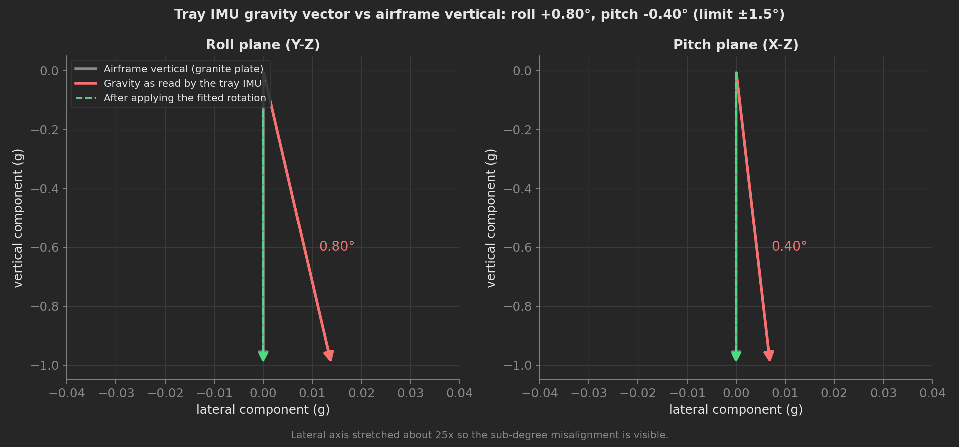
The mock rig's tray IMU sits 0.80° off in roll and -0.40° in pitch; the fit recovers both to two decimals.
Motor Balance
A well-balanced gimbal draws zero motor current at rest because gravity passes through the rotational axis. Production tolerance, lens swaps, and accessory mounts shift the COM by millimeters and the motor must work to compensate, wasting battery and limiting peak slew rate.
The phase sweeps the pitch axis through ±30° while logging motor current. A balanced axis shows a sinusoidal current vs angle pattern centered on zero; an unbalanced axis shows a constant DC offset proportional to torque demand. The full trace lands in a multi-dimensional measurement, rendered by the dashboard as an interactive chart, and the DC offset is validated numerically:
import numpy as npdef motor_balance(measurements, rig, log): """Sweep the pitch axis through ±30° and split the current trace into its sinusoidal gravity term and the DC offset that indicates a shifted center of mass.""" sweep = rig.sweep_axis("pitch", 30, 61) current = np.array(sweep["current_ma"]) measurements.pitch_current_curve.x_axis = sweep["angles_deg"] measurements.pitch_current_curve.y_axis.current = sweep["current_ma"] dc_offset = float(current.mean()) measurements.pitch_dc_offset_ma = dc_offset log.info(f"Pitch DC offset {dc_offset:+.1f} mA")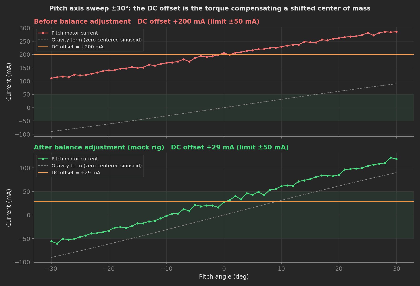
Same sweep before and after the operator's balance adjustment; only the DC offset moves.
Stabilization Test
The disturbance source drives the airframe through a sinusoidal pattern while the external tracker records how far the camera tray strays from level. The pass limit depends on the grade the operator picked in Mount Check, read here through previous-results injection: naming a parameter after a completed phase's key injects that phase's measurements and outcome. The phase reads two upstream phases this way, taking the grade from mount_check and logging the misalignment the rotation_fit phase measured, then stamps the grade and the operator notes onto the run metadata, so the dashboard can filter runs by either:
phases/stabilization.py29 lines
import numpy as npGRADE_LIMITS_DEG = {"cinema": 0.1, "fpv": 0.3}def stabilization(measurements, rig, log, run, mount_check, rotation_fit): """Disturb the airframe and measure how far the camera tray strays from level. The pass limit comes from the grade the operator selected in the Mount Check phase, read here through previous-results injection.""" grade = str(mount_check.grade_selected) limit = GRADE_LIMITS_DEG[grade] log.info(f"Grade {grade}: residual limit {limit} deg RMS") roll = float(rotation_fit.roll_misalign_deg) pitch = float(rotation_fit.pitch_misalign_deg) log.info( f"Rotation fit {rotation_fit.outcome}: compensating " f"roll {roll:+.2f} deg, pitch {pitch:+.2f} deg" ) capture = rig.disturbance_capture(2.0, 10.0, 5.0) residual = np.array(capture["camera_deg"]) rms = float(np.sqrt(np.mean(residual**2))) measurements.residual_rms_deg = rms measurements.within_grade_limit = rms <= limit run.metadata["grade"] = grade run.metadata["operator_notes"] = str(mount_check.operator_notes) log.info(f"Residual {rms:.3f} deg RMS")The targets (< 0.1° RMS cinema, < 0.3° RMS FPV) are internal production limits, not industry standards; set them from your golden-unit data. Because the limit is grade-dependent, the boolean within_grade_limit measurement carries the pass/fail decision while residual_rms_deg keeps the raw value trendable across both grades.
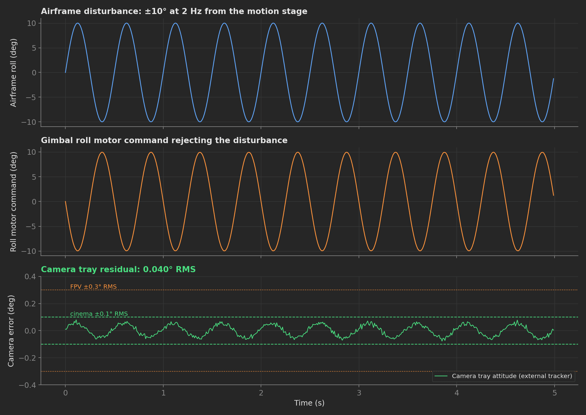
Disturbance in, motor command out, and the camera residual the tracker measures: 0.040° RMS, inside the cinema grade.
Mock Rig Plug
The GimbalRig plug simulates the SBGC serial link and the external attitude reference: a tray IMU mounted 0.8° off in roll and -0.4° in pitch, a pitch axis with a mild center-of-mass offset, and a disturbance-rejection loop with cinema-grade residual. Swap the class for one speaking the SBGC32 Serial API and your OptiTrack NatNet stream; the phases stay unchanged.