
Get the complete source, dependencies and setup instructions from the template repository.
Open the source on GitHubIntroduction
Programming and Serialization Overview
MCU programming and serialization is the last point in PCBA manufacturing where the device is open for write access before functional test. Three operations sequence in this stage: firmware flash, per-unit data write (serial number, MAC address, calibration constants, keys), and verify-readback. It is frequently merged into the FCT station to save a fixture and one handling step, but logically separable: programming uses debug-port access whereas FCT exercises the running firmware. Many high-mix EMS lines keep them distinct so a programming failure does not block FCT throughput.
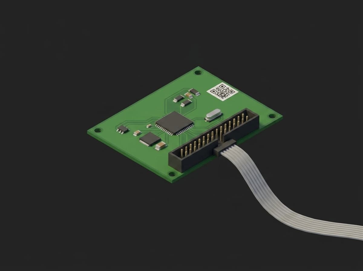
The board as the station sees it: the data-matrix serial the operator scans, the 10-pin SWD header the fixture probes, the MCU that leaves this station with an identity it keeps for life.
The output: every shipped board carries a unique identity (serial, MAC, BLE address), a production-validated firmware image (CRC-verified against the release file), and per-unit calibration constants (ADC offset and gain trim, RTC trim, sensor offsets). This identity stays with the unit through its lifetime, indexed in MES and TofuPilot.
Test Purpose
The programming and serialization procedure produces a per-board record of:
- Target identity: SW-DP IDCODE, device ID, flash size, so a wrong-variant MCU placed at SMT is rejected before anything is written
- Allocated MAC address from an IEEE-registered block, plus the pool level
- Firmware flash through the vendor programmer CLI, with its transcript attached to the run
- Identity page with serial, MAC and calibration block, recorded as JSON
- Flash CRC computed by the target against the CRC of the release image, firmware version, readback of the identity
- Read-out protection level after lock, and the rail state after teardown
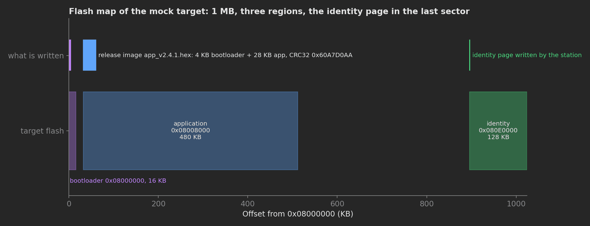
The mock target's flash: the release image covers the start of the bootloader and application regions, the station writes the identity page in the last sector, and the CRC check covers the image the programmer wrote.
Per-unit programming eliminates mis-flashed firmware revision, missing bootloader, duplicate serial number, blank identity page, MAC pool exhaustion, and unlocked production units. Every shipped board is traceable from the production database to the customer.
Beyond the programming content, this template demonstrates five framework mechanics: an executable phase that runs the programmer CLI and passes on its exit code, string, boolean and JSON measurements next to the numeric ones, a station-scoped plug for the MES connection, unit metadata written from Python, and a file attachment of the programmer transcript on the run.
Equipment & Setup
To implement programming and serialization on a production line, the following are required:
- A programming tool (single or gang) matched to the target MCU family
- A test fixture with the SWD / JTAG header on pogo pins and a switched 3.3 V rail
- A barcode scanner for the board serial and a label printer for the shipping label
- MES integration for MAC allocation, calibration lookup and result recording
- The Device Under Test (DUT): an ICT-passed PCBA with an un-programmed MCU
- A TofuPilot Framework procedure to orchestrate probe, allocate, flash, write, verify and lock
- The TofuPilot Dashboard to log per-board programming history
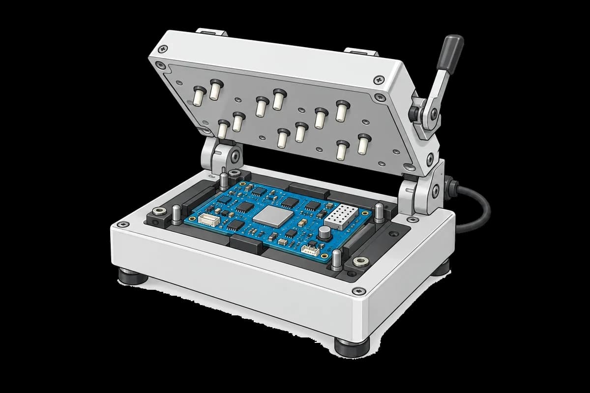
The board is located in a clamshell contact fixture. The programmer, barcode scanner, label printer and test computer are not shown.
Hardware Components
Programming Tool
Selection depends on volume and MCU family:
- STMicroelectronics ST-LINK V3 with STM32CubeProgrammer: SWD / JTAG plus a UART / I2C / SPI / CAN bridge to exercise the system bootloader from the same fixture. Its
STM32_Programmer_CLIis the command this template's executable phase stands in for. - SEGGER J-Link family: J-Link Plus / Pro for engineering and low volume, Flasher Compact for medium volume, Flasher ATE and Flasher Hub for gang programming, all scriptable from the test station over USB or Ethernet.
- Microchip MPLAB PICkit 5 / ICD with MPLAB IPE for PIC / dsPIC; Nordic nrfjprog and pyOCD for Nordic and generic Cortex-M targets.
- Automated programmers (BPM Microsystems, Data I/O) sit upstream of SMT to pre-program memories and MCUs on tape or tray before placement; the end-of-line station then only writes identity and verifies.
Protocols
- SWD (ARM 2-wire, pin-compatible subset of JTAG): default for Cortex-M
- JTAG (IEEE 1149.1): boundary scan plus in-system programming for higher-pin-count parts and FPGAs
- System bootloader in ROM (STM32: UART, SPI, I2C, USB-DFU, CAN depending on family), when the debug port is not accessible in the fixture
- I2C / SPI EEPROM: direct write to a side memory holding MAC and serial
- USB-DFU: when the device's USB port is the only test-accessible interface
Identity Sources
The serial number comes from the data-matrix already on the board (scanned at identification). The MAC address comes from an IEEE-registered block (an MA-L, MA-M or MA-S assignment under the company's OUI) handed out by MES one address per request, so two stations never write the same one. Calibration constants come from upstream test phases keyed by serial. The firmware image is built per release with a fixed layout: bootloader, application, and a reserved identity page the station fills.
Test Procedure
Overview
After the board is loaded into the fixture and its data-matrix scanned, the procedure runs:
- Power the 3.3 V rail, check idle current, read the SW-DP IDCODE, device ID and flash size.
- Ask MES for a MAC address, record the pool level, stamp the MAC on the unit metadata.
- Flash the release image through the programmer CLI (executable phase).
- Write the identity page: serial, MAC, calibration block.
- Read back the flash CRC and compare it with the CRC of the release image, read the firmware version, check the identity readback, attach the programmer transcript.
- Set read-out protection level 1 and confirm the debug port is locked.
- Teardown: rail off before the operator opens the fixture.
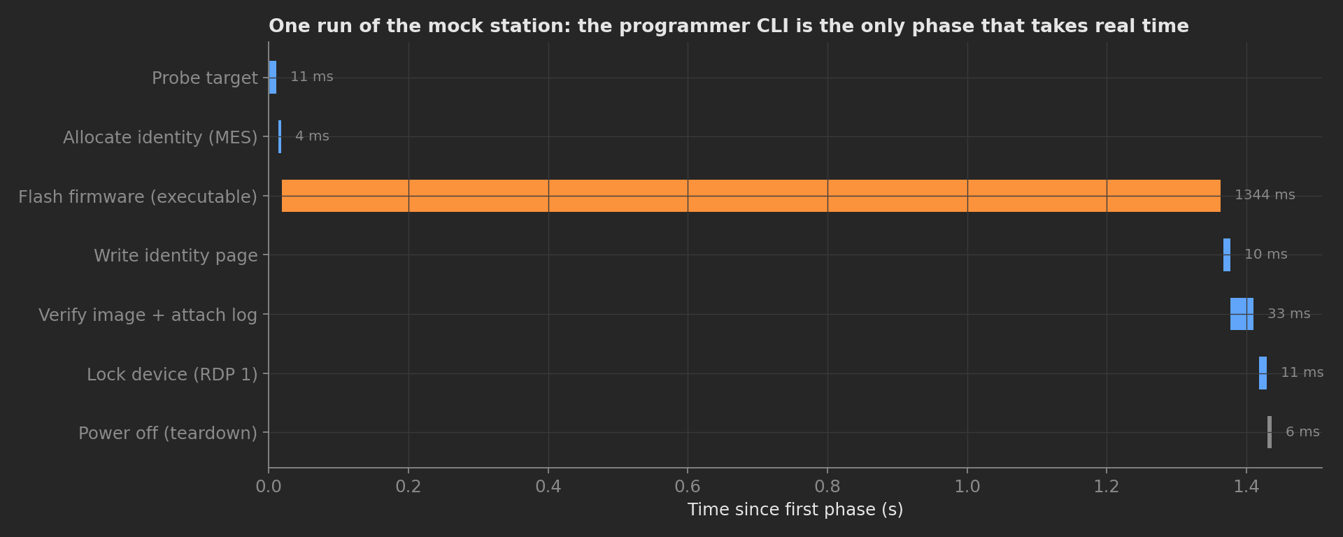
One run of the mock station as recorded by the CLI: the programmer transcript is the only phase that takes real time, everything around it is bookkeeping the framework records.
Why TofuPilot Framework?
TofuPilot Framework is a YAML + Python test framework built for hardware manufacturing. Instead of writing all your test logic, measurements, and limits inside Python code, you describe what the test does in a procedure.yaml file, and how in small Python phase files. The framework handles:
- Automatic Python environment management (via
uv) - Operator UI (no frontend code needed)
- Measurement validation and live charts
- Process isolation between phases and equipment plugs
Project Structure
The plugs are mocks and the programmer CLI is a shell script that prints a CubeProgrammer-style transcript, so the procedure runs green on any machine. The firmware file is a real 32 KB Intel HEX image whose CRC32 is the value the verify phase expects. Run it with tofupilot run . --no-tui --no-kiosk --json. You can find the full source on GitHub.
The Procedure File
This is the exact file the template ships, verified end to end with the CLI:
procedure.yaml150 lines
name: MCU Programming and Serializationversion: 0.1.0description: Flashes the release firmware over SWD, allocates the unit identity from MES, writes the identity page, verifies the image CRC, and locks the debug port.unit: auto_identify: true serial_number: description: "Scan the data-matrix on the board" placeholder: "UAUT-00000" pattern: "^UAUT-\\d{5}$" default_value: "UAUT-04829" part_number: default_value: "PCB-MAIN-V2" metadata: mac_address: description: "Allocated by MES during the run" firmware_version: description: "Read back from the target after flashing"plugs: - name: Fixture Power description: 3.3 V rail through the pogo pins (mock) python: plugs.psu:FixturePower key: power - name: SWD Probe description: Debug probe on the 10-pin header (mock ST-LINK / J-Link) python: plugs.swd:SwdProbe key: swd - name: MES Identity Service description: MAC pool and calibration lookup, connection held across units python: plugs.mes:IdentityService key: mes scope: stationmain: - name: Probe Target key: probe_target python: phases.probe_target measurements: - name: Rail Voltage key: rail_voltage unit: V validators: - {operator: ">=", expected_value: 3.2} - {operator: "<=", expected_value: 3.4} - name: Idle Current key: idle_current unit: mA description: Unprogrammed target in reset. A short on the rail shows up here before any flash access. validators: - {operator: "<=", expected_value: 80.0} - name: SW-DP IDCODE key: idcode validators: - {operator: "==", expected_value: "0x2BA01477"} - name: Device ID key: device_id description: Rejects a wrong-variant MCU placed at SMT before anything is written. validators: - {operator: in, expected_value: ["0x413", "0x419"]} - name: Flash Size key: flash_size unit: KB validators: - {operator: "==", expected_value: 1024} - name: Allocate Identity key: allocate_identity python: phases.allocate_identity depends_on: [probe_target] measurements: - name: MAC Address key: mac_address validators: - {operator: matches, expected_value: "^70:B3:D5:[0-9A-F]{2}:[0-9A-F]{2}:[0-9A-F]{2}$"} - name: MAC Pool Remaining key: pool_remaining description: Addresses left in the OUI block; reorder below 500. validators: - {operator: ">=", expected_value: 500} - name: Flash Firmware key: flash_firmware depends_on: [allocate_identity] timeout: 120s executable: command: "sh tools/mock_flash.sh firmware/app_v2.4.1.hex" # Real bench: STM32_Programmer_CLI -c port=SWD mode=UR -d firmware/app_v2.4.1.hex -v - name: Write Identity key: write_identity python: phases.write_identity depends_on: [flash_firmware] measurements: - name: Identity Page Address key: identity_address validators: - {operator: "==", expected_value: "0x080E0000"} - name: Calibration Block key: calibration_block description: Per-unit constants written next to the identity, recorded as JSON for later comparison. - name: Verify Image key: verify_image python: phases.verify_image depends_on: [write_identity] measurements: - name: Flash CRC key: flash_crc description: CRC32 the target computes over its flash, compared to the CRC of the release image. validators: - {operator: "==", expected_value: "0x60A7D0AA"} - name: Firmware Version key: firmware_version validators: - {operator: in, expected_value: ["2.4.1"]} - name: Verify Mismatch Bytes key: verify_mismatch_bytes unit: B validators: - {operator: "==", expected_value: 0} - name: Identity Readback key: identity_readback validators: - {operator: "==", expected_value: true} - name: Lock Device key: lock_device python: phases.lock_device depends_on: [verify_image] measurements: - name: RDP Level key: rdp_level validators: - {operator: "==", expected_value: 1} - name: Debug Locked key: debug_locked validators: - {operator: "==", expected_value: true}teardown: - name: Power Off key: power_off python: phases.power_off measurements: - name: Rail Off Voltage key: rail_off_voltage unit: V validators: - {operator: "<=", expected_value: 0.1}Framework features to notice:
- Executable phase:
flash_firmwarehas no Python. The framework runs the command through the shell from the procedure directory, passes the phase on exit code 0 and fails it otherwise; thetimeoutbounds a programmer that hangs on a dead target. Swapping the mock script forSTM32_Programmer_CLI,JLinkExeornrfjprogis a one-line change. - String measurements:
idcodevalidates with==,device_idwithin(two accepted variants),mac_addresswith amatchesregex pinned to the company's OUI,flash_crcandfirmware_versionwith==andin. - Boolean and JSON measurements:
identity_readbackanddebug_lockedare booleans validated== true;calibration_blockis a JSON measurement with no validator, recorded for trending. - Station-scoped plug:
scope: stationkeeps the MES connection alive across units in station mode, so back-to-back boards do not pay the reconnection; in a one-shottofupilot runit behaves as a normal per-execution plug. - Unit metadata from Python:
mac_addressandfirmware_versionare declared underunit.metadataand filled by the phases, so the dashboard unit carries both and can be filtered by either.
Probe Target
The first phase powers the rail and reads what is on the other end of the SWD header. The SW-DP IDCODE identifies the debug port (0x2BA01477 is the ARM Cortex-M4 SW-DP), the device ID identifies the silicon (0x413 is STM32F405/407), and the flash size confirms the variant. Together they reject a wrong part before the programmer writes a byte:
def probe_target(measurements, power, swd, log): power.enable(3.3) measurements.rail_voltage = power.measure_rail() measurements.idle_current = power.measure_current_ma() idcode = swd.read_idcode() device_id = swd.read_device_id() flash_kb = swd.flash_size_kb() log.info(f"Target {device_id} IDCODE {idcode}, {flash_kb} KB flash") measurements.idcode = idcode measurements.device_id = device_id measurements.flash_size = flash_kbAllocate Identity
MES hands out the next MAC in the company's block and reports how many are left. The phase records both and stamps the MAC on the unit metadata:
def allocate_identity(measurements, mes, unit, log): identity = mes.allocate(unit.serial_number) log.info(f"Allocated MAC {identity['mac']} for {unit.serial_number}") measurements.mac_address = identity["mac"] measurements.pool_remaining = mes.pool_remaining() unit.metadata["mac_address"] = identity["mac"]Flash Firmware
The executable phase runs the programmer. On the real bench the command is the vendor CLI; the template ships a shell script that prints the same kind of transcript, writes it to flash.log for the verify phase to attach, and exits 0:
text24 lines
------------------------------------------------------------------- Mock Programmer CLI v2.19.0 -------------------------------------------------------------------ST-LINK SN : 0670FF3234424E3043212637Voltage : 3.29VSWD freq : 4000 KHzConnect mode: Under resetDevice ID : 0x413Device name : STM32F405xx/F407xx/F415xx/F417xxFlash size : 1 MBytesMemory Programming ... File : firmware/app_v2.4.1.hex Size : 32768 Bytes Address : 0x08000000Erasing memory corresponding to segment 0: Erasing internal memory sectors [0 1]Download in Progress: 10% ... 100%File download completeTime elapsed during download operation: 00:00:01.240Verifying ...Download verified successfullyA non-zero exit from the programmer fails the phase, the dependent phases are skipped, and the teardown still powers the fixture down.
Write Identity
The identity page holds the serial, the MAC just allocated, and the calibration constants MES keeps for this serial. The MAC comes from the previous phase through previous-results injection: naming a parameter after a completed phase's key injects its measurements:
def write_identity(measurements, swd, mes, unit, allocate_identity, log): calibration = mes.calibration_for(unit.serial_number) block = {"serial": unit.serial_number, "mac": allocate_identity.mac_address, **calibration} address = swd.write_identity(block) log.info(f"Identity page written at 0x{address:08X}") measurements.identity_address = f"0x{address:08X}" measurements.calibration_block = calibrationAssigning a dict to a measurement stores it as JSON, so the exact constants written to this board are on its run without flattening them into separate fields.
Verify Image
The CRC the target computes over its flash is compared with the CRC32 of the release file, computed on the station from the Intel HEX. The firmware version is read back, the identity page is compared with what was allocated, the firmware version lands on the unit metadata, and the programmer transcript is attached to the run:
from utils.intel_hex import image_crc32FIRMWARE = "firmware/app_v2.4.1.hex"def verify_image(measurements, swd, unit, attach, allocate_identity, log): expected = image_crc32(FIRMWARE) actual = swd.read_flash_crc() version = swd.read_firmware_version() log.info(f"Flash CRC {actual}, release image {expected}, firmware {version}") measurements.flash_crc = actual measurements.firmware_version = version measurements.verify_mismatch_bytes = swd.verify_mismatch_bytes() measurements.identity_readback = swd.read_identity().get("mac") == allocate_identity.mac_address unit.metadata["firmware_version"] = version attach.file("flash.log", f"{unit.serial_number}_flash.log")Two details worth knowing: a measurement read back from measurements.<key> returns a proxy, so keep the value in a local variable when you also write it to unit.metadata (metadata accepts strings, numbers and booleans only); and attach.file takes an optional second argument to name the attachment, here prefixed with the serial so the transcript is findable from the unit page.
The release image CRC is a plain utility over the HEX records:
utils/intel_hex.py23 lines
import zlibdef read_hex(path): ext = 0 chunks = [] with open(path) as fh: for line in fh: line = line.strip() if not line.startswith(":"): continue raw = bytes.fromhex(line[1:]) count, addr, rtype, data = raw[0], (raw[1] << 8) | raw[2], raw[3], raw[4:-1] if rtype == 0x04: ext = ((data[0] << 8) | data[1]) << 16 elif rtype == 0x00: chunks.append((ext + addr, data)) chunks.sort(key=lambda c: c[0]) return b"".join(d for _, d in chunks)def image_crc32(path): return f"0x{zlib.crc32(read_hex(path)) & 0xFFFFFFFF:08X}"Lock Device
After verification passes, read-out protection goes to level 1: the debug port is blocked, the flash cannot be read back, and the setting is reversible with a mass erase. Level 2 is permanent and belongs behind an explicit sign-off, which is why the template stops at 1:
def lock_device(measurements, swd, log): swd.set_rdp(1) level = swd.read_rdp() log.info(f"Read-out protection level {level}") measurements.rdp_level = level measurements.debug_locked = level >= 1Mock Plugs
The SWD mock returns the identifiers of an STM32F405, keeps the identity page it was given so the readback check has something to compare, and computes the "target" CRC from the same release file. The MES mock hands out sequential MACs from a fixed block and returns a fixed calibration block. Both carry the method surface a real pylink or MES client needs to implement:
plugs/mes.py21 lines
class IdentityService: OUI = "70:B3:D5" # example IEEE MA-M style prefix POOL_SIZE = 4096 def __init__(self): self._next = 0x1A2B00 self._used = 0 print("MES identity service connected") def allocate(self, serial_number): mac = f"{self.OUI}:{(self._next >> 16) & 0xFF:02X}:{(self._next >> 8) & 0xFF:02X}:{self._next & 0xFF:02X}" self._next += 1 self._used += 1 return {"serial": serial_number, "mac": mac, "ble_addr": mac} def pool_remaining(self): return self.POOL_SIZE - self._used def calibration_for(self, serial_number): """Constants measured upstream (ADC trim, RTC trim) keyed by serial.""" return {"adc_offset_lsb": 8, "adc_gain": 1.012, "rtc_trim_ppm": -3.5}On a real bench, point the flash_firmware command at the programmer CLI, replace plugs/swd.py with a pylink or pyOCD implementation, and plugs/mes.py with the MES client; the phases, measurements, and limits stay exactly the same.