
Get the complete source, dependencies and setup instructions from the template repository.
Open the source on GitHubIntroduction
400G DR4 Transceiver Overview
A 400GBASE-DR4 transceiver carries 400 Gb/s over four parallel single-mode fibres at 1310 nm, 106.25 Gb/s PAM4 on each, for up to 500 m between a switch and the next tier of a data center fabric. In the QSFP-DD form factor the host side is eight electrical lanes of 53.125 Gb/s PAM4 (400GAUI-8) that a DSP gearboxes to the four optical lanes; the optical side is a silicon-photonics chip with four Mach-Zehnder modulators fed by one or two 1310 nm lasers, four germanium photodiodes, and an MPO-12 port that uses eight of its twelve fibres. One module that ships out of spec is not one dead link: it is a link that runs at a pre-FEC error rate the switch's RS(544,514) decoder cannot hold when the fibre plant adds its own loss, a lane that drops out at the top of the switch's temperature range, or a module whose power class lies to the host and pushes a 32-port line card over its cage budget.
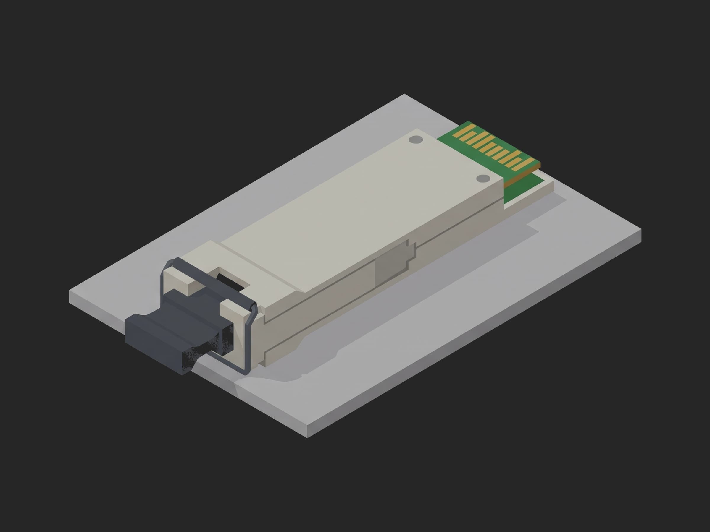
The parts this test exercises: the CMIS management interface behind the gold edge contacts, the laser and modulator bias loops that set the launch power and the eye, the receiver photodiodes and the DSP's equaliser, the thermal path from the case to the laser TEC, and the MPO port that every result in the transmitter table is measured through.
IEEE 802.3 Clause 124 specifies the physical layer as two tables at two test points. At TP2, the end of a short patch cord on the transmitter, Table 124-6 gives average launch power -2.9 to +4.0 dBm, OMAouter -0.8 to +4.2 dBm, extinction ratio at least 3.5 dB, TDECQ at most 3.4 dB, and OMAouter minus TDECQ at least -2.2 dBm, each per lane. TDECQ, the transmitter and dispersion eye closure for PAM4, is measured with the SSPRQ pattern through a fourth-order Bessel-Thomson reference receiver at 13.28 GHz and a five-tap feed-forward reference equaliser, so it is a number the scope computes, not one the operator reads off an eye. At TP3, the receiver, Table 124-7 gives sensitivity as the OMAouter at which the BER reaches 2.4e-4, the rate the FEC corrects, with the limit max(-3.9 dBm, SECQ - 5.3 dB) where SECQ is the eye closure of the reference transmitter used for the test, a stressed receiver sensitivity of -1.9 dBm with a conformance signal closed to 3.4 dB of SECQ, an average receive power range of -5.9 to +4 dBm and a damage threshold of 5 dBm. A vendor datasheet such as the FS 400G QSFP-DD DR4 SiPh restates those rows unchanged. The QSFP-DD MSA hardware specification rev 7.0 adds the mechanical envelope, the 0 to 70 C commercial case range and the power classes, class 6 being at most 12 W. Every limit in this template is one of those rows, or says where it came from instead.
Test Purpose
The procedure records one end-of-line fingerprint per module:
- CMIS identity as one object, the reported serial against the scanned label, the date code, the power class and the module power against the class ceiling, and the temperature after two minutes in high-power mode
- The MPO connection checked lane by lane on the power meter, with a dark fibre raising an error that the procedure retries after the operator cleans the ferrule
- The TP2 transmitter table per lane: average launch power, OMAouter, extinction ratio and TDECQ as four curves on one lane axis, each judged on its Clause 124 window, with the raw eye summary attached to the run
- Receiver sensitivity per lane by attenuator sweep from the reference transmitter until the BER crosses 2.4e-4, the whole BER curve kept for the worst lane, and the reference transmitter's SECQ and calibration id recorded so the -3.9 dBm limit is traceable
- Stressed receiver sensitivity: BER per lane with the conformance eye at -1.9 dBm
- TDECQ and launch power at the 0 and 70 C case corners, judged on the same windows and on their shift from the 25 C values injected from the earlier phase
- The user EEPROM stamped with the station and date at teardown, read back, and the module parked in low-power mode
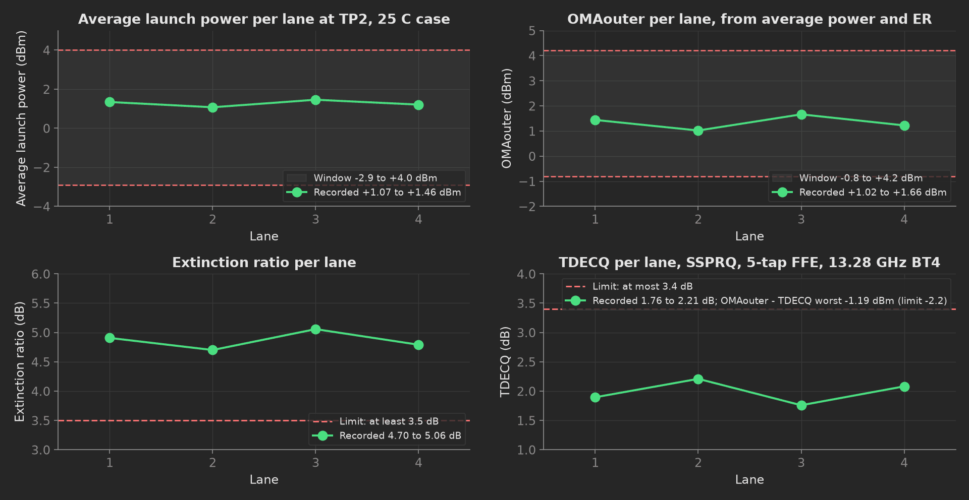
The mock module's transmitter table against Clause 124: four lanes inside every window, the worst lane at 2.21 dB of TDECQ against a 3.4 dB limit and at -1.19 dBm of OMAouter minus TDECQ against -2.2 dBm.
The framework mechanics on show are then: {error: retry} with a retry limit and delay on the MPO connection, so the common false fail of a dirty ferrule costs a cleaning and not a module; previous-results injection, the temperature phase naming tx_optical as a parameter to get the 25 C curves it compares against; attach.data for the raw eye summary; run.metadata for the reference transmitter and its calibration record; unit.metadata written at teardown next to an EEPROM read-back; and multi-dimensional measurements with the lane as x-axis and a different aggregation set on each curve.
Equipment & Setup
To run this test on a production line, the following are required:
- A host evaluation board with a QSFP-DD cage, a CMIS management port over I2C, and a current monitor on the 3.3 V rail
- A case clamp with a thermoelectric element holding the module case at 0, 25 and 70 C
- An MPO-12 APC to LC fan-out on a 1x4 optical switch, so one scope channel and one attenuator serve all four lanes
- A sampling oscilloscope with an optical reference receiver at 13.28 GHz and the PAM4 TDECQ analysis
- A calibrated reference transmitter with a stressed-eye path for the SRS conformance signal, driven by a BERT that generates PRBS13Q and SSPRQ and counts errors
- A variable optical attenuator and an optical power meter
- The Device Under Test (DUT): a 400GBASE-DR4 QSFP-DD module with its production firmware
- A TofuPilot Framework procedure to sequence the stimuli and validate the limits
- The TofuPilot Dashboard to keep the per-module evidence, the BER curves and the eye summaries
Hardware Components
Sampling Scope, BERT and Reference Transmitter
The transmitter table is a scope measurement: a Keysight N1092A DCA-M with the 400G PAM4 analysis option applies the 13.28 GHz Bessel-Thomson response and the five-tap FFE and reports TDECQ, OMAouter, ER and the average power per capture, triggered by the module's own SSPRQ pattern. The receiver side needs a reference transmitter whose eye is known: a Keysight M8040A BERT drives it with PRBS13Q, adds the sinusoidal jitter and interference that close the eye to the 3.4 dB SECQ of the conformance signal for the stressed test, and counts the errored bits behind the module's receiver through the host board. An EXFO FVA-600 attenuator sets the received OMAouter in 0.25 dB steps and a Keysight N7744C power meter reads the four lanes through the fan-out; the switch in front of the fan-out selects the lane for the scope and the attenuator.
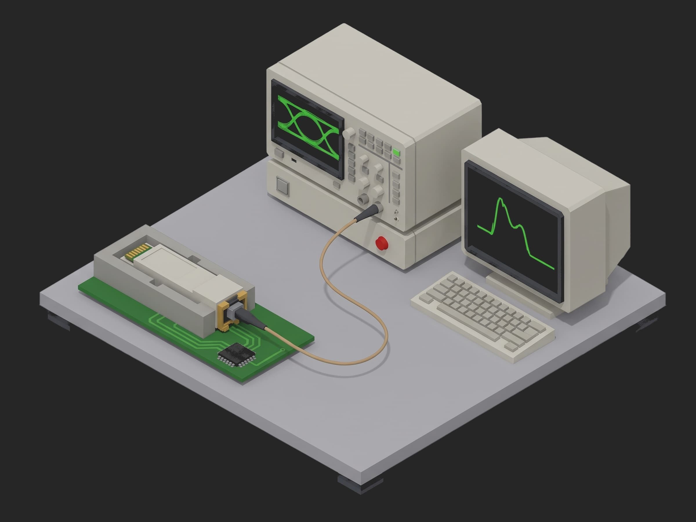
A single-socket station: the module in the host board's cage under the case clamp, the MPO fan-out to the switch, the scope and the attenuator stacked beside it, the BERT and the reference transmitter inside the rack.
Host Board and MPO Connection
The host board is where CMIS lives: page 00h for the identity, the power class in byte 200, the LowPwr control and the module state, page 03h for the user EEPROM the teardown writes. The MPO-12 APC connection is the one part of the station the operator touches on every module, and a single contaminated fibre end face is the common false fail on an optical line: the lane reads dark or several dB low, the module is good, and the fix is a fibre inspection scope and a cleaner. IEC 61300-3-35 gives the inspection criteria (scratches and defects by zone on the end face); the procedure raises on a dark lane and retries after the operator has inspected and cleaned, rather than recording a failed module.
Where the Limits Come From
| Test | Limit | Basis |
|---|---|---|
| Identity, serial, date code | exact match, label match, YYMMDD | CMIS page 00h; no tolerance applies |
| Power class, module power | class 6, ≤ 12 W | QSFP-DD MSA rev 7.0 power classes |
| Module temperature | ≤ 60 °C after 2 min in a 25 °C cage | this line's derivation: a module hotter here reaches the 70 °C case ceiling in the customer's switch |
| MPO lane power | min ≥ -2.9 dBm, spread ≤ 1.0 dB, dark below -10 dBm raises | -2.9 dBm is the Clause 124 launch minimum; the spread and the dark threshold are this line's |
| Average launch power | -2.9 to +4.0 dBm per lane | Clause 124 Table 124-6 |
| OMAouter | -0.8 to +4.2 dBm per lane | Table 124-6 |
| Extinction ratio | ≥ 3.5 dB per lane | Table 124-6 |
| TDECQ | ≤ 3.4 dB per lane, SSPRQ, 13.28 GHz BT4, 5-tap FFE | Table 124-6 and 124-8 |
| OMAouter - TDECQ | ≥ -2.2 dBm, worst lane | Table 124-6 |
| Receiver sensitivity | ≤ -3.9 dBm OMAouter at BER 2.4e-4, worst lane | Table 124-7: max(-3.9 dBm, SECQ - 5.3 dB); the reference Tx SECQ is required ≤ 1.4 dB so the -3.9 dBm term governs |
| Stressed receiver sensitivity | BER ≤ 2.4e-4 on every lane at -1.9 dBm with 3.4 dB SECQ | Table 124-7 |
| Receiver power ceiling | ≤ 4 dBm presented during the sweep | Table 124-7 average receive power maximum; damage at 5 dBm |
| Temperature corners | TDECQ ≤ 3.4 dB and launch power in window at 0 and 70 °C; shift from 25 °C ≤ 0.6 dB TDECQ, ≤ 0.5 dB power | windows from Clause 124, case range from the MSA; the deltas are this line's derivation, sized to catch a bias or TEC loop that has lost its lock |
| EEPROM stamp, module state | exact | no tolerance applies |
Two rows in that table are traps. The TP2 table applies at the end of the patch cord, so the fan-out and the switch are inside the measurement: their loss has to be calibrated out per lane, or the station fails good modules on launch power by the 0.5 dB it eats. And the sensitivity limit depends on the bench: max(-3.9, SECQ - 5.3) is -3.9 dBm only while the reference transmitter's SECQ is at most 1.4 dB, which is why the phase records that SECQ from the calibration record and validates it, and why the calibration id goes into the run metadata. Two stations with different reference transmitters otherwise disagree on the same module.
Test Procedure
Overview
The procedure maps the test onto the framework's three stages. Identity and power live in setup: so the module's class and draw are known before the transmitter is enabled. The MPO connection opens main: with a retry, and the four optical phases chain on one switch and one attenuator. The EEPROM stamp and the park live in teardown: so the module goes to low-power mode even when a main phase fails.
- Setup: CMIS identity, serial against the label, power class, module power and temperature after 2 min.
- Main: transmitter on, four lane powers on the meter; a dark fibre raises and the phase retries.
- Main: TP2 per lane on the scope, launch power, OMAouter, ER, TDECQ; eye summary attached.
- Main: attenuator sweep per lane to BER 2.4e-4, curve kept for the worst lane, reference Tx recorded.
- Main: stressed conformance eye at -1.9 dBm, BER per lane.
- Main: case clamp at 0 and 70 C, TDECQ and launch power against the injected 25 C values.
- Teardown: station and date into the user EEPROM, read back, transmitter off, low-power mode.
Every metric validates against limits declared in procedure.yaml, and results stream to TofuPilot as the per-module evidence.
Why TofuPilot Framework?
TofuPilot Framework is a YAML + Python test framework built for hardware manufacturing. Instead of writing all your test logic, measurements, and limits inside Python code, you describe what the test does in a procedure.yaml file, and how in small Python phase files. The framework handles:
- Automatic Python environment management (via
uv) - Operator UI (no frontend code needed)
- Measurement validation and live charts
- Process isolation between phases and equipment plugs
Project Structure
You can find the full source on GitHub. The Dr4Bench plug is a mock of the host board, the case clamp, the switch and fan-out, the scope, the reference transmitter, the attenuator, the power meter and the BERT together, synthesizing a healthy module with about 1.3 dBm per lane, 4.9 dB of ER and 2 dB of TDECQ, a receiver reaching the FEC threshold near -5.6 dBm, and one contaminated fibre on the first MPO read, so the procedure runs end-to-end without a bench or a module connected.
tofupilot run .For CI or bench automation, the same run executes headless:
tofupilot run . --no-tui --no-kiosk --jsonThe Procedure File
procedure.yaml declares the unit, the bench plug with the label serial as constructor argument, and the three stages with every measurement and limit:
procedure.yaml317 lines
name: 400G DR4 Transceiver TP2 Testversion: 0.1.0description: End-of-line test of a 400GBASE-DR4 QSFP-DD silicon-photonics transceiver against IEEE 802.3 Clause 124. CMIS identity and power class, the MPO connection checked lane by lane with a retry for a dirty ferrule, the TP2 transmitter table per lane (average launch, OMAouter, ER, TDECQ) on the sampling scope, receiver sensitivity by attenuator sweep to the 2.4e-4 FEC threshold with the BER curve kept for the worst lane, stressed receiver sensitivity at -1.9 dBm, TDECQ and launch power at the 0 and 70 C case corners against the 25 C values, and a teardown that stamps the station and date into the user EEPROM and parks the module in low-power mode.unit: auto_identify: true serial_number: description: "Scan the data-matrix on the module's pull tab" placeholder: "QDD-DR4-000000" pattern: "^QDD-DR4-\\d{6}$" default_value: "QDD-DR4-004417" part_number: default_value: "QDD-400G-DR4-S" batch_number: default_value: "LOT-2026-38"plugs: - name: DR4 Bench description: "Host board with CMIS port, case clamp, MPO fan-out and switch, sampling scope, reference transmitter, attenuator, power meter and BERT (mock, one plug per bench)" python: plugs.dr4_bench:Dr4Bench key: bench config: serial_number: "QDD-DR4-004417"setup: - name: Identify and Power key: identify_and_power python: phases.identify_and_power timeout: 5m measurements: - name: Module Identity key: module_identity description: "CMIS page 00h vendor, part, hardware revision, firmware and media as one object against the release." validators: - operator: "==" expected_value: vendor: TP-PHOTONICS part: QDD-400G-DR4-S hw_rev: B2 firmware: 2.1.4 media: SiPh 1310 nm MPO-12 APC - name: Reported Serial key: reported_serial validators: - {operator: matches, expected_value: "^QDD-DR4-\\d{6}$"} - name: Serial Matches Label key: serial_matches_label description: "The serial the module reports over CMIS is the one on its pull tab." validators: - {operator: "==", expected_value: true} - name: Date Code key: date_code description: "CMIS date code, YYMMDD." validators: - {operator: matches, expected_value: "^2\\d{5}$"} - name: Power Class key: power_class description: "QSFP-DD MSA rev 7.0 power class from page 00h byte 200; class 6 is the 12 W the host cage is budgeted for." validators: - {operator: "==", expected_value: 6} - name: Module Power key: module_power_w unit: W description: "Host 3.3 V rail current times voltage in high-power mode after the warm-up; the class 6 ceiling." validators: - {operator: "<=", expected_value: 12.0} - name: Module Temperature key: module_temperature_c unit: °C description: "Internal monitor after 2 min in high-power mode in a 25 C host cage. 60 C is this line's derivation; a module hotter here reaches the 70 C case ceiling in the customer's switch." validators: - {operator: "<=", expected_value: 60.0}main: - name: MPO Connect key: mpo_connect python: phases.mpo_connect retry: limit: 2 delay: 2s then: error: retry measurements: - name: MPO Lane Power key: mpo_lane_power title: Average power per lane at TP2 on the power meter after the cord is seated x_axis: legend: Lane y_axis: - legend: Average power key: avg_power_dbm unit: dBm aggregations: - type: min_dbm unit: dBm validators: - {operator: ">=", expected_value: -2.9} - type: spread_db unit: dB validators: - {operator: "<=", expected_value: 1.0} - name: Tx Optical key: tx_optical python: phases.tx_optical depends_on: [mpo_connect] measurements: - name: Transmitter at TP2 key: tx_optical title: Average launch power, OMAouter, ER and TDECQ per lane at 25 C case x_axis: legend: Lane y_axis: - legend: Average launch power key: avg_power_dbm unit: dBm aggregations: - type: min_dbm unit: dBm validators: - {operator: ">=", expected_value: -2.9} - type: max_dbm unit: dBm validators: - {operator: "<=", expected_value: 4.0} - legend: OMAouter key: oma_outer_dbm unit: dBm aggregations: - type: min_dbm unit: dBm validators: - {operator: ">=", expected_value: -0.8} - type: max_dbm unit: dBm validators: - {operator: "<=", expected_value: 4.2} - legend: Extinction ratio key: er_db unit: dB aggregations: - type: min_db unit: dB validators: - {operator: ">=", expected_value: 3.5} - legend: TDECQ key: tdecq_db unit: dB aggregations: - type: max_db unit: dB validators: - {operator: "<=", expected_value: 3.4} - type: min_oma_minus_tdecq_dbm unit: dBm validators: - {operator: ">=", expected_value: -2.2} - name: Rx Sensitivity key: rx_sensitivity python: phases.rx_sensitivity depends_on: [tx_optical] measurements: - name: BER Curve key: ber_curve title: BER against received OMAouter for the worst lane, reference transmitter through the attenuator x_axis: legend: Received OMAouter unit: dBm y_axis: - legend: BER key: ber aggregations: - type: sensitivity_dbm unit: dBm validators: - {operator: "<=", expected_value: -3.9} - name: Rx Sensitivity key: rx_sensitivity title: Receiver sensitivity per lane, OMAouter at BER 2.4e-4 x_axis: legend: Lane y_axis: - legend: Sensitivity key: sensitivity_dbm unit: dBm aggregations: - type: max_dbm unit: dBm validators: - {operator: "<=", expected_value: -3.9} - name: Reference Tx SECQ key: reference_tx_secq_db unit: dB description: "Eye closure of the bench's reference transmitter from its calibration record. Clause 124 sets the sensitivity limit at max(-3.9 dBm, SECQ - 5.3 dB); at 1.4 dB or better the -3.9 dBm term governs." validators: - {operator: "<=", expected_value: 1.4} - name: Rx Power Ceiling key: rx_power_ceiling_dbm unit: dBm description: "Highest OMAouter the sweep presents to the receiver. The operating maximum is 4 dBm and the damage threshold 5 dBm." validators: - {operator: "<=", expected_value: 4.0} - name: Stressed Rx key: stressed_rx python: phases.stressed_rx depends_on: [rx_sensitivity] measurements: - name: Stressed Rx BER key: stressed_rx_ber title: BER per lane with the stressed conformance signal at -1.9 dBm OMAouter x_axis: legend: Lane y_axis: - legend: BER key: ber aggregations: - type: max_ber validators: - {operator: "<=", expected_value: 0.00024} - name: SRS Bits per Lane key: srs_bits_per_lane unit: bit description: "Gate of 10 s per lane at 106.25 Gb/s; enough errors at the threshold to count, not to estimate." validators: - {operator: ">=", expected_value: 1000000000000} - name: All Lanes Under FEC Threshold key: all_lanes_under_fec_threshold validators: - {operator: "==", expected_value: true} - name: Temperature Corners key: temperature_corners python: phases.temperature_corners depends_on: [stressed_rx] timeout: 40m measurements: - name: Temperature Corners key: temperature_corners title: TDECQ and average launch power per lane at the 0 and 70 C case corners x_axis: legend: Lane y_axis: - legend: TDECQ at 0 C key: tdecq_0c unit: dB aggregations: - type: max_db unit: dB validators: - {operator: "<=", expected_value: 3.4} - legend: TDECQ at 70 C key: tdecq_70c unit: dB aggregations: - type: max_db unit: dB validators: - {operator: "<=", expected_value: 3.4} - legend: Average launch power at 0 C key: avg_power_0c unit: dBm aggregations: - type: min_dbm unit: dBm validators: - {operator: ">=", expected_value: -2.9} - type: max_dbm unit: dBm validators: - {operator: "<=", expected_value: 4.0} - legend: Average launch power at 70 C key: avg_power_70c unit: dBm aggregations: - type: min_dbm unit: dBm validators: - {operator: ">=", expected_value: -2.9} - type: max_dbm unit: dBm validators: - {operator: "<=", expected_value: 4.0} - name: Max TDECQ Delta key: max_tdecq_delta_db unit: dB description: "Largest change in TDECQ on any lane at either corner against the 25 C value from tx_optical. 0.6 dB is this line's derivation; a modulator bias loop that has lost its lock moves more." validators: - {operator: "<=", expected_value: 0.6} - name: Max Power Delta key: max_power_delta_db unit: dB description: "Largest change in average launch power on any lane at either corner against 25 C. 0.5 dB is this line's derivation; a laser TEC loop that has lost its lock moves more." validators: - {operator: "<=", expected_value: 0.5}teardown: - name: Park and EEPROM key: park_and_eeprom python: phases.park_and_eeprom measurements: - name: EEPROM Stamp key: eeprom_stamp description: "Station id and test date written to the CMIS user EEPROM page 03h." validators: - {operator: matches, expected_value: "^OPT-EOL-\\d{2} \\d{4}-\\d{2}-\\d{2}$"} - name: EEPROM Readback Matches key: eeprom_readback_matches description: "The page reads back what was written." validators: - {operator: "==", expected_value: true} - name: Module State key: module_state description: "CMIS module state after the host asserts LowPwr, so the module is cold when the operator pulls it." validators: - {operator: "==", expected_value: LowPwr}Framework features to notice:
then: {error: retry}with aretrylimit and delay.mpo_connectraises on a dark lane; the framework waits two seconds, runs the phase again, up to two retries, and the run continues with the retried attempt. Every attempt is kept and shown on the run. On a real line auiprompt in front of the retry tells the operator what to clean.- Previous-results injection.
temperature_cornersnamestx_opticalas a function parameter and receives that phase's results, the 25 C curves included, to compute its deltas;depends_onguarantees the order. attach.datafor the raw file. The PAM4 level means, the equaliser taps and the wavelength per lane travel with the run astp2_eye_summary.json, so a TDECQ that drifts across a lot can be traced to a level or a tap.run.metadatafor the bench's identity. The reference transmitter and its calibration id are on the run, not on the unit: a sensitivity drift across a week can be split between modules and reference.unit.metadataand an EEPROM read-back. The teardown writes the station and date into the module and onto the unit record, and a boolean says the module holds what was written.- Four curves on one lane axis, each with its own aggregations.
tx_opticalcarries launch power, OMAouter, ER and TDECQ against the lane; the windows aremin_dbmandmax_dbm, the floormin_db, the ceilingmax_db, and the combined rulemin_oma_minus_tdecq_dbm. - A whole curve judged on one interpolated number.
ber_curvekeeps the sweep of the worst lane and validatessensitivity_dbm.
Identify and Power
CMIS page 00h the moment the module is seated: the identity as one object against the release, the serial against the label, the date code, and the power class. Then the host releases low-power mode and the module settles for two minutes before the 3.3 V rail current and the internal temperature are read. The mock skips the two minutes; the timeout is sized for the real ones.
phases/identify_and_power.py27 lines
from utils.recipe import POWER_CLASS_LIMIT_W, WARM_UP_MINdef identify_and_power(measurements, bench, unit, log): """Setup: CMIS page 00h read the moment the module is seated, then the host releases low-power mode and the module settles for two minutes before its power and temperature are read. A module that reports the wrong power class is a switch that oversubscribes its cage budget.""" identity = bench.cmis_identity() serial = bench.cmis_serial() date_code = bench.cmis_date_code() power_class = bench.cmis_power_class() bench.set_low_power(False) bench.warm_up(WARM_UP_MIN) log.info(f"Warm-up: {WARM_UP_MIN} min in high-power mode (mock: instant)") power_w = bench.host_module_power_w() temp_c = bench.cmis_temperature_c() measurements.module_identity = identity measurements.reported_serial = serial measurements.serial_matches_label = serial == unit.serial_number measurements.date_code = date_code measurements.power_class = power_class measurements.module_power_w = power_w measurements.module_temperature_c = temp_c unit.metadata["firmware"] = identity["firmware"] unit.metadata["date_code"] = date_code log.info(f"{identity['vendor']} {identity['part']} rev {identity['hw_rev']} fw {identity['firmware']} reports {serial} ({date_code}), label {unit.serial_number}; class {power_class} ({POWER_CLASS_LIMIT_W[power_class]:.0f} W), draws {power_w:.2f} W, {temp_c:.1f} C after {WARM_UP_MIN} min")MPO Connect
The transmitter is enabled and the four lanes are read on the power meter through the fan-out. A lane below -10 dBm is dark: the cord is not seated, is keyed wrong, or has a contaminated end face on that fibre. The phase raises, and the procedure's then: {error: retry} runs it again after the operator has inspected and cleaned the ferrule per IEC 61300-3-35. Once all four lanes carry light, the phase records them and judges the lane-to-lane spread: four fibres of one clean MPO agree within a few tenths of a dB, and a single dirty end face shows as one lane a decibel low.
phases/mpo_connect.py22 lines
from utils.recipe import LANES, LIGHT_PRESENT_DBMdef mpo_connect(measurements, bench, log): """Setup: transmitter on, the four TP2 powers read on the power meter through the MPO fan-out. A dark fibre means the cord is not seated, is keyed wrong, or has a contaminated end face on that fibre: the phase raises, the operator inspects and cleans the ferrule (IEC 61300-3-35) and reseats, and the procedure's `then: error: retry` runs the phase again. A dirty connector does not fail the module.""" bench.tx_enable(True) powers = bench.meter_lane_powers_dbm() dark = [lane for lane, p in zip(LANES, powers) if p < LIGHT_PRESENT_DBM] if dark: raise RuntimeError(f"Lane {dark} dark at the power meter ({powers} dBm): inspect the MPO end face per IEC 61300-3-35, clean, reseat and retry") spread = max(powers) - min(powers) m = measurements.mpo_lane_power m.x_axis = LANES m.y_axis.avg_power_dbm = powers m.y_axis.avg_power_dbm.aggregations.min_dbm = round(min(powers), 2) m.y_axis.avg_power_dbm.aggregations.spread_db = round(spread, 2) log.info(f"MPO seated: {powers} dBm at TP2 on the meter, lane spread {spread:.2f} dB")The mock's first read shows lane 3 at -31.4 dBm; the retried attempt reads +1.34, +0.96, +1.43 and +1.18 dBm with a 0.47 dB spread.
Tx Optical
Four captures on the sampling scope at 25 C case, one per lane through the switch: average launch power, OMAouter, extinction ratio and TDECQ with the SSPRQ pattern, the 13.28 GHz reference receiver and the five-tap FFE. The four series go on one lane axis; each carries the aggregations Clause 124 judges it on, and the TDECQ series also carries the worst OMAouter minus TDECQ. The level means, the taps and the wavelength are attached as one JSON file.
phases/tx_optical.py40 lines
import jsonfrom utils.recipe import LANES, TX_FFE_TAPS, TX_PATTERN, TX_SCOPE_BW_GHZdef tx_optical(measurements, bench, attach, log): """TP2 at 25 C case on the sampling scope: average launch power, OMAouter, ER and TDECQ per lane with the SSPRQ pattern, the 13.28 GHz Bessel-Thomson reference receiver and the 5-tap FFE of Clause 124. The raw eye summary (PAM4 level means, equaliser taps, wavelength) travels with the run as an attachment.""" bench.set_case_temp_c(25.0) avg, oma, er, tdecq, raw = [], [], [], [], {} for lane in LANES: r = bench.scope_tx_lane(lane) avg.append(r["avg_dbm"]) oma.append(r["oma_dbm"]) er.append(r["er_db"]) tdecq.append(r["tdecq_db"]) raw[f"lane_{lane}"] = r log.info(f"Lane {lane}: {r['avg_dbm']:+.2f} dBm avg, OMAouter {r['oma_dbm']:+.2f} dBm, ER {r['er_db']:.2f} dB, TDECQ {r['tdecq_db']:.2f} dB at {r['wavelength_nm']:.1f} nm") oma_minus_tdecq = [o - t for o, t in zip(oma, tdecq)] m = measurements.tx_optical m.x_axis = LANES m.y_axis.avg_power_dbm = avg m.y_axis.avg_power_dbm.aggregations.min_dbm = round(min(avg), 3) m.y_axis.avg_power_dbm.aggregations.max_dbm = round(max(avg), 3) m.y_axis.oma_outer_dbm = oma m.y_axis.oma_outer_dbm.aggregations.min_dbm = round(min(oma), 3) m.y_axis.oma_outer_dbm.aggregations.max_dbm = round(max(oma), 3) m.y_axis.er_db = er m.y_axis.er_db.aggregations.min_db = round(min(er), 3) m.y_axis.tdecq_db = tdecq m.y_axis.tdecq_db.aggregations.max_db = round(max(tdecq), 3) m.y_axis.tdecq_db.aggregations.min_oma_minus_tdecq_dbm = round(min(oma_minus_tdecq), 3) raw["conditions"] = {"pattern": TX_PATTERN, "reference_receiver_ghz": TX_SCOPE_BW_GHZ, "ffe_taps": TX_FFE_TAPS, "case_c": 25.0} attach.data(json.dumps(raw, indent=2).encode(), "tp2_eye_summary.json") log.info(f"Worst lane: TDECQ {max(tdecq):.2f} dB, OMAouter - TDECQ {min(oma_minus_tdecq):+.2f} dBm, ER {min(er):.2f} dB")OMAouter follows from the average power and the ER: OMA = 2 P (ER - 1) / (ER + 1) in linear units, so at 4.9 dB of ER it sits 0.1 dB above the average power. The OMAouter minus TDECQ rule is the one to watch on a silicon-photonics transmitter: a modulator biased off quadrature keeps its OMA and loses its eye, and fails this row before it fails TDECQ alone.
Rx Sensitivity
Each lane's receiver against the reference transmitter through the attenuator: from -2 dBm down in 0.25 dB steps with one second of gating per step until the BER crosses 2.4e-4, then the sensitivity interpolated in log10(BER) between the last two steps. The whole curve is kept for the worst lane; every lane records its sensitivity. The reference transmitter's SECQ from its calibration record is validated at 1.4 dB or better, the condition under which the fixed -3.9 dBm term of the Clause 124 limit governs, and the calibration id goes into the run metadata.
phases/rx_sensitivity.py59 lines
import mathimport numpy as npfrom utils.recipe import BER_THRESHOLD, LANES, SWEEP_GATE_S, SWEEP_START_DBM, SWEEP_STEP_DB, SWEEP_STOP_DBMdef sweep_lane(bench, lane): """Attenuator down in 0.25 dB steps from -2 dBm until the BER crosses the FEC threshold; the sensitivity is interpolated in log10(BER) between the last two steps. Returns the sweep floor if the lane never crossed.""" powers, bers = [], [] p = SWEEP_START_DBM while p >= SWEEP_STOP_DBM: bench.set_rx_oma_dbm(lane, p) errors, bits = bench.ber_gate(lane, SWEEP_GATE_S) powers.append(p) bers.append(errors / bits) if bers[-1] > BER_THRESHOLD: break p = round(p - SWEEP_STEP_DB, 2) if bers[-1] <= BER_THRESHOLD: return powers, bers, SWEEP_STOP_DBM lb = [math.log10(max(b, 1e-15)) for b in bers[-2:]] frac = (math.log10(BER_THRESHOLD) - lb[0]) / (lb[1] - lb[0]) return powers, bers, round(powers[-2] + frac * (powers[-1] - powers[-2]), 3)def rx_sensitivity(measurements, bench, run, log): """Each lane's receiver against the calibrated reference transmitter through the attenuator, one second of gating per step. The whole BER curve is kept for the worst lane; every lane records its sensitivity. The Clause 124 limit is max(-3.9 dBm, SECQ - 5.3 dB) where SECQ is the reference transmitter's own eye closure; with a reference at 1.4 dB or better the -3.9 dBm term governs, so the reference's SECQ is recorded.""" ref = bench.reference_tx() run.metadata["reference_tx"] = ref["id"] run.metadata["reference_tx_cal"] = ref["cal_id"] bench.srs_enable(False) curves, sens = {}, [] for lane in LANES: powers, bers, s = sweep_lane(bench, lane) curves[lane] = (powers, bers) sens.append(s) log.info(f"Lane {lane}: {len(powers)} steps of {SWEEP_GATE_S:.0f} s (mock: instant), BER {bers[-1]:.2e} at {powers[-1]:+.2f} dBm, sensitivity {s:+.2f} dBm") worst = LANES[int(np.argmax(sens))] powers, bers = curves[worst] m = measurements.ber_curve m.x_axis = powers[::-1] m.y_axis.ber = bers[::-1] m.y_axis.ber.aggregations.sensitivity_dbm = sens[worst - 1] s = measurements.rx_sensitivity s.x_axis = LANES s.y_axis.sensitivity_dbm = sens s.y_axis.sensitivity_dbm.aggregations.max_dbm = round(max(sens), 3) measurements.reference_tx_secq_db = ref["secq_db"] measurements.rx_power_ceiling_dbm = SWEEP_START_DBM log.info(f"Worst lane {worst} at {max(sens):+.2f} dBm OMA; reference {ref['id']} ({ref['cal_id']}, SECQ {ref['secq_db']} dB)")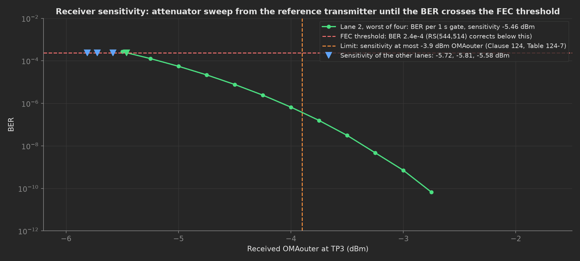
The mock module's worst lane reaches the FEC threshold at -5.46 dBm, 1.56 dB below the limit; the other three at -5.72, -5.81 and -5.58 dBm. The waterfall is the receiver's Gaussian tail: a decade of BER for about 0.6 dB of optical power near the threshold, which is why the sweep steps at 0.25 dB and why a limit at -3.9 dBm with a module at -5.5 dBm is a comfortable margin and a module at -4.2 dBm is not.
Stressed Rx
The conformance signal, the reference eye closed to 3.4 dB of SECQ, at -1.9 dBm OMAouter on each lane for ten seconds. Every lane must stay under the FEC threshold. The stress is what the reference equaliser cannot recover; a receiver whose DSP recovers most of it reads a BER well under the limit, one that does not reads at it.
phases/stressed_rx.py25 lines
from utils.recipe import BER_THRESHOLD, LANES, SRS_GATE_S, SRS_OMA_DBM, SRS_SECQ_DBdef stressed_rx(measurements, bench, log): """Stressed receiver sensitivity: the conformance signal with 3.4 dB of SECQ at -1.9 dBm OMAouter, ten seconds of gating per lane. Every lane must stay under the FEC threshold; the DSP has to recover the eye that the reference equaliser cannot.""" bench.srs_enable(True) bers = [] bits = 0 for lane in LANES: bench.set_rx_oma_dbm(lane, SRS_OMA_DBM) errors, bits = bench.ber_gate(lane, SRS_GATE_S) bers.append(errors / bits) log.info(f"Lane {lane}: {errors} errors in {bits:.3e} bits at {SRS_OMA_DBM} dBm with {SRS_SECQ_DB} dB SECQ, BER {bers[-1]:.2e} (gate {SRS_GATE_S:.0f} s, mock: instant)") bench.srs_enable(False) m = measurements.stressed_rx_ber m.x_axis = LANES m.y_axis.ber = bers m.y_axis.ber.aggregations.max_ber = max(bers) measurements.srs_bits_per_lane = float(bits) measurements.all_lanes_under_fec_threshold = max(bers) <= BER_THRESHOLD log.info(f"Worst stressed lane BER {max(bers):.2e}, a factor {BER_THRESHOLD / max(bers):.1f} under the {BER_THRESHOLD:.1e} threshold")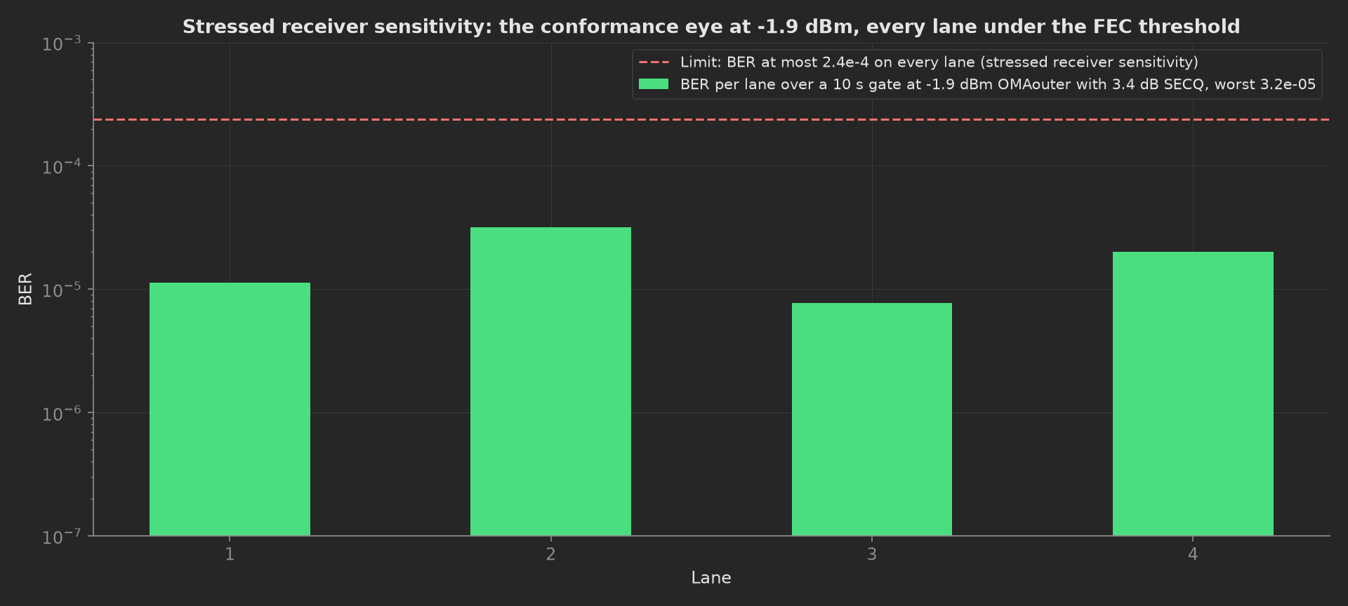
The mock module's stressed BER per lane: 1.1e-5, 3.2e-5, 7.7e-6 and 2.0e-5, the worst a factor 7.5 under the threshold. A factor of ten on BER near the threshold is about half a decibel of optical margin, so the bars are read on a log scale and a lane an order of magnitude above its siblings is a lane to look at even when it passes.
Temperature Corners
The case clamp goes to 0 C, soaks, and the four lanes are captured again on the scope; then 70 C. TDECQ and launch power at each corner are judged on the same Clause 124 windows, and lane by lane against the 25 C values the tx_optical phase recorded, injected here as a parameter. The mock skips the soaks; the timeout is sized for two real ones.
phases/temperature_corners.py50 lines
from utils.recipe import CASE_TEMPS_C, LANES, SOAK_MINdef curve(result, key): """One y-axis series out of the injected multi-dimensional measurement.""" return [float(v) for v in next(y for y in result["y_axis"] if y["key"] == key)["data"]]def temperature_corners(measurements, bench, tx_optical, log): """TDECQ and average launch power re-measured at the 0 and 70 C case corners after a soak at each, and compared lane by lane with the 25 C values the tx_optical phase recorded, injected here by phase key. A laser TEC loop or a modulator bias loop that has lost its lock shows up as a delta long before it fails an absolute limit.""" base = tx_optical.tx_optical base_tdecq = curve(base, "tdecq_db") base_avg = curve(base, "avg_power_dbm") corners = {} for temp in CASE_TEMPS_C: bench.set_case_temp_c(temp) bench.soak(SOAK_MIN) log.info(f"Case clamp at {temp:.0f} C, soak {SOAK_MIN} min (mock: instant)") tdecq, avg = [], [] for lane in LANES: r = bench.scope_tx_lane(lane) tdecq.append(r["tdecq_db"]) avg.append(r["avg_dbm"]) corners[temp] = (tdecq, avg) log.info(f"{temp:.0f} C: TDECQ {tdecq} dB, avg {avg} dBm") bench.set_case_temp_c(25.0) t0, a0 = corners[0.0] t70, a70 = corners[70.0] d_tdecq = [t - b for t, b in zip(t0 + t70, base_tdecq + base_tdecq)] d_avg = [a - b for a, b in zip(a0 + a70, base_avg + base_avg)] m = measurements.temperature_corners m.x_axis = LANES m.y_axis.tdecq_0c = t0 m.y_axis.tdecq_0c.aggregations.max_db = round(max(t0), 3) m.y_axis.tdecq_70c = t70 m.y_axis.tdecq_70c.aggregations.max_db = round(max(t70), 3) m.y_axis.avg_power_0c = a0 m.y_axis.avg_power_0c.aggregations.min_dbm = round(min(a0), 3) m.y_axis.avg_power_0c.aggregations.max_dbm = round(max(a0), 3) m.y_axis.avg_power_70c = a70 m.y_axis.avg_power_70c.aggregations.min_dbm = round(min(a70), 3) m.y_axis.avg_power_70c.aggregations.max_dbm = round(max(a70), 3) measurements.max_tdecq_delta_db = round(max(abs(d) for d in d_tdecq), 3) measurements.max_power_delta_db = round(max(abs(d) for d in d_avg), 3) log.info(f"Largest shift from 25 C: TDECQ {max(d_tdecq, key=abs):+.2f} dB, launch power {max(d_avg, key=abs):+.2f} dB")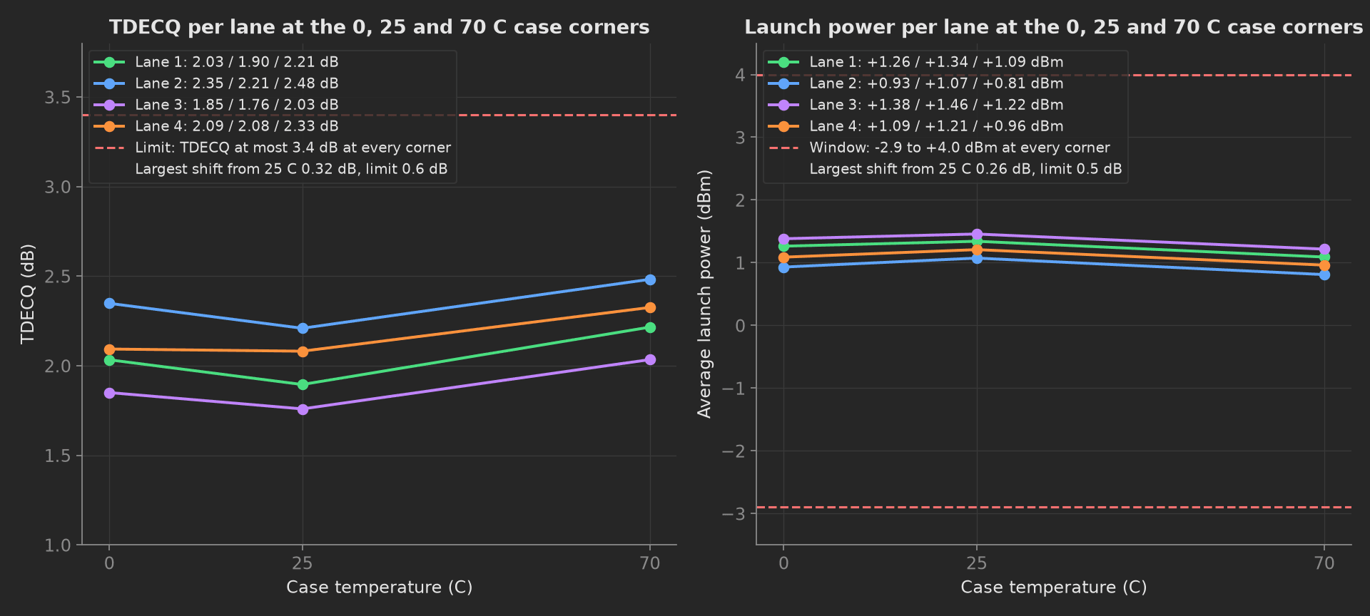
The mock module drifts the way a healthy silicon-photonics transmitter does: TDECQ up 0.31 dB and launch power down 0.24 dB at 70 C, with the lanes moving together. The delta limits are not in Clause 124; they are this line's derivation, sized so that a laser TEC loop or a modulator bias loop that has lost its lock, which moves a single lane by a decibel or more, fails here while it still passes the absolute windows.
Park and EEPROM
The teardown writes the station id and the test date into the CMIS user EEPROM page and reads it back, so a module returned from the field names the line and the day that shipped it. Then the transmitter goes off and the host asserts LowPwr; the module state is recorded so the operator pulls a cold module.
phases/park_and_eeprom.py25 lines
from datetime import datefrom utils.recipe import STATION_ID, USER_EEPROM_PAGEdef park_and_eeprom(measurements, bench, unit, log): """Teardown: the station id and the test date written into the user EEPROM page so a module returned from the field names the line that shipped it, read back, then the transmitter off and the module put in low-power mode before the operator pulls it. Runs whatever a main phase did.""" today = date.today().isoformat() stamp = f"{STATION_ID} {today}" bench.eeprom_write_user(stamp) readback = bench.eeprom_read_user() bench.tx_enable(False) bench.set_low_power(True) state = bench.module_state() measurements.eeprom_stamp = stamp measurements.eeprom_readback_matches = readback == stamp measurements.module_state = state unit.metadata["eol_station"] = STATION_ID unit.metadata["eol_date"] = today unit.metadata["user_eeprom_page"] = USER_EEPROM_PAGE log.info(f"User EEPROM page {USER_EEPROM_PAGE} holds '{readback}', module {state}")Mock Plug
Dr4Bench stands in for the host board, the case clamp, the switch and fan-out, the scope, the reference transmitter, the attenuator, the power meter and the BERT because every reading depends on which lane is selected and what the attenuator and the clamp are doing at that instant, and plugs run in separate processes. Its transmitter is four lanes at 1.32, 1.05, 1.48 and 1.21 dBm with 4.9, 4.7, 5.1 and 4.8 dB of ER and 1.9, 2.2, 1.7 and 2.0 dB of TDECQ, with OMAouter derived from the power and the ER; its receiver reaches the FEC threshold at -5.72, -5.46, -5.81 and -5.58 dBm with a Q that scales with the linear optical power and a PAM4 BER of three quarters of the Gaussian tail, Poisson-counted over the gate; the stressed eye costs 2.95 dB of its 3.4 dB SECQ; the case corners add 0.12 and 0.31 dB of TDECQ and take 0.08 and 0.24 dB of launch power; and the first MPO read after the cord is seated shows lane 3 dark. Every method returns plain Python types because plug calls cross a JSON boundary; a measurement read back from measurements.<key> returns a proxy, so the phases keep locals for their log lines.
plugs/dr4_bench.py181 lines
"""400G DR4 transceiver EOL bench (mock): the host board with the QSFP-DDcage and its CMIS port, the case clamp, the MPO-12 fan-out and opticalswitch, the sampling scope with the 13.28 GHz reference receiver, thecalibrated reference transmitter with its stressed-eye path, the variableattenuator, the power meter and the BERT, one plug because every readingdepends on which lane the switch has selected and what the attenuator andthe case clamp are doing at that instant.Maps to a Keysight N1092A DCA-M sampling scope with the PAM4 TDECQanalysis, a Keysight M8040A BERT generating PRBS13Q and SSPRQ, an EXFOFVA-600 attenuator, a Keysight N7744C power meter, an MPO-12 APC to LCfan-out on a 1x4 optical switch, a thermoelectric case clamp, and a hostevaluation board driving CMIS over I2C. The mock synthesizes a healthymodule: about 1.3 dBm per lane with 4.9 dB of ER and 2 dB of TDECQ, areceiver reaching the FEC threshold near -5.6 dBm OMA, a stressed eyethat the DSP mostly recovers, a few tenths of a dB of drift across thecase range, and one contaminated fibre on the first MPO read. Swap forclasses speaking SCPI and I2C; the phases stay unchanged."""import mathimport numpy as npfrom utils.recipe import HOST_VCC_V, IDENTITY, LANE_GBPS, LANESclass Dr4Bench: # The module this bench synthesizes, per lane at 25 C case. AVG_DBM = [1.32, 1.05, 1.48, 1.21] ER_DB = [4.9, 4.7, 5.1, 4.8] TDECQ_DB = [1.9, 2.2, 1.7, 2.0] WAVELENGTH_NM = [1309.6, 1310.4, 1309.9, 1310.8] SENS_DBM = [-5.72, -5.46, -5.81, -5.58] # OMAouter at BER 2.4e-4, unstressed SRS_PENALTY_DB = 2.95 # of the 3.4 dB of SECQ, what the DSP does not recover Q_AT_THRESHOLD = 3.414 # PAM4: 0.75 * 0.5 * erfc(Q / sqrt 2) = 2.4e-4 # Drift from the 25 C values with the case temperature: TDECQ up, launch power down. TDECQ_DRIFT_DB = {0.0: 0.12, 25.0: 0.0, 70.0: 0.31} POWER_DRIFT_DB = {0.0: -0.08, 25.0: 0.0, 70.0: -0.24} def __init__(self, serial_number): self.serial_number = str(serial_number) self._rng = np.random.default_rng(1310) self._case_c = 25.0 self._low_power = True self._tx_on = False self._warm = False self._mpo_reads = 0 self._srs = False self._rx_oma_dbm = {lane: None for lane in LANES} self._user_eeprom = "" # self.i2c = smbus2...; self.scope = pyvisa...; self.bert = pyvisa...; self.att = pyvisa...; self.meter = pyvisa... print(f"DR4 bench connected: module {self.serial_number} seated, low-power mode, case clamp at 25 C, attenuator parked") # --- CMIS management, page 00h --------------------------------------------- def cmis_identity(self): return dict(IDENTITY) def cmis_serial(self): return self.serial_number def cmis_date_code(self): return "260914" def cmis_power_class(self): return 6 def set_low_power(self, enabled): self._low_power = bool(enabled) if self._low_power: self._tx_on = False def module_state(self): return "LowPwr" if self._low_power else "Ready" def host_module_power_w(self): """Host 3.3 V rail current times voltage; a DR4 in high-power mode draws about 2.85 A, in low-power mode a few hundred milliamps.""" amps = 0.42 if self._low_power else 2.85 return round(HOST_VCC_V * (amps + self._rng.normal(0.0, 0.01)), 2) def warm_up(self, minutes): self._warm = True # mock: instant def cmis_temperature_c(self): """Internal temperature monitor: about 22 C over the case once the module has been in high-power mode for a couple of minutes.""" rise = 21.8 if self._warm else 4.0 return round(self._case_c + rise + self._rng.normal(0.0, 0.2), 1) # --- transmitter at TP2 --------------------------------------------------------- def tx_enable(self, enabled): self._tx_on = bool(enabled) and not self._low_power def _avg_dbm(self, lane): return self.AVG_DBM[lane - 1] + self.POWER_DRIFT_DB[self._case_c] def meter_lane_powers_dbm(self): """Average power at TP2 on the power meter through the MPO fan-out, the four lanes in one read. The first read after the cord is seated shows lane 3 dark: a contaminated end face on that fibre.""" self._mpo_reads += 1 if not self._tx_on: return [-60.0] * len(LANES) p = [round(self._avg_dbm(lane) + self._rng.normal(0.0, 0.04), 2) for lane in LANES] if self._mpo_reads == 1: p[2] = -31.4 return p def scope_tx_lane(self, lane): """One lane at TP2 on the sampling scope with the 13.28 GHz reference receiver and the 5-tap FFE: average power, OMAouter, ER, TDECQ, wavelength, the four PAM4 level means and the equaliser taps. OMAouter follows from the average power and the ER.""" i = lane - 1 avg = self._avg_dbm(lane) + self._rng.normal(0.0, 0.03) er = self.ER_DB[i] + self._rng.normal(0.0, 0.04) er_lin = 10 ** (er / 10.0) oma = avg + 10 * math.log10(2 * (er_lin - 1) / (er_lin + 1)) tdecq = self.TDECQ_DB[i] + self.TDECQ_DRIFT_DB[self._case_c] + self._rng.normal(0.0, 0.03) p_avg = 10 ** (avg / 10.0) p0 = 2 * p_avg / (er_lin + 1) p3 = 2 * p_avg * er_lin / (er_lin + 1) step = (p3 - p0) / 3.0 levels = [p0, p0 + 0.99 * step, p0 + 2.01 * step, p3] taps = (np.array([-0.05, 0.12, 0.86, 0.09, -0.02]) + self._rng.normal(0.0, 0.005, 5)).round(3).tolist() return { "avg_dbm": round(avg, 3), "oma_dbm": round(oma, 3), "er_db": round(er, 3), "tdecq_db": round(tdecq, 3), "wavelength_nm": round(self.WAVELENGTH_NM[i] + self._rng.normal(0.0, 0.02), 2), "levels_mw": [round(x, 4) for x in levels], "ffe_taps": taps, } # --- case temperature --------------------------------------------------------------- def set_case_temp_c(self, temp_c): self._case_c = float(temp_c) def soak(self, minutes): pass # mock: instant # --- receiver at TP3 ---------------------------------------------------------------- def reference_tx(self): """The calibrated reference transmitter on this bench and its calibration record, including the SECQ its conformance path presents.""" return {"id": "REFTX-DR4-07", "cal_id": "CAL-2026-0914-REFTX07", "cal_date": "2026-09-14", "secq_db": 1.1} def srs_enable(self, enabled): self._srs = bool(enabled) def set_rx_oma_dbm(self, lane, dbm): self._rx_oma_dbm[lane] = float(dbm) def ber_gate(self, lane, seconds): """Errors and bits from the BERT after the gate. The mock's receiver: Q grows with the received optical power (linear), the PAM4 BER is three quarters of the Gaussian tail, and the stressed eye costs the part of its SECQ that the DSP cannot recover.""" bits = int(LANE_GBPS * 1e9 * seconds) penalty = self.SRS_PENALTY_DB if self._srs else 0.0 q = self.Q_AT_THRESHOLD * 10 ** ((self._rx_oma_dbm[lane] - penalty - self.SENS_DBM[lane - 1]) / 10.0) ber = 0.75 * 0.5 * math.erfc(q / math.sqrt(2.0)) errors = int(self._rng.poisson(ber * bits)) return [errors, bits] # --- user EEPROM and park ----------------------------------------------------------- def eeprom_write_user(self, text): self._user_eeprom = str(text)[:128] def eeprom_read_user(self): return self._user_eeprom def __del__(self): print("Tx off, module in low-power mode, attenuator parked, case clamp at 25 C, bench released")The recipe constants and the origin of every limit sit in one file:
utils/recipe.py57 lines
"""End-of-line recipe for a 400GBASE-DR4 QSFP-DD transceiver: the stimulusapplied at every step and the limit each result is judged on.Limits come from IEEE 802.3-2022 Clause 124 (400GBASE-DR4) where it gives anumber: the TP2 transmitter table (average launch, OMAouter, ER, TDECQ,OMAouter - TDECQ), the TP3 receiver table (sensitivity, stressed receiversensitivity, average receive power, damage threshold) and the 2.4e-4 BERthat the RS(544,514) FEC corrects. The power classes come from the QSFP-DDMSA hardware specification rev 7.0. Everything else (the MPO lane spread,the warm-up temperature ceiling, the temperature-corner deltas) is thisline's derivation and is marked as such in procedure.yaml."""# Unit under testLANES = [1, 2, 3, 4]LANE_GBPS = 106.25 # PAM4, 53.125 GBd per laneIDENTITY = {"vendor": "TP-PHOTONICS", "part": "QDD-400G-DR4-S", "hw_rev": "B2", "firmware": "2.1.4", "media": "SiPh 1310 nm MPO-12 APC"}POWER_CLASS_LIMIT_W = {1: 1.5, 2: 3.5, 3: 7.0, 4: 8.0, 5: 10.0, 6: 12.0, 7: 14.0} # QSFP-DD MSA rev 7.0WARM_UP_MIN = 2 # module temperature read after 2 min in the host cage (mock: instant)HOST_VCC_V = 3.3# MPO connection, before any optical measurement (this line's derivation)LIGHT_PRESENT_DBM = -10.0 # below this a fibre is dark: cord not seated, wrong key, or a blocked end faceLANE_SPREAD_MAX_DB = 1.0 # four fibres of one clean MPO agree within a few tenths of a dB# Transmitter at TP2, Clause 124 Table 124-6, 25 C caseTX_SCOPE_BW_GHZ = 13.28 # fourth-order Bessel-Thomson reference receiverTX_PATTERN = "SSPRQ"TX_FFE_TAPS = 5 # reference equaliser for TDECQAVG_LAUNCH_DBM = (-2.9, 4.0)OMA_OUTER_DBM = (-0.8, 4.2)ER_MIN_DB = 3.5TDECQ_MAX_DB = 3.4OMA_MINUS_TDECQ_MIN_DBM = -2.2# Receiver at TP3, Clause 124 Table 124-7BER_THRESHOLD = 2.4e-4 # what RS(544,514) correctsRX_SENS_MAX_DBM = -3.9 # max(-3.9, SECQ - 5.3): -3.9 governs while the reference Tx SECQ is at most 1.4 dBREF_TX_SECQ_MAX_DB = 1.4SWEEP_START_DBM = -2.0SWEEP_STOP_DBM = -8.5SWEEP_STEP_DB = 0.25SWEEP_GATE_S = 1.0 # per attenuator step (mock: instant)SRS_OMA_DBM = -1.9 # stressed receiver sensitivity, OMAouter at TP3SRS_SECQ_DB = 3.4 # stressed eye closure of the conformance signalSRS_GATE_S = 10.0 # per lane (mock: instant)RX_AVG_POWER_DBM = (-5.9, 4.0)RX_DAMAGE_DBM = 5.0# Temperature corners, QSFP-DD commercial case range (this line's derivation for the deltas)CASE_TEMPS_C = [0.0, 70.0]SOAK_MIN = 10 # per corner (mock: instant)TDECQ_DELTA_MAX_DB = 0.6POWER_DELTA_MAX_DB = 0.5# TeardownSTATION_ID = "OPT-EOL-03"USER_EEPROM_PAGE = "03h" # CMIS user EEPROM page, bytes 128 to 255On a real bench, split the class into the CMIS port over I2C, the case clamp, the switch, the scope and the BERT over SCPI, the attenuator and the power meter over their drivers. Read the reference transmitter's calibration record from the bench, calibrate the fan-out and switch loss out per lane, keep the one-second gates in the sweep and the ten-second gates in the stressed test, hold the soaks at each corner, and put a ui prompt in front of the MPO retry. The phases, measurements and limits stay the same.