
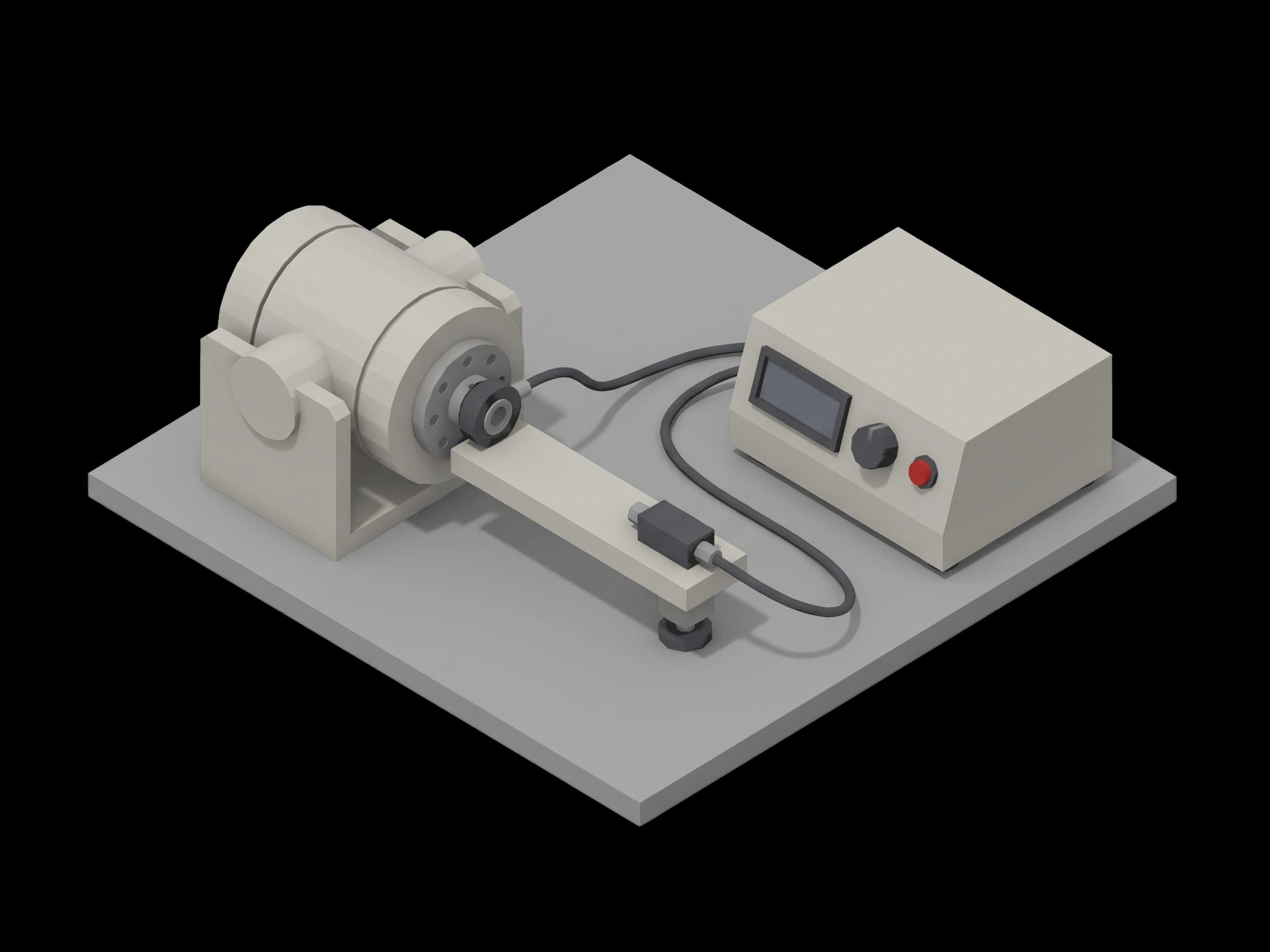
Get the complete source, dependencies and setup instructions from the template repository.
Open the source on GitHub ↗Introduction
Backlash and Stiffness Overview
A humanoid balances on its joints. What the controller sees as a torque command becomes, through the reducer, an angle at the foot, and the difference between the two is the reducer's lost motion and its compliance. A joint module with too much lost motion chatters at zero crossing; one with too little stiffness lags the controller under load; one whose transmission error has grown a new harmonic has a damaged flexspline or a bearing on its way out. The reducer makers define the three numbers precisely, in arc-minutes, and the joint module end-of-line test measures them on every unit with a reference encoder on the output shaft.
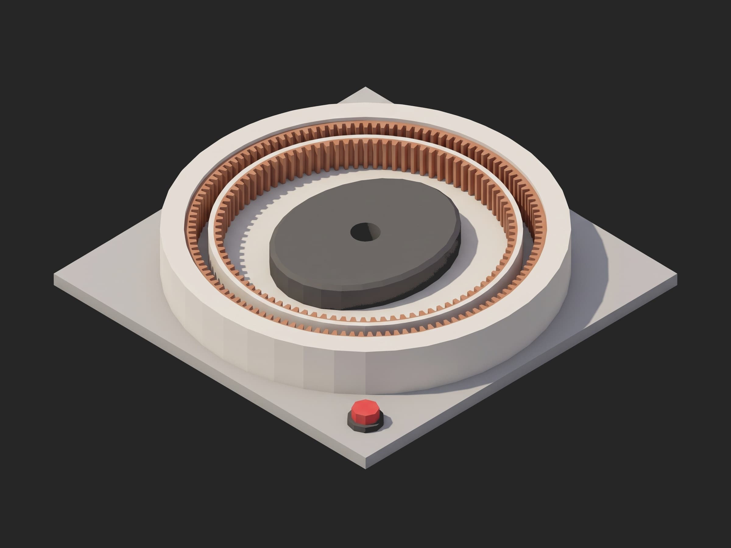
A strain-wave reducer from its output side: the flexspline's teeth engaged in the circular spline at the two lobes of the elliptical wave generator, which is why the transmission error of a healthy unit carries two cycles per input revolution.
The definitions come from the catalogs. Nabtesco specifies lost motion as the torsion angle read at ±3 % of rated torque on the hysteresis loop and quotes under 1 arc-min for its RV-E series (Nabtesco RV-E); Harmonic Drive literature uses ±4 %, and its hysteresis loss is the angle between the two branches of the loop at zero torque after loading to rated torque and back, 1.0 to 2.5 arc-min by size, with torsional stiffness piecewise, K1, K2, K3 between the breakpoints T1 and T2 (SHD catalog). Both makers give the numbers per size and ratio; the pack maker inherits them as limits. GB/T 35089-2018 gives a bench method for the precision reducer, and the Chinese EOL benches built to it read the output angle at ±1 arc-second.
Test Purpose
The procedure records one transmission fingerprint per joint module:
- Reference encoder self-check before anything is measured against it, and the input brake locked
- One full hysteresis loop, 0 to +rated to 0 to -rated to 0, output angle at every step
- From that loop: hysteresis loss at zero torque, lost motion at ±3 % of rated, and the three stiffness slopes K1, K2, K3
- Angular transmission error over one no-load output revolution: peak-to-peak, dominant order, once-per-revolution content
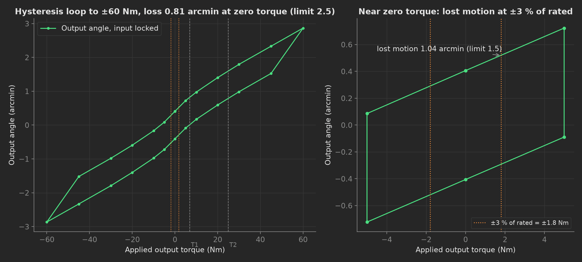
The mock module's loop: the slope steepens at T1 and again at T2 as the flexspline's teeth engage more deeply, the two branches sit 0.81 arc-min apart at zero torque, and the lost motion at ±1.8 Nm is 1.04 arc-min against a 1.5 arc-min limit for this grade.
The framework mechanics on show are five derived aggregations from one curve, each with its own limit; maker definitions coded rather than paraphrased; an integer aggregation validated with == on an FFT order; a reference instrument that proves itself in setup: before the DUT is measured; and a teardown: that releases the brake and the load.
Equipment & Setup
To run this test on a joint module line, the following are required:
- A reducer test bench with a locking brake on the input, a servo load actuator on the output and an inline torque transducer
- A reference encoder on the output shaft with arc-second resolution, independent of the module's own encoder
- The module's drive over EtherCAT for the no-load transmission-error sweep
- The Device Under Test (DUT): an assembled joint module, run in
- A TofuPilot Framework procedure to drive the loop, compute the maker-defined numbers and validate the limits
- The TofuPilot Dashboard to trend lost motion across modules, which is where a reducer lot change shows first
Hardware Components
Bench and Reference Encoder
Zekta's ZPRT-3 reducer acceptance bench cites GB/T 30819 and loads at 25, 50, 75, 100 and 125 % of rated; the Chengbang EOL4000 reads torque to ±0.05 % of full scale and angle to ±1 arc-second. The angle reference is the instrument that matters: a Heidenhain RCN 8000 or a Renishaw RESOLUTE 26-bit ring on the output shaft resolves 0.02 arc-second, three orders below the 1 arc-min the limits are written in. The module's own 19-bit output encoder resolves 2.5 arc-second and is the thing under test in the transmission-error sweep, not the reference.
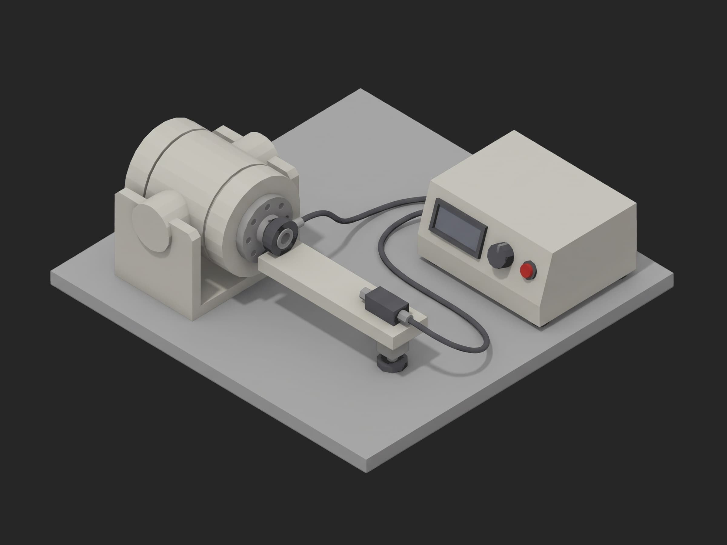
A single-axis station: the module clamped in its bracket with the input brake engaged, the load arm on the output flange, the reference ring on the output axis, the transducer and encoder cables into the instrument on the right.
Load Actuator and Transducer
The loop applies ±60 Nm at the output through a lever and a linear actuator, or through a coaxial servo load, with a Kistler 4503B or HBM T40B transducer in the path; class 0.05 on a 100 Nm range is 50 mNm, invisible against the 1.8 Nm the lost-motion definition sits at. The steps are held until the angle reading is static, which is what makes the test slow (minutes, not seconds) and what a spring-loaded shortcut gets wrong.
Where the Limits Come From
GB/T 35089-2018 and GB/T 30819-2024 give the method; the numbers come from the reducer maker's catalog for the size and ratio, then from the pack maker's own grade selection:
| Test | Limit | Basis |
|---|---|---|
| Hysteresis loss at zero torque | ≤ 2.5 arc-min | Harmonic Drive catalog range 1.0 to 2.5 arc-min by size |
| Lost motion at ±3 % of rated | ≤ 1.5 arc-min | Nabtesco definition; precision grade for this size |
| K1 (below T1) | ≥ 45 kNm/rad | catalog K1 minus 15 % |
| K2 (T1 to T2) | ≥ 60 kNm/rad | catalog K2 minus 25 % |
| K3 (above T2) | ≥ 70 kNm/rad | catalog K3 minus 25 % |
| Transmission error, no load | ≤ 1.5 arc-min p-p | catalog positional accuracy 1.0 to 1.5 arc-min |
| Dominant order | == 200 | 2 × ratio, the wave generator |
| Once-per-revolution content | ≤ 0.5 arc-min | a misaligned reference coupling or an eccentric flexspline |
The ±4 % lost-motion condition that circulates is the Harmonic Drive literature convention; the ±3 % one is Nabtesco's and is the one coded here, as a parameter. The "under 1 arc-min for life" line is a marketing figure; in a 57 hour endurance run on a quasi-direct-drive actuator, backlash grew from 56 to 82 mrad, which is why this template is also the pre/post measurement around a burn-in.
Test Procedure
Overview
The procedure maps the test onto the framework's three stages. The reference check and the brake live in setup: so no angle is recorded against an encoder with a bad signal or with the input free. Releasing lives in teardown: so the bench is never left loaded.
- Setup: reference encoder self-check, input brake locked.
- Main: hysteresis loop 0 to +60 to 0 to -60 to 0 Nm; hysteresis, lost motion, K1, K2, K3.
- Main: no-load transmission error over one revolution; p-p, dominant order, once-per-rev.
- Teardown: output unloaded, brake released.
Every metric validates against limits declared in procedure.yaml, and results stream to TofuPilot for trending.
Why TofuPilot Framework?
TofuPilot Framework is a YAML + Python test framework built for hardware manufacturing. Instead of writing all your test logic, measurements, and limits inside Python code, you describe what the test does in a procedure.yaml file, and how in small Python phase files. The framework handles:
- Automatic Python environment management (via
uv) - Operator UI (no frontend code needed)
- Measurement validation and live charts
- Process isolation between phases and equipment plugs
Project Structure
You can find the full source on GitHub. The JointBench plug is a mock of the brake, the load actuator, the transducer, the reference encoder and the module's drive together, synthesizing a healthy precision-grade module on catalog values, so the procedure runs end-to-end without a bench or a module connected.
tofupilot run .For CI or bench automation, the same run executes headless:
tofupilot run . --no-tui --no-kiosk --jsonThe Procedure File
procedure.yaml declares the unit, the bench plug, and the three stages with every measurement and limit:
procedure.yaml · 108 lines
name: Joint Module Backlash and Stiffness Testversion: 0.1.0description: Backlash, lost motion and torsional stiffness of a humanoid joint module on a 100:1 strain-wave reducer. Reference encoder self-check, a full hysteresis loop to rated torque both ways with the input locked, hysteresis loss and lost motion at +-3 % of rated, piecewise stiffness K1 K2 K3, and the no-load transmission error over one output revolution.unit: auto_identify: true serial_number: description: "Scan the joint module label" placeholder: "JM-KNE-000000" pattern: "^JM-[A-Z]{3}-\\d{6}$" default_value: "JM-KNE-002931" part_number: default_value: "JM-R100-60NM" batch_number: default_value: "WK-2026-37"plugs: - name: Joint Bench description: "Input brake, output torque actuator with inline transducer, 23-bit reference encoder, module drive (mock, one plug per bench)" python: plugs.joint_bench:JointBench key: benchsetup: - name: Reference Check key: reference_check python: phases.reference_check measurements: - name: Reference Signal key: reference_signal_pct unit: "%" description: Reference encoder signal level; below 70 % the arc-second accuracy is not there and nothing measured against it counts. validators: - {operator: ">=", expected_value: 70.0} - name: Reference Error key: reference_error validators: - {operator: "==", expected_value: false}main: - name: Hysteresis Loop key: hysteresis_loop python: phases.hysteresis_loop timeout: 5m measurements: - name: Loop key: loop title: Output angle against applied torque, input locked, 0 to +60 to 0 to -60 to 0 Nm x_axis: legend: Torque unit: Nm y_axis: - legend: Angle key: angle unit: arcmin aggregations: - type: hysteresis_arcmin unit: arcmin validators: - {operator: "<=", expected_value: 2.5} - type: lost_motion_arcmin unit: arcmin validators: - {operator: "<=", expected_value: 1.5} - type: k1_knm_per_rad unit: kNm/rad validators: - {operator: ">=", expected_value: 45.0} - type: k2_knm_per_rad unit: kNm/rad validators: - {operator: ">=", expected_value: 60.0} - type: k3_knm_per_rad unit: kNm/rad validators: - {operator: ">=", expected_value: 70.0} - name: Transmission Error key: transmission_error python: phases.transmission_error depends_on: [hysteresis_loop] measurements: - name: TE key: te title: Reference minus module encoder over one no-load output revolution x_axis: legend: Output angle unit: ° y_axis: - legend: Transmission error key: te unit: arcmin aggregations: - type: pp_arcmin unit: arcmin validators: - {operator: "<=", expected_value: 1.5} - type: dominant_order validators: - {operator: "==", expected_value: 200} - type: low_order_arcmin unit: arcmin validators: - {operator: "<=", expected_value: 0.5}teardown: - name: Release key: release python: phases.releaseFramework features to notice:
- Five numbers from one curve. The loop is recorded once; hysteresis, lost motion and the three stiffnesses are aggregations computed in Python and named in the YAML, each with its own limit. A failing module says which one.
- The definition is in the code.
LOST_MOTION_FRACTION = 0.03in the recipe and the interpolation in the phase are Nabtesco's definition; switching to the ±4 % convention is one constant. - An FFT order as an integer
==.dominant_order == 200says the transmission error is the wave generator's, and nothing else has overtaken it. - The reference proves itself first. The signal level and error flag of the reference encoder are validated in
setup:; a measurement against a degraded reference never reaches the report.
Reference Check
The setup phase reads the reference encoder's signal level and error flag, locks the input brake, and stamps the reducer grade onto the unit metadata:
def reference_check(measurements, bench, unit, log): """Setup: the reference encoder proves itself before anything is measured against it; the input brake locks the motor side.""" ref = bench.reference_encoder_ok() measurements.reference_signal_pct = ref["level_pct"] measurements.reference_error = ref["error"] bench.lock_input() unit.metadata["reducer_grade"] = "precision" log.info(f"Module {unit.serial_number}: reference encoder at {ref['level_pct']} % signal, input locked")Hysteresis Loop
Torque stepped through 0, 5, 10, 20, 30, 45, 60 Nm and back, then the same negative, with the input locked and the output angle read at every step once static. The phase separates the loading and unloading branches, reads the hysteresis loss as the gap at zero torque, the lost motion as the angle between the +3 % and -3 % crossings, and fits the three slopes between the catalog breakpoints:
phases/hysteresis_loop.py · 41 lines
import numpy as npfrom utils.recipe import LOOP_STEPS_NM, LOST_MOTION_FRACTION, RATED_TORQUE_NM, T1_NM, T2_NMdef hysteresis_loop(measurements, bench, log): """Torque stepped 0 -> +rated -> 0 -> -rated -> 0 with the input locked, output angle from the reference encoder. From one loop: hysteresis loss at rated torque, lost motion at +-3 % of rated, and the three stiffness slopes K1, K2, K3 between the catalog breakpoints.""" loop = bench.hysteresis_loop(LOOP_STEPS_NM) t = np.array(loop["torque_nm"]) a = np.array(loop["angle_arcmin"]) n = len(LOOP_STEPS_NM) # Loading branch and unloading branch of the positive half. load_t, load_a = t[:n], a[:n] unload_t, unload_a = t[n - 1:2 * n - 1], a[n - 1:2 * n - 1] hyst = float(np.interp(0.0, unload_t[::-1], unload_a[::-1]) - np.interp(0.0, load_t, load_a)) # Full loop: lost motion is the angle between the +3 % and -3 % crossings. lm_t = LOST_MOTION_FRACTION * RATED_TORQUE_NM a_plus = float(np.interp(lm_t, load_t, load_a)) neg_load_t, neg_load_a = t[2 * n - 2:3 * n - 2], a[2 * n - 2:3 * n - 2] a_minus = float(np.interp(-lm_t, neg_load_t[::-1], neg_load_a[::-1])) lost_motion = a_plus - a_minus def slope(lo, hi): m = (load_t >= lo) & (load_t <= hi) k, _ = np.polyfit(load_t[m], np.deg2rad(load_a[m] / 60.0), 1) return float(1.0 / k) k1, k2, k3 = slope(0.0, T1_NM), slope(T1_NM, T2_NM), slope(T2_NM, RATED_TORQUE_NM) measurements.loop.x_axis = loop["torque_nm"] measurements.loop.y_axis.angle = loop["angle_arcmin"] measurements.loop.y_axis.angle.aggregations.hysteresis_arcmin = abs(hyst) measurements.loop.y_axis.angle.aggregations.lost_motion_arcmin = lost_motion measurements.loop.y_axis.angle.aggregations.k1_knm_per_rad = k1 / 1000.0 measurements.loop.y_axis.angle.aggregations.k2_knm_per_rad = k2 / 1000.0 measurements.loop.y_axis.angle.aggregations.k3_knm_per_rad = k3 / 1000.0 log.info(f"Hysteresis {abs(hyst):.2f} arcmin, lost motion {lost_motion:.2f} arcmin at +-{lm_t:.1f} Nm, K1/K2/K3 {k1/1000:.0f}/{k2/1000:.0f}/{k3/1000:.0f} kNm/rad")Transmission Error
The brake is released and the module drives one output revolution at no load, the reference encoder minus the module's own encoder recorded every 0.5°. The peak-to-peak is the angular transmission error; the FFT over the revolution gives the dominant order, which is twice the ratio for a strain-wave reducer, and the once-per-revolution content, which a misaligned reference coupling or an eccentric flexspline raises:
phases/transmission_error.py · 22 lines
import numpy as npfrom utils.recipe import RATIO, TRANSMISSION_ERROR_POINTSdef transmission_error(measurements, bench, log): """Input released, module drives one output revolution at no load, reference encoder minus module encoder every 0.5 deg. Peak-to-peak is the angular transmission error; its dominant order says which part of the drivetrain produced it: 2 x ratio is the wave generator.""" bench.release_input() sweep = bench.transmission_error_sweep(TRANSMISSION_ERROR_POINTS) te = np.array(sweep["te_arcmin"]) spectrum = np.abs(np.fft.rfft(te - te.mean())) order = int(np.argmax(spectrum[1:]) + 1) low_order = float(2.0 * spectrum[1:4].max() / len(te)) measurements.te.x_axis = sweep["angle_deg"] measurements.te.y_axis.te = sweep["te_arcmin"] measurements.te.y_axis.te.aggregations.pp_arcmin = float(te.max() - te.min()) measurements.te.y_axis.te.aggregations.dominant_order = order measurements.te.y_axis.te.aggregations.low_order_arcmin = low_order log.info(f"Transmission error {te.max() - te.min():.2f} arcmin p-p, dominant order {order} (2 x ratio = {2 * RATIO}), once-per-rev content {low_order:.2f} arcmin")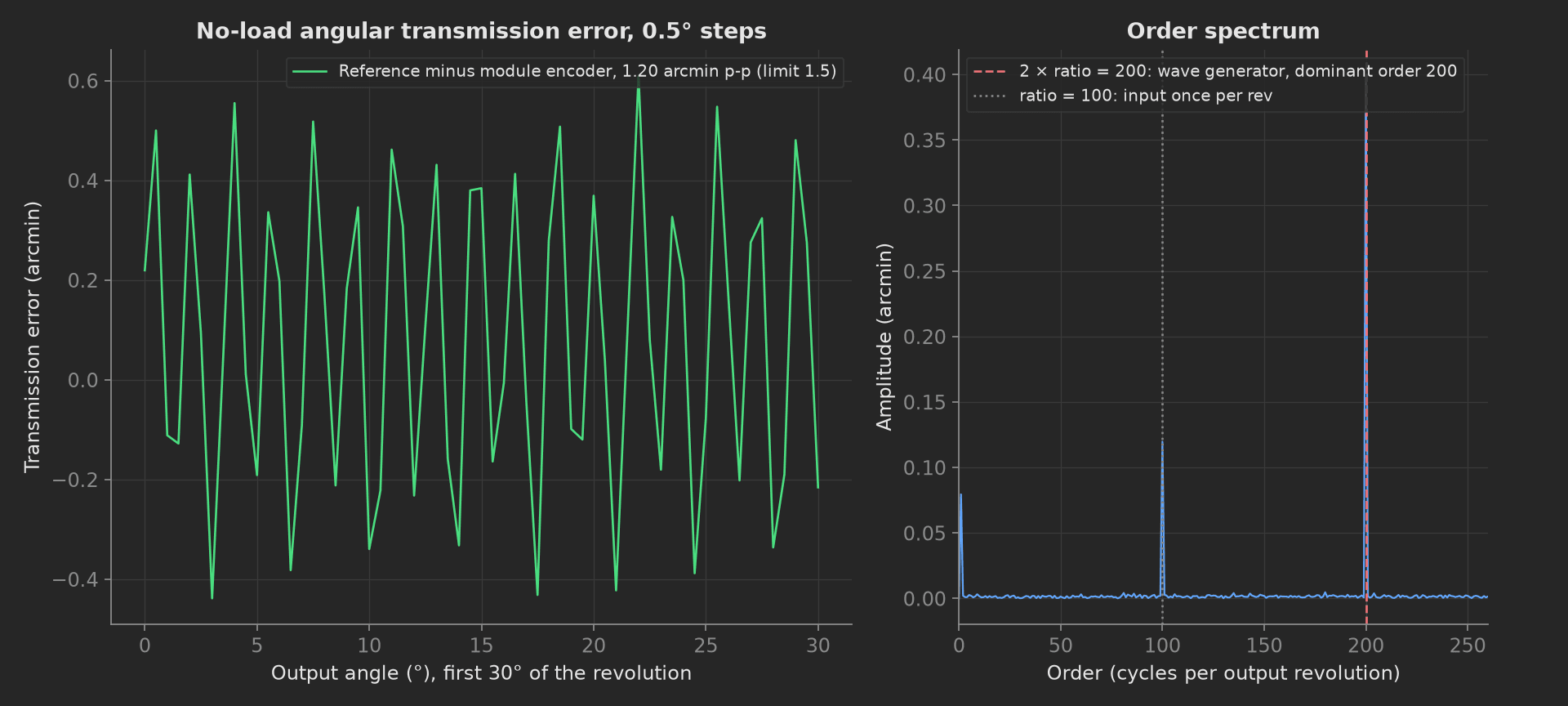
The mock's transmission error: 1.20 arc-min peak-to-peak against a 1.5 limit, the wave generator at order 200 dominant, the input's once-per-revolution at order 100 a third of it, and 0.08 arc-min of once-per-output-revolution content.
Release
The teardown phase unloads the output and releases the brake, whatever the outcome:
def release(bench, log): """Teardown: output unloaded, brake released.""" bench.unload() bench.release_input() log.info("Unloaded, brake released")Mock Plug
JointBench stands in for the brake, the load actuator, the transducer, the reference encoder and the module's drive. It synthesizes a piecewise-linear wind-up with K1 = 54, K2 = 81, K3 = 96 kNm/rad and breakpoints at 7 and 25 Nm, a hysteresis loop 0.85 arc-min wide at zero torque, a transmission error of 0.40 arc-min amplitude at order 200 with 0.12 at order 100 and 0.08 at order 1, and a reference encoder at 94 % signal. Every method returns plain Python types because plug calls cross a JSON boundary; a measurement read back from measurements.<key> returns a proxy, so the phases keep locals for their log lines.
On a real bench, the class speaks to the bench PLC for the brake and the load steps, reads the transducer through the DAQ, the reference ring through its EnDat or BiSS interface, and the module's encoder over EtherCAT. Hold each torque step until the angle is static, run the loop in both directions, and record the reducer lot on the unit so the lost-motion trend can be cut by lot. The phases, measurements and limits stay the same.