
Get the complete source, dependencies and setup instructions from the template repository.
Open the source on GitHubIntroduction
Intrinsic Calibration Overview
A camera module turns a 3D point into a pixel through the pinhole model and the lens distortion. The pinhole part is the intrinsic matrix: focal lengths fx, fy in pixels and the principal point cx, cy where the optical axis meets the sensor. The lens part is the Brown-Conrady polynomial: radial terms k1, k2, k3 (barrel or pincushion) and tangential terms p1, p2 (lens decentring and tilt). Every module leaves the line with its own set: the lens sits a few micrometres off the sensor centre, the focal length varies with the glue thickness, the distortion with the lens batch. A 6 mm lens on a 1/2.3-inch sensor puts a corner point about 140 px away from where a perfect pinhole would, so any application that measures, maps, or navigates with the image needs the per-module coefficients, not the datasheet.
Intrinsic calibration recovers them from images of a target of known geometry. The module looks at a ChArUco board (a chessboard with ArUco markers in the white squares, so every corner has an identity even when the board is partly out of frame) from several poses; the corners are detected to sub-pixel precision; cv2.calibrateCamera fits the model that best reprojects all of them at once. The residual, the reprojection error, is the quality figure: below 0.3 px RMS on a 1080p sensor is a good module and a good fit.
Test Purpose
The procedure produces, per module:
- Identity: serial read back from the module EEPROM against the scanned label, sensor and lens stamped on the unit
- Capture record: 16 calibration poses plus 3 held-out poses, corners detected per pose, sensor coverage across a 6 by 4 grid of cells
- The fit: fx, fy, cx, cy, k1, k2, k3, p1, p2 with two-sided limits, RMS reprojection error, per-pose error with the maximum validated
- Independent validation: reprojection on the 3 held-out poses with the pose solved from the calibrated model, straightness of an undistorted board row, horizontal field of view
- Persistence: the coefficients written to the module EEPROM, read back and compared, the calibration ID on the unit
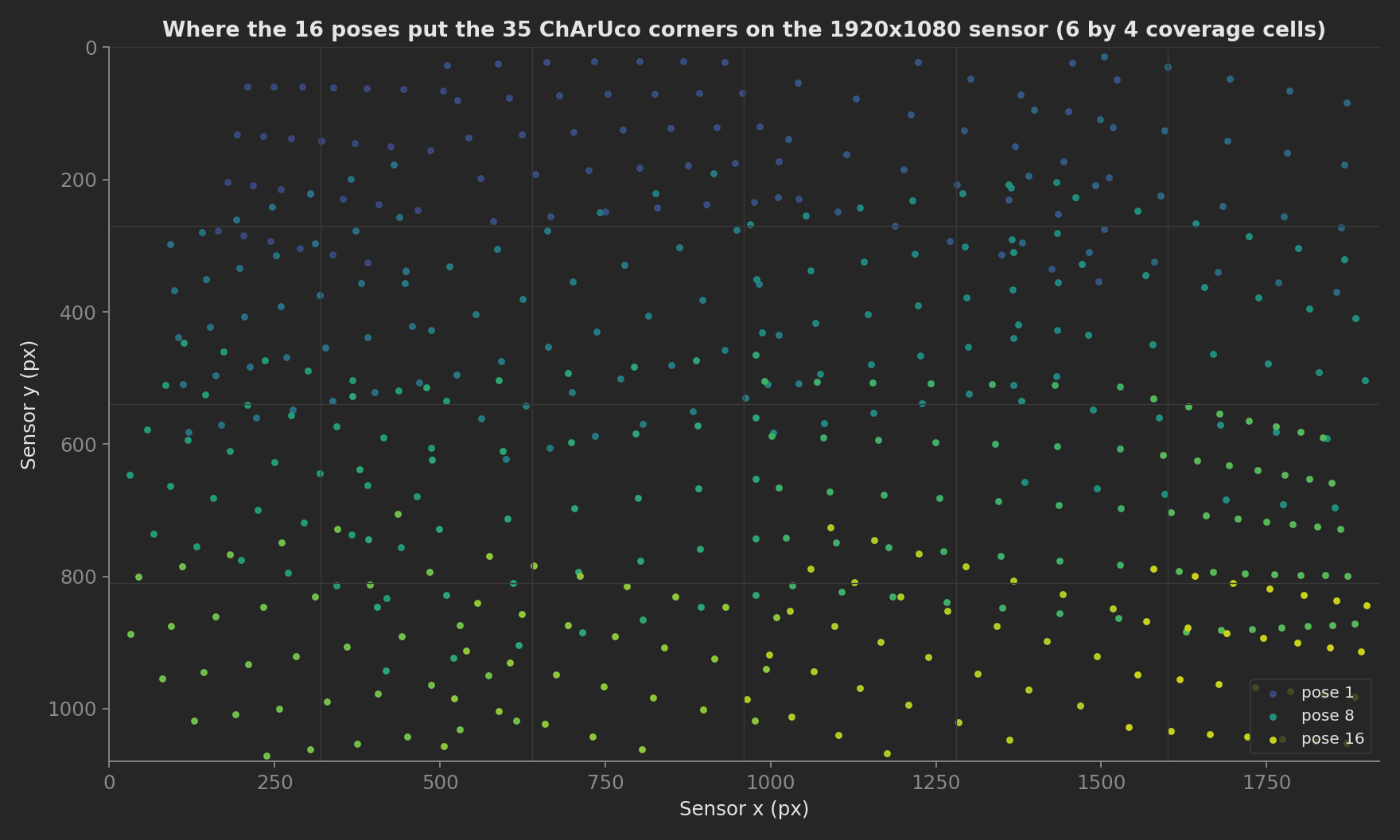
Where the 16 poses put the corners on the sensor in one run of the mock: every one of the 24 coverage cells sees corners, including the borders where distortion is largest and a fit with centre-only data goes wrong.
Defects this catches before the module ships: a decentred lens (principal point outside its window), a wrong or badly seated lens (focal length or field of view off), a tilted lens (tangential terms above limit), a contaminated or scratched front element (corners lost, per-pose error up), and a bad EEPROM (read-back mismatch).
Beyond the calibration content, the template shows five framework mechanics: a setup phase stamping unit.metadata from the module, an operator UI progress bar over the 16 poses, multi-dimensional measurements with custom aggregations (min_corners, max_px) validated in YAML, nine numeric measurements from one fit with two-sided limits, and attach.file of the calibration file on the run.
Equipment & Setup
To calibrate camera modules on a production line, the following are required:
- A calibration target: a ChArUco or chessboard chart, printed on glass or dibond, flat to better than 0.1 mm, backlit for constant contrast
- A target stage: a motorised tilt and slide head so the chart appears at different poses, or a fixed chart and a moving module
- A module fixture: a nest with pogo pins for power and MIPI, a bridge to the test PC
- The Devices Under Test: assembled camera modules, lens glued and cured, EEPROM blank
- A TofuPilot Framework procedure to drive the stage, capture, fit, validate and write
- The TofuPilot Dashboard to keep every module's coefficients and trend them per lens batch
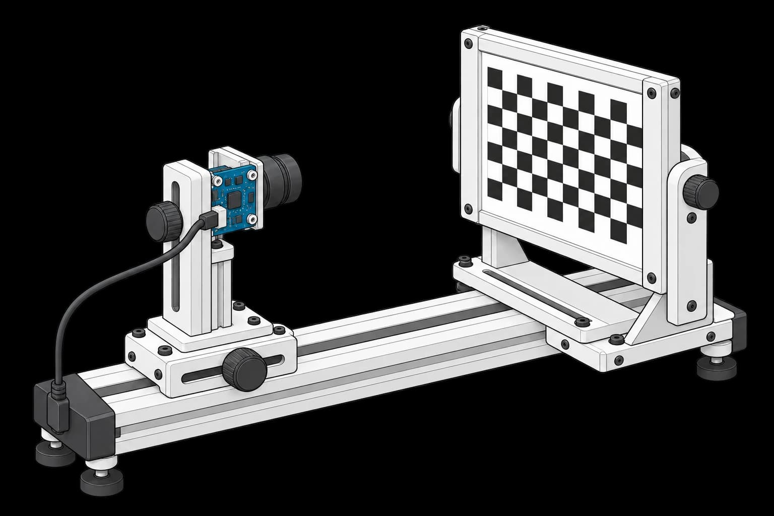
The module and target share an adjustable optical rail. The board is supported on insulated mounts; illumination control and the test computer are omitted.
Hardware Components
Calibration Targets
Calib.io and Image Engineering sell ChArUco and chessboard charts on glass with certified flatness and square pitch. ChArUco (a chessboard with an ArUco marker in every white square, OpenCV's cv2.aruco.CharucoBoard) is the production choice because every corner carries an ID: partial views at the sensor border still contribute, which is exactly where the distortion terms need data. The template's board is 8 by 6 squares of 30 mm, 35 inner corners.
Target Stage and Module Fixture
A two-axis tilt head with a slide covers the poses a calibration needs: tilts to ±30° on both axes, distances from 0.35 to 0.6 m, the board centre walked over the field. Vendors of complete camera test stations, TRIOPTICS (CamTest Chart), Image Engineering and Radiant Vision Systems, integrate the chart, the illumination and the fixture in one cabinet and add MTF, boresight and relative illumination on the same frames. The module fixture is a machined nest with pogo pins on the board edge and a MIPI-to-USB bridge (Leopard Imaging, e-con Systems, or the SoC vendor's) to the test PC.
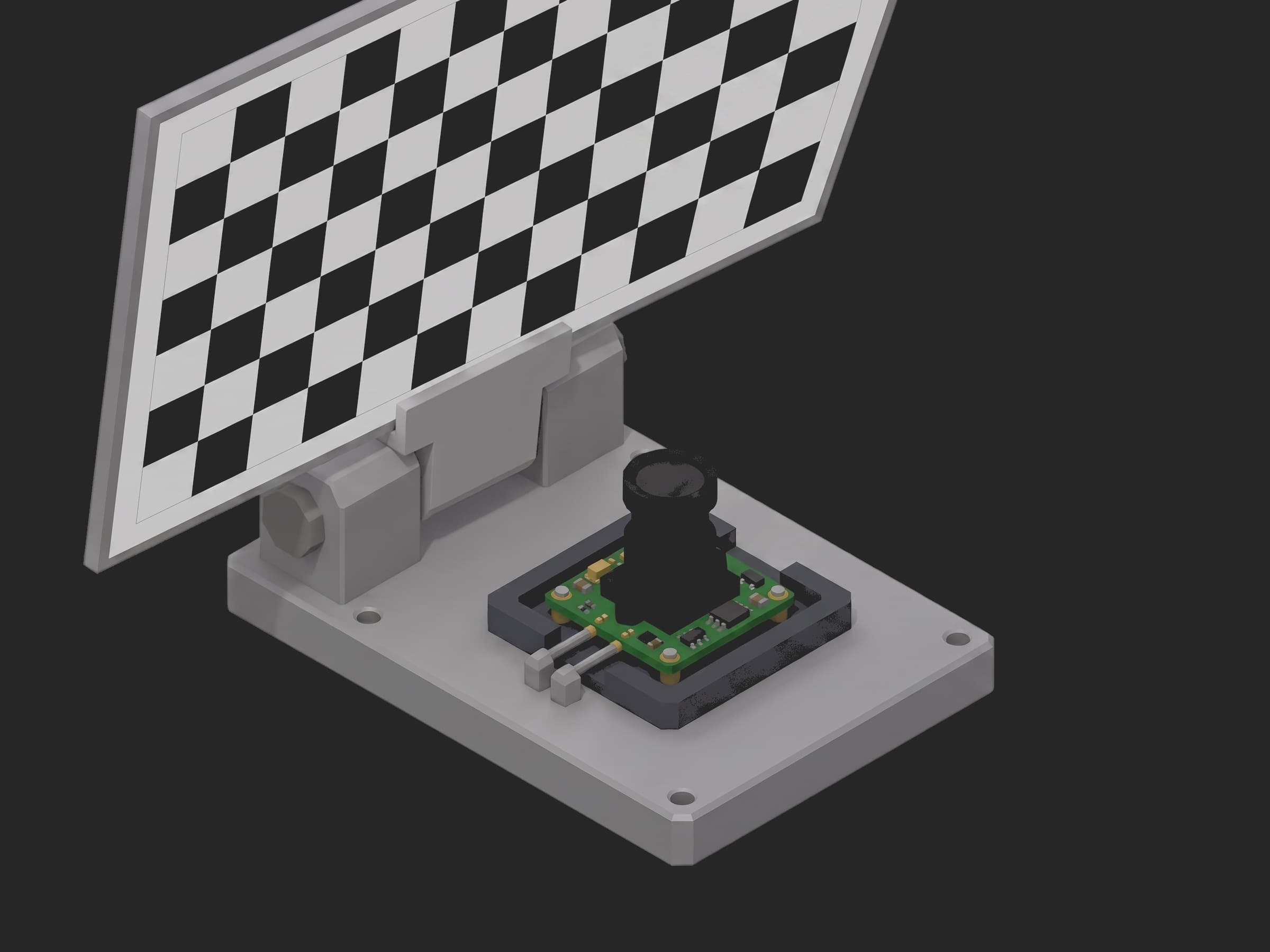
The module in its nest, two pogo pins on the board edge, the chart tilted above it. Each pose is one frame, one detection, one row in the capture record.
Limits
Limits for a 6 mm f/2.0 lens on a 1920 by 1080 sensor with 1.55 µm pixels, as the template ships them:
| Parameter | Limit | Why |
|---|---|---|
| Reprojection RMS | ≤ 0.30 px | detector noise plus model error on a good module |
| Per-pose RMS max | ≤ 0.50 px | one bad pose (blur, glare) fails the run, not the average |
| fx, fy | 1400 to 1500 px | nominal 1452 px, ±3.5 % covers glue thickness and lens tolerance |
| fy / fx | 0.995 to 1.005 | square pixels; outside means a tilted sensor or a bad fit |
| cx, cy | 930 to 990, 510 to 570 px | ±30 px around the sensor centre, a decentred lens fails here |
| k1, k2, k3 | −0.35 to −0.20, 0.02 to 0.20, −0.10 to 0.05 | the lens design's barrel signature |
| p1, p2 | ±0.002 | tangential terms above this mean a tilted lens |
| Held-out RMS | ≤ 0.40 px | the model must generalise to poses it never saw |
| Line straightness | ≤ 0.50 px | undistorted rows must come out straight across the full width |
| Horizontal FOV | 64° to 70° | derived from fx, catches a wrong lens outright |
Custom Firmware
The module runs its stock sensor firmware; capture is a raw frame over MIPI. The only module-side feature the procedure needs is a writable EEPROM (typically 256 bytes on the module's I2C bus) where the coefficients are stored for the host driver to read at boot. Modules without EEPROM keep the calibration in the host's database keyed by serial, which the run record already is.
Test Procedure
Overview
For each module in the fixture, the procedure runs:
- Setup: open the module, read serial, sensor, lens, resolution and temperature.
- Drive the stage through 16 calibration poses and 3 held-out poses, detect the ChArUco corners at each, check sensor coverage.
- Fit the pinhole model and five distortion coefficients with OpenCV, validate every coefficient, the RMS and the per-pose errors.
- Solve the pose of the 3 held-out views with the fitted model and check their reprojection, the straightness of undistorted board rows, and the field of view.
- Write the coefficients to the module EEPROM, read them back, compare.
- Teardown: home the stage and close the module.
Why TofuPilot Framework?
TofuPilot Framework is a YAML + Python test framework built for hardware manufacturing. Instead of writing all your test logic, measurements, and limits inside Python code, you describe what the test does in a procedure.yaml file, and how in small Python phase files. The framework handles:
- Automatic Python environment management (via
uv) - Operator UI (no frontend code needed)
- Measurement validation and live charts
- Process isolation between phases and equipment plugs
Project Structure
The module and the stage are mocks; the calibration is real OpenCV, run by the framework in a uv environment with numpy and opencv-python-headless. Run it with tofupilot run . --no-tui --no-kiosk --json. You can find the full source on GitHub.
The Procedure File
This is the exact file the template ships, verified end to end with the CLI:
procedure.yaml219 lines
name: Camera Module Intrinsic Calibrationversion: 0.1.0description: Calibrates a camera module's intrinsics and lens distortion on a ChArUco target, validates the model on held-out views, and writes the coefficients to the module EEPROM.unit: auto_identify: true serial_number: description: "Scan the module label" placeholder: "CAM-000000" pattern: "^CAM-\\d{6}$" default_value: "CAM-041872" part_number: default_value: "CAM-IMX477-6MM" metadata: sensor: description: "Sensor model read from the module" lens: description: "Lens focal length and f-number read from the module" calibration_id: description: "Identifier of the calibration written to the EEPROM"plugs: - name: Camera Module description: "Module under test over the fixture's MIPI to USB bridge: frames, EEPROM, temperature (mock)" python: plugs.camera:CameraModule key: camera - name: Target Stage description: Motorised tilt and slide stage holding the ChArUco target (mock) python: plugs.stage:TargetStage key: stagesetup: - name: Connect Module key: connect_module python: phases.connect_module measurements: - name: Module Serial key: module_serial description: "Serial read from the module EEPROM, must match the scanned label" validators: - {operator: matches, expected_value: "^CAM-\\d{6}$"} - name: Sensor Temperature key: sensor_temperature unit: °C validators: - {operator: ">=", expected_value: 15.0} - {operator: "<=", expected_value: 45.0} - name: Resolution key: resolution validators: - {operator: "==", expected_value: "1920x1080"}main: - name: Capture Views key: capture_views python: phases.capture_views ui: components: - key: capture_progress type: progress label: "Target poses" description: "16 poses, tilt and slide" default_value: 0 max: 100 measurements: - name: Views Captured key: views_captured validators: - {operator: "==", expected_value: 16} - name: Corners per View key: corners_per_view title: Detected ChArUco corners per pose x_axis: legend: Pose y_axis: - legend: Corners key: corners aggregations: - type: min_corners validators: - {operator: ">=", expected_value: 20} - name: Sensor Coverage key: coverage_pct unit: "%" description: "Share of a 6 by 4 grid of sensor cells that saw at least one corner across all poses" validators: - {operator: ">=", expected_value: 85.0} - name: Calibrate key: calibrate python: phases.calibrate depends_on: [capture_views] measurements: - name: Reprojection RMS key: rms_px unit: px validators: - {operator: "<=", expected_value: 0.30} - name: Reprojection Error per View key: view_error title: Reprojection error per pose x_axis: legend: Pose y_axis: - legend: RMS key: error unit: px aggregations: - type: max_px unit: px validators: - {operator: "<=", expected_value: 0.50} - name: Focal Length X key: fx unit: px validators: - {operator: ">=", expected_value: 1400.0} - {operator: "<=", expected_value: 1500.0} - name: Focal Length Y key: fy unit: px validators: - {operator: ">=", expected_value: 1400.0} - {operator: "<=", expected_value: 1500.0} - name: Pixel Aspect key: pixel_aspect description: "fy over fx, square pixels expected" validators: - {operator: ">=", expected_value: 0.995} - {operator: "<=", expected_value: 1.005} - name: Principal Point X key: cx unit: px validators: - {operator: ">=", expected_value: 930.0} - {operator: "<=", expected_value: 990.0} - name: Principal Point Y key: cy unit: px validators: - {operator: ">=", expected_value: 510.0} - {operator: "<=", expected_value: 570.0} - name: Radial k1 key: k1 validators: - {operator: ">=", expected_value: -0.35} - {operator: "<=", expected_value: -0.20} - name: Radial k2 key: k2 validators: - {operator: ">=", expected_value: 0.02} - {operator: "<=", expected_value: 0.20} - name: Radial k3 key: k3 validators: - {operator: ">=", expected_value: -0.10} - {operator: "<=", expected_value: 0.05} - name: Tangential p1 key: p1 validators: - {operator: ">=", expected_value: -0.002} - {operator: "<=", expected_value: 0.002} - name: Tangential p2 key: p2 validators: - {operator: ">=", expected_value: -0.002} - {operator: "<=", expected_value: 0.002} - name: Camera Matrix key: camera_matrix description: "The 3 by 3 intrinsic matrix as fitted, kept whole for the record" - name: Verify on Held-Out Views key: verify_holdout python: phases.verify_holdout depends_on: [calibrate] measurements: - name: Held-Out Reprojection RMS key: holdout_rms_px unit: px description: "Reprojection error on 3 poses the fit never saw, with the pose solved from the calibrated model" validators: - {operator: "<=", expected_value: 0.40} - name: Line Straightness key: line_straightness_px unit: px description: "Max deviation from a straight line of an undistorted board row across the full width" validators: - {operator: "<=", expected_value: 0.50} - name: Field of View key: hfov_deg unit: ° validators: - {operator: ">=", expected_value: 64.0} - {operator: "<=", expected_value: 70.0} - name: Write EEPROM key: write_eeprom python: phases.write_eeprom depends_on: [verify_holdout] measurements: - name: EEPROM Verified key: eeprom_verified description: "Coefficients read back from the module equal what was written" validators: - {operator: "==", expected_value: true} - name: Calibration ID key: calibration_id validators: - {operator: matches, expected_value: "^CAL-[0-9A-F]{8}$"}teardown: - name: Release Module key: release_module python: phases.release_module measurements: - name: Stage Homed key: stage_homed validators: - {operator: "==", expected_value: true}Framework features to notice:
- Setup stamps the unit:
connect_modulereads the module and writesunit.metadata["sensor"]and["lens"], declared underunit.metadatain the YAML, so a run can be filtered by lens batch later. - Progress over a long phase: the
capture_progresscomponent is bound to nothing but updated from the phase (ui.capture_progress = ...) as the stage walks the 16 poses. - Multi-dimensional measurements with custom aggregations:
corners_per_viewvalidates itsmin_corners,view_erroritsmax_px; the aggregation names are the phase's own, computed in Python and checked in YAML. - One fit, nine validated numbers: fx, fy, cx, cy, k1, k2, k3, p1, p2 each carry their own two-sided limit, so the run page says which coefficient a bad module failed on, and the camera matrix is also kept whole as a JSON measurement.
- String and boolean validators:
resolutioncompared as"1920x1080"with==,module_serialandcalibration_idwithmatches,eeprom_verifiedas a boolean. One thing learned on the way: an array measurement compared with==to[1920, 1080]fails because the recorded integers come back as floats; a string is the safe form.
Capture Views
The stage yields 16 calibration poses walking the board centre over a 4 by 4 grid of the field, plus 3 random held-out poses. At each, the module returns the corner detections; the phase counts them, tracks which sensor cells have seen a corner, and advances the progress bar. The detections go to the next phases through a file, not through the measurement record, since a measurement is not the place for 700 corner coordinates:
phases/capture_views.py37 lines
import jsonfrom utils.board import IMAGE_SIZEN_VIEWS = 16N_HOLDOUT = 3GRID = (6, 4) # sensor cells for the coverage checkdef capture_views(measurements, camera, stage, ui, log): """Drive the target through 16 calibration poses plus 3 held-out poses, capture the detections at each.""" poses = stage.poses(N_VIEWS + N_HOLDOUT) views = [] counts = [] seen = set() w, h = IMAGE_SIZE for i, pose in enumerate(poses): stage.move_to(i) det = camera.capture(pose["rvec"], pose["tvec"]) views.append({"pose": i, "ids": det["ids"], "corners": det["corners"]}) if i < N_VIEWS: counts.append(len(det["ids"])) for x, y in det["corners"]: seen.add((int(x * GRID[0] / w), int(y * GRID[1] / h))) ui.capture_progress = int(100 * (i + 1) / N_VIEWS) coverage = 100.0 * len(seen) / (GRID[0] * GRID[1]) log.info(f"{N_VIEWS} calibration poses, {min(counts)}-{max(counts)} corners each, {coverage:.0f} % sensor coverage, {N_HOLDOUT} held-out poses") measurements.views_captured = N_VIEWS measurements.corners_per_view.x_axis = list(range(1, N_VIEWS + 1)) measurements.corners_per_view.y_axis.corners = counts measurements.corners_per_view.y_axis.corners.aggregations.min_corners = min(counts) measurements.coverage_pct = coverage # the detections go to the next phases through a file, not through the measurement record with open("views.json", "w") as f: json.dump({"calibration": views[:N_VIEWS], "holdout": views[N_VIEWS:]}, f)On the mock the poses yield 23 to 35 corners each and 100 % coverage. A pose that loses corners to the border still counts, that is what the ChArUco IDs are for; a pose under 20 corners fails min_corners and points at glare or a blurred frame.
Calibrate
cv2.calibrateCamera takes the object points of the detected corners (board frame, metres) and their image points for all 16 poses and returns the intrinsic matrix, the distortion vector, and the pose of every view. The phase then reprojects each view with the fitted model to get the per-pose error, records every coefficient, and attaches the calibration file:
phases/calibrate.py55 lines
import jsonimport cv2import numpy as npfrom utils.board import IMAGE_SIZE, object_pointsdef calibrate(measurements, attach, log): """Fit the pinhole model and five distortion coefficients to the 16 calibration views.""" with open("views.json") as f: views = json.load(f)["calibration"] board = object_points() obj_pts = [board[v["ids"]] for v in views] img_pts = [np.asarray(v["corners"], dtype=np.float32).reshape(-1, 1, 2) for v in views] rms, K, dist, rvecs, tvecs = cv2.calibrateCamera(obj_pts, img_pts, IMAGE_SIZE, None, None) dist = dist.ravel() per_view = [] for o, i, r, t in zip(obj_pts, img_pts, rvecs, tvecs): proj, _ = cv2.projectPoints(o, r, t, K, dist) per_view.append(float(np.sqrt(np.mean(np.sum((proj - i) ** 2, axis=2))))) fx, fy, cx, cy = float(K[0, 0]), float(K[1, 1]), float(K[0, 2]), float(K[1, 2]) k1, k2, p1, p2, k3 = (float(x) for x in dist[:5]) log.info(f"RMS {rms:.3f} px, fx {fx:.1f} fy {fy:.1f} cx {cx:.1f} cy {cy:.1f}, k1 {k1:.4f} k2 {k2:.4f} k3 {k3:.4f} p1 {p1:.5f} p2 {p2:.5f}") measurements.rms_px = float(rms) measurements.view_error.x_axis = list(range(1, len(per_view) + 1)) measurements.view_error.y_axis.error = per_view measurements.view_error.y_axis.error.aggregations.max_px = max(per_view) measurements.fx = fx measurements.fy = fy measurements.pixel_aspect = fy / fx measurements.cx = cx measurements.cy = cy measurements.k1 = k1 measurements.k2 = k2 measurements.k3 = k3 measurements.p1 = p1 measurements.p2 = p2 measurements.camera_matrix = {"fx": round(fx, 3), "fy": round(fy, 3), "cx": round(cx, 3), "cy": round(cy, 3), "skew": 0.0} calibration = { "model": "opencv_pinhole_5", "image_size": list(IMAGE_SIZE), "camera_matrix": [[fx, 0.0, cx], [0.0, fy, cy], [0.0, 0.0, 1.0]], "distortion": [k1, k2, p1, p2, k3], "rms_px": float(rms), "views": len(views), } with open("calibration.json", "w") as f: json.dump(calibration, f, indent=2) attach.file("calibration.json", "calibration.json")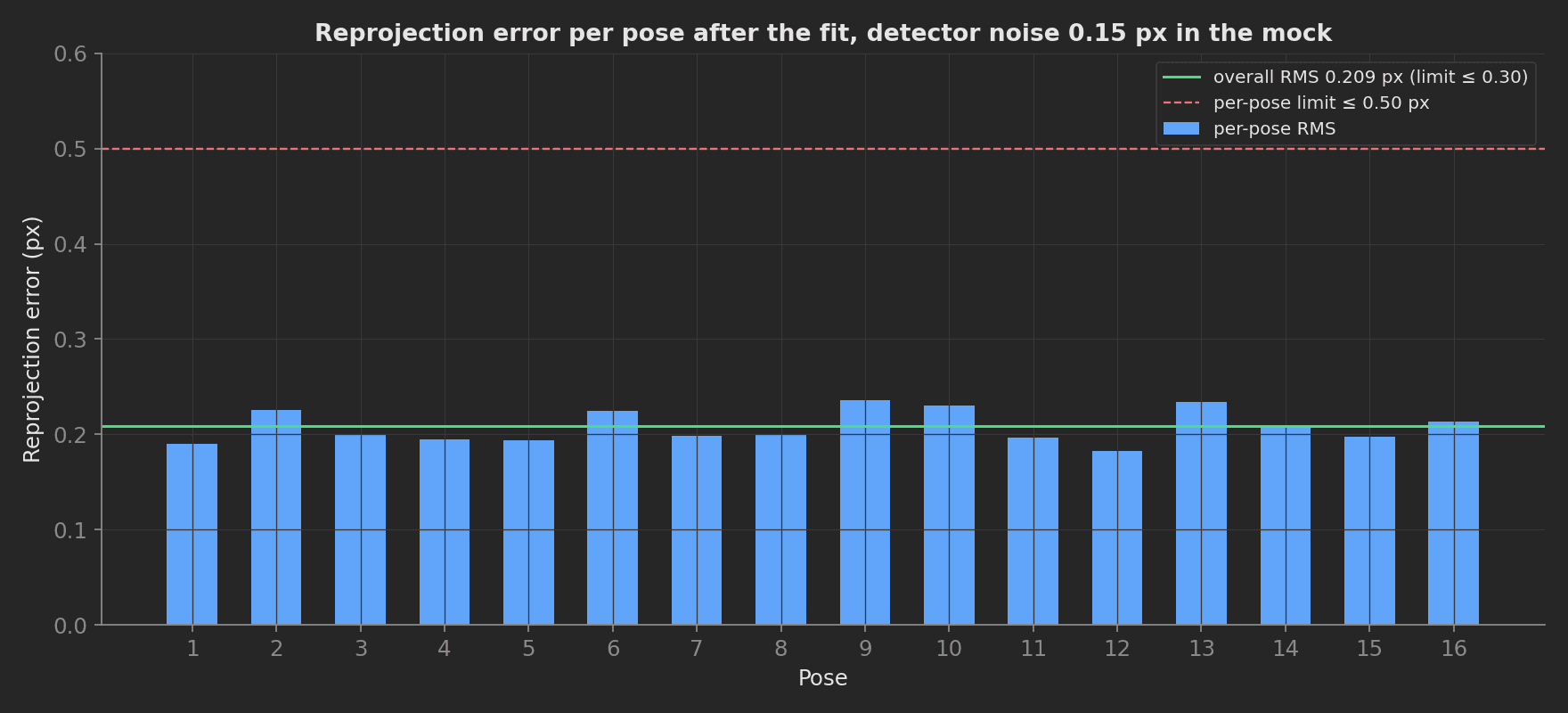
The per-pose errors of the mock run: 0.18 to 0.24 px on every pose, overall RMS 0.209 px, with 0.15 px of detector noise built into the mock. A single pose at 0.5 px with the others at 0.2 px is a bad frame, not a bad module; the max_px aggregation fails that case explicitly.
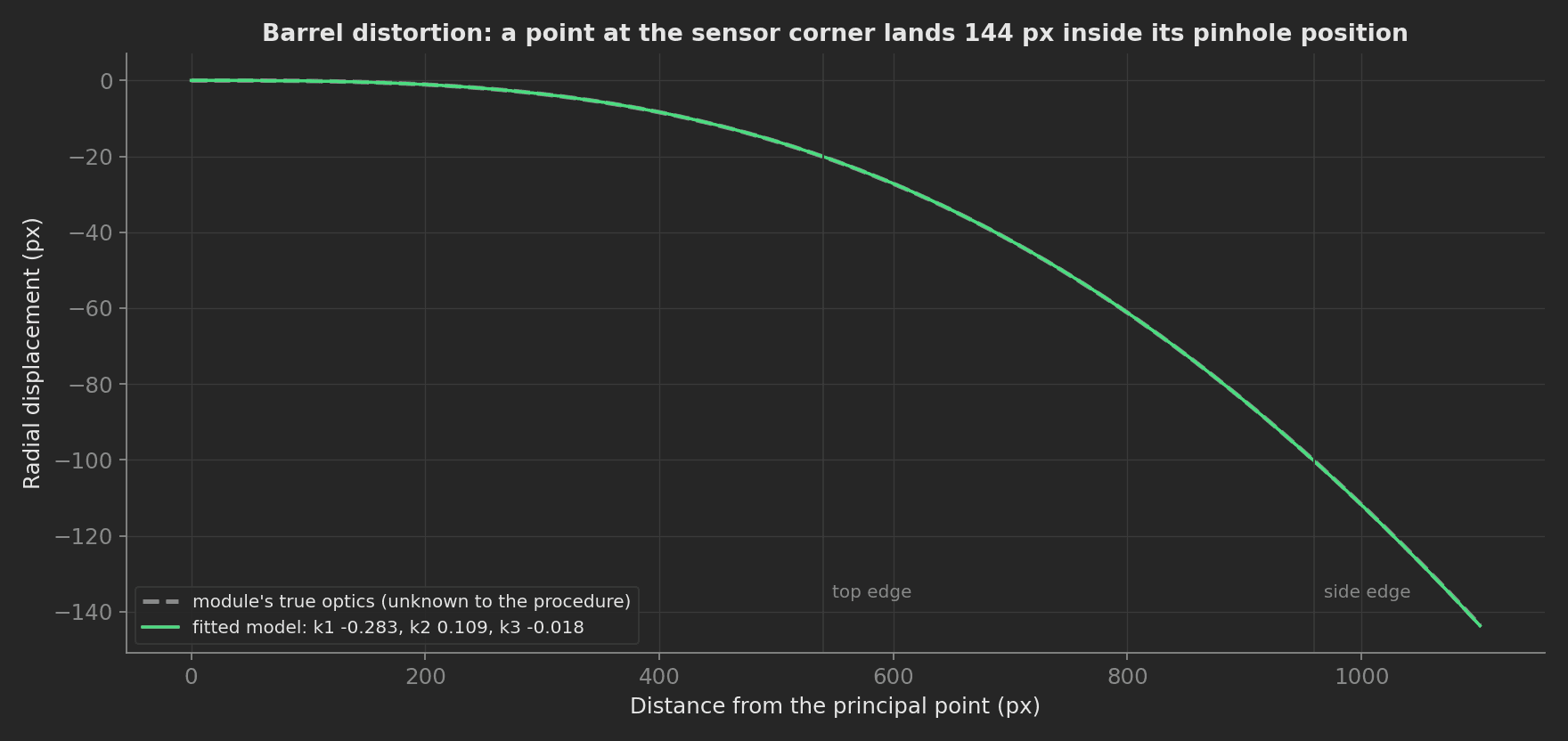
What the fit recovered against the optics the mock hides: fitted k1 −0.283 for a true −0.284, fx 1452.5 px for 1452.0, cx 963.4 for 963.5. At the sensor corner the barrel distortion moves a point 144 px inward; the fitted curve sits on top of the true one along the whole radius.
Verify on Held-Out Views
A fit can look good on its own data and still be wrong, especially with too few poses or poor coverage. The three held-out poses were captured but never given to the fit; their pose is solved with solvePnP from the calibrated model and their corners reprojected. The same phase undistorts each complete board row and measures how far it strays from a straight line, and derives the field of view from fx:
phases/verify_holdout.py35 lines
def verify_holdout(measurements, log): """Check the fitted model on poses the fit never saw, and that straight lines come out straight.""" with open("views.json") as f: holdout = json.load(f)["holdout"] with open("calibration.json") as f: cal = json.load(f) K = np.asarray(cal["camera_matrix"]) dist = np.asarray(cal["distortion"]) board = object_points() errors = [] straightness = [] for v in holdout: ids = np.asarray(v["ids"]) obj = board[ids].astype(np.float64) img = np.asarray(v["corners"], dtype=np.float64) ok, rvec, tvec = cv2.solvePnP(obj, img, K, dist) proj, _ = cv2.projectPoints(obj, rvec, tvec, K, dist) errors.append(float(np.sqrt(np.mean(np.sum((proj.reshape(-1, 2) - img) ** 2, axis=1))))) # undistort each complete board row and measure how far it strays from a straight line undist = cv2.undistortPoints(img.reshape(-1, 1, 2), K, dist, P=K).reshape(-1, 2) by_id = {int(i): p for i, p in zip(ids, undist)} for row in range(5): pts = [by_id[i] for i in row_ids(row) if i in by_id] if len(pts) == CORNERS_X: pts = np.asarray(pts) a, b = np.polyfit(pts[:, 0], pts[:, 1], 1) straightness.append(float(np.max(np.abs(pts[:, 1] - (a * pts[:, 0] + b))) / math.sqrt(1 + a * a))) hfov = math.degrees(2 * math.atan(IMAGE_SIZE[0] / (2 * K[0, 0]))) log.info(f"held-out RMS {max(errors):.3f} px over {len(holdout)} poses, straightness {max(straightness):.3f} px, HFOV {hfov:.1f} deg") measurements.holdout_rms_px = max(errors) measurements.line_straightness_px = max(straightness) measurements.hfov_deg = hfovOn the mock: held-out RMS 0.223 px, straightness 0.318 px, HFOV 66.9°. A model that overfits the calibration poses shows up here as a held-out error well above the fit RMS.
Write EEPROM
The coefficients are rounded to what the EEPROM format holds, written, read back, and compared as whole objects. The CRC of the payload becomes the calibration ID, on the run and on the unit:
def write_eeprom(measurements, unit, camera, log): """Write the coefficients to the module, read them back, compare byte for byte.""" with open("calibration.json") as f: cal = json.load(f) payload = { "model": cal["model"], "camera_matrix": [[round(x, 4) for x in row] for row in cal["camera_matrix"]], "distortion": [round(x, 6) for x in cal["distortion"]], } calibration_id = camera.write_calibration(payload) readback = camera.read_calibration() verified = readback == payload log.info(f"EEPROM {calibration_id}: {'verified' if verified else 'MISMATCH'}") measurements.eeprom_verified = verified measurements.calibration_id = calibration_id unit.metadata["calibration_id"] = calibration_idMock Plugs
The module mock hides a true model and answers capture(rvec, tvec) with the corner IDs inside the sensor and their projected positions plus 0.15 px of detector noise; the procedure never reads the true model. The stage mock generates the poses:
# The module's real optics, unknown to the procedure.K_TRUE = np.array([[1452.0, 0.0, 963.5], [0.0, 1449.0, 545.2], [0.0, 0.0, 1.0]])DIST_TRUE = np.array([-0.284, 0.112, 0.0006, -0.0004, -0.021]) # k1 k2 p1 p2 k3NOISE_PX = 0.15 def capture(self, rvec, tvec) -> dict: """Detections for the board at pose (rvec, tvec) in the camera frame. Positional args, plain lists.""" rvec = np.asarray(rvec, dtype=np.float64).reshape(3, 1) tvec = np.asarray(tvec, dtype=np.float64).reshape(3, 1) img_pts, _ = cv2.projectPoints(self._obj.astype(np.float64), rvec, tvec, K_TRUE, DIST_TRUE) img_pts = img_pts.reshape(-1, 2) + self._rng.normal(0.0, NOISE_PX, (len(self._obj), 2)) w, h = IMAGE_SIZE inside = (img_pts[:, 0] >= 8) & (img_pts[:, 0] <= w - 8) & (img_pts[:, 1] >= 8) & (img_pts[:, 1] <= h - 8) ids = np.nonzero(inside)[0] return {"ids": ids.tolist(), "corners": img_pts[ids].round(4).tolist()}Plug calls cross a JSON boundary, so rvec and tvec travel as plain lists and the detections come back as lists, not arrays. On a real station, capture() grabs a frame from the module and runs cv2.aruco.CharucoDetector on it, returning the same {ids, corners}; write_calibration and read_calibration become the module's I2C EEPROM transactions; the stage plug drives the real tilt and slide axes. The phases, the measurements and the limits do not change.