
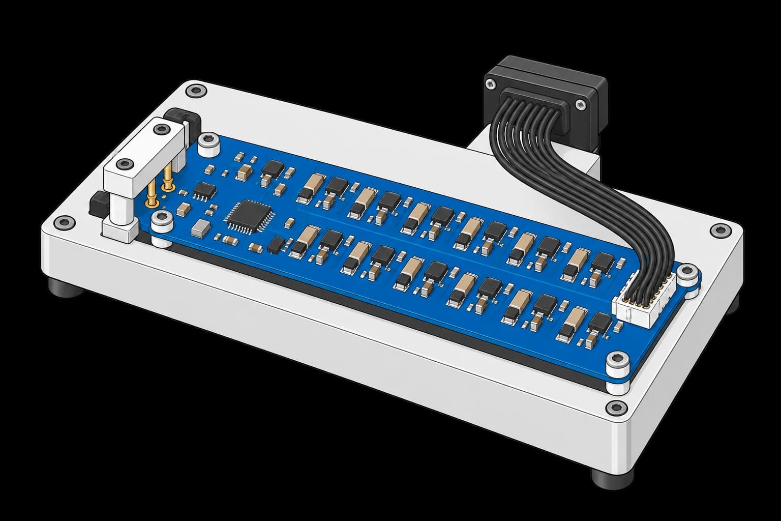
Get the complete source, dependencies and setup instructions from the template repository.
Open the source on GitHubIntroduction
Cell Balancing Overview
Cells in a series string drift apart. Passive balancing brings the high ones down: the AFE switches a bleed path across each cell, a resistor in series with a FET, and burns the excess charge as heat until the string is level again. On a 16S board that is sixteen bleed paths, each a resistor, a switch and a route back to the cell tap, and each one can be built wrong in a way no voltage-accuracy test sees: a resistor missing or of the wrong value, a FET open or, worse, stuck on, a command bit that lands on the wrong channel, firmware that never enables balancing at all. A stuck-on FET drains one cell in storage until the pack is over-discharged; a swapped channel balances the wrong cell for the life of the pack.
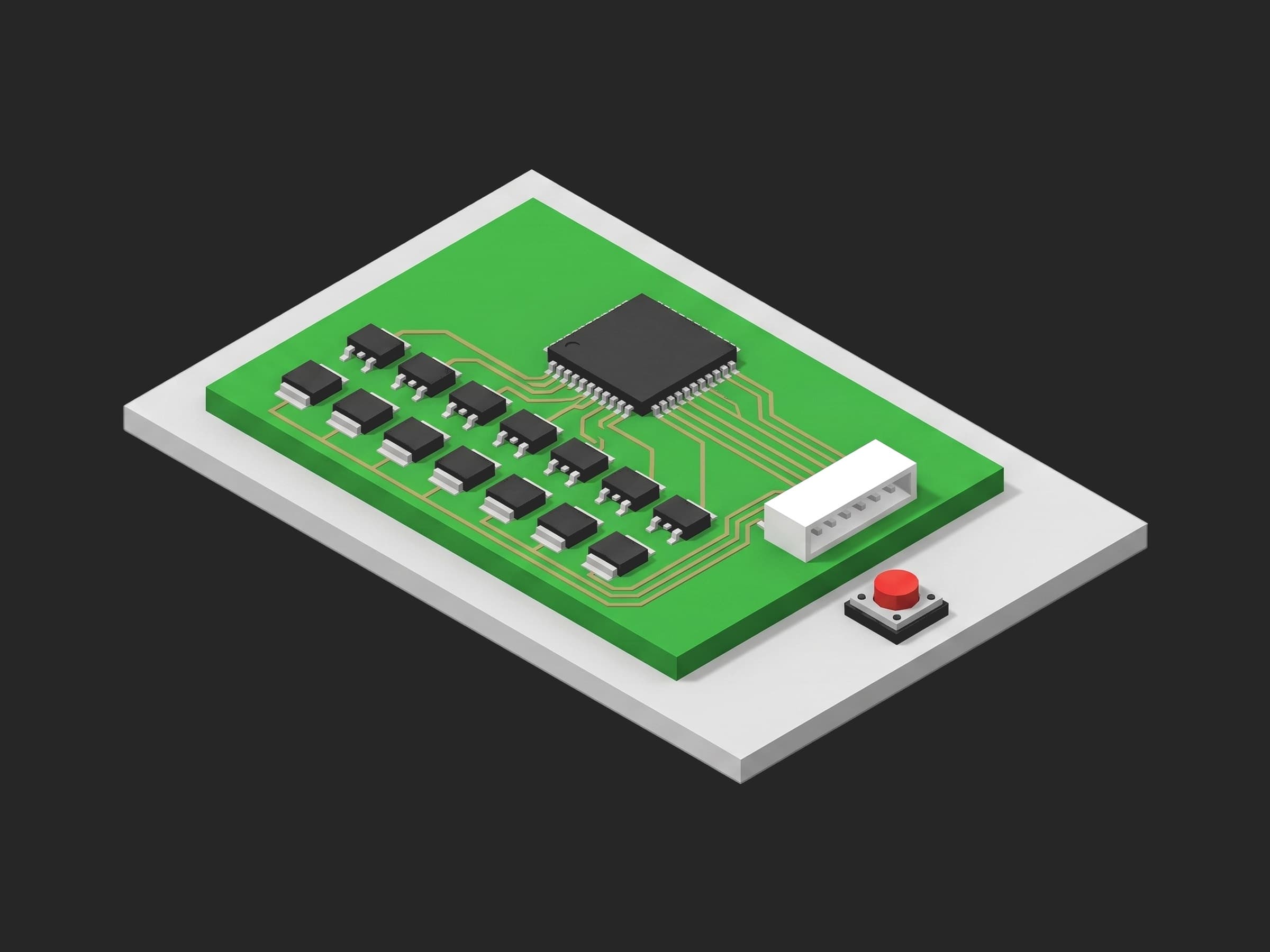
The bleed network of one board: a resistor and a discrete FET per channel, the AFE that switches them, and the copper back to the sense connector that every measurement in this template flows through.
Two vendor facts shape how the test has to be built. First, on an internal-balancing design there is no bleed resistor at all: the current flows through the cell input's own filter resistors and the AFE's on-die switch, and the BQ76952's internal balancing resistance is specified as 15 to 46 Ω across temperature (28 Ω typical) with 100 mA absolute maximum per cell (see the BQ76952 datasheet); an external-FET design like the one in this template adds a discrete bleed resistor and gets ~80 mA through it plus ~16 mA through the internal path, ~96 mA total at 4 V per TI SLUAA81A. Second, balancing is duty-cycled by the AFE: it is paused while the ADC scans the balanced cell and its neighbours, and for about 20 ms every second while the over- and under-voltage comparators are checked. A current read over a window shorter than that loop gives a number that depends on where the window landed.
Test Purpose
The procedure records one balancing fingerprint per board:
- Balancing configuration as one object: the enable bit, the minimum cell voltage, the minimum delta and the maximum simultaneous cells, the four registers that silently disable balancing when wrong
- Off-state leakage on every channel with balancing commanded off, on the simulator's 250 µA range
- Bleed current on every channel at 4.0 V, integrated over one second, odd channels in one pass and even channels in the next
- Command-to-channel attribution from two sources: current on the commanded ammeters and none on the others, and the firmware's own active-cell mask
- Balancing proven off at teardown
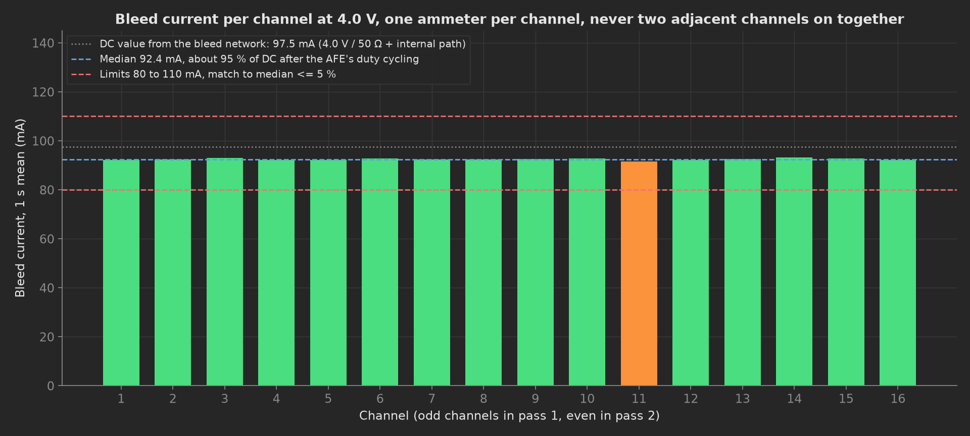
The mock board's sixteen bleed paths: every channel within 1 % of the median, all of them about 95 % of the DC value the resistor network predicts, which is the AFE's duty cycling and not a defect. Channel 11's resistor sits at the top of its tolerance and is the one to watch across a batch.
The framework mechanics on show are JSON == on the configuration that gates the test and on the firmware's active-cell list, a multi-dimensional measurement with an absolute pair and a relative aggregation on the same curve, a boolean built from two independent sources, a disabled phase for commissioning the station, and setup and teardown stages with a depends_on chain on one bench.
Equipment & Setup
To run this verification on a production line, the following are required:
- A battery cell simulator with one isolated, four-quadrant channel per cell input and a per-channel ammeter with a range for tens of milliamps and a range for microamps
- A service link to the DUT for the balancing command and the active-cell readback
- A pogo-pin fixture with Kelvin contacts on every cell-sense point
- The Device Under Test (DUT): a 16S BMS PCBA with its production firmware
- A TofuPilot Framework procedure to sequence the passes, integrate the currents and validate the limits
- The TofuPilot Dashboard to trend every channel's bleed current across boards
Hardware Components
Cell Simulator
The instrument is the ammeter. On a Chroma 87001 each of the 16 channels sources and sinks up to 5 A and reads its own current on four ranges: 0 to 9 A, 0 to 5 A at ±1 mA, 0 to 500 mA at ±100 µA for passive balancing, and 0 to 250 µA for the off-state quiescent current of the cell-supervision circuit. Those last two ranges exist for exactly this test; the datasheet says so. The Keysight SL1010A-803 adds per-channel charge integration (±50 µC over 50 ms), which is what a PWM-balanced design needs to avoid aliasing. A Pickering 41-752A can permit the balancing current but, on its simplified-sink variants, cannot measure it; its datasheet states the sink setting "may not represent precisely the current set by user".
The fixture exposes the board's repeated balancing networks and cell-sense connections. The isolated cell simulator and per-channel current measurements are external.
Why Not a Resistor Divider
A ladder of resistors across one supply is the cheap way to fake sixteen cells, and it cannot test balancing. The moment one channel bleeds, its current collapses that rung of the divider, the neighbouring inputs move, the over-voltage comparator trips, and the AFE disables balancing; TI states that "any time an over-voltage condition occurs, cell balancing is immediately disabled", and on some parts the event sets a permanent-fail bit. Sixteen isolated channels that can sink current are the price of entry.
The Registers That Disable Balancing
A dozen configuration conditions switch balancing off silently. On a BQ76952 the Cell Balance Min Cell V register defaults to 3900 mV, so a test that sets the simulator to 3.6 V commands sixteen channels and measures sixteen zeros; Cell Balance Min Delta defaults to a value that stops balancing when the cells are equal, which is precisely the condition of an accuracy test; the enable bit itself defaults off. The setup phase reads these four registers and validates them as one object before anything is commanded, and the pack goes to 4.0 V for the run.
Where the Limits Come From
No standard specifies a balancing test; ISO 26262 makes a stuck-on bleed FET a failure mode against the over-discharge safety goal, which is why automotive AFEs ship a built-in CBFET diagnostic, and says nothing about an end-of-line current. The limits derive from the bleed network and the AFE:
| Test | Limit | Basis |
|---|---|---|
| Off-state leakage | ≤ 30 µA per channel | AFE input bias 8 to 12 µA; a stuck FET reads 90 000 |
| Bleed current | 80 to 110 mA | 97.5 mA DC from 4.0 V / 50 Ω + internal path, minus the duty cycle, ±10 % for 1 % resistors and FET spread |
| Channel match | within 5 % of the median | channels on one die match far better than the absolute spec; a single bad channel shows here |
| Attribution | exact | no tolerance applies |
For an internal-balancing design the current limit must come from the AFE's min/max on-resistance, not its typical: 15 to 46 Ω on a BQ76952 puts the silicon spread alone at ±22 % around the typical value, and a ±10 % window fails good boards. The relative match limit is what makes the test sensitive either way.
Test Procedure
Overview
The procedure maps the verification onto the framework's three stages. The configuration gate lives in setup: so no channel is commanded on a board whose firmware would ignore the command. Switching everything off lives in teardown: so no board leaves the fixture with a bleed path on.
- Setup: balancing configuration as one object, pack to 4.0 V, all channels off.
- Main: off-state leakage on every channel, 250 µA range.
- Main: bleed current, odd pass then even pass, 1 s integration, attribution.
- Main (disabled by default): 50 ms versus 1 s window on one channel.
- Teardown: all off, proven off, cells parked.
Every metric validates against limits declared in procedure.yaml, and results stream to TofuPilot for per-channel trending.
Why TofuPilot Framework?
TofuPilot Framework is a YAML + Python test framework built for hardware manufacturing. Instead of writing all your test logic, measurements, and limits inside Python code, you describe what the test does in a procedure.yaml file, and how in small Python phase files. The framework handles:
- Automatic Python environment management (via
uv) - Operator UI (no frontend code needed)
- Measurement validation and live charts
- Process isolation between phases and equipment plugs
Project Structure
You can find the full source on GitHub. The BalanceBench plug is a mock of the simulator's channels and ammeters and the DUT's service port together, synthesizing a board with 1 % bleed resistors, healthy FETs and a correct command-to-channel map, so the procedure runs end-to-end without a simulator or a board connected.
tofupilot run .For CI or bench automation, the same run executes headless:
tofupilot run . --no-tui --no-kiosk --jsonThe Procedure File
procedure.yaml declares the unit, the bench plug with its cell count as constructor argument, and the three stages with every measurement and limit:
procedure.yaml128 lines
name: BMS Cell Balancing Verificationversion: 0.1.0description: Passive balancing verification of a 16S BMS PCBA on a cell simulator. Balancing configuration read first, off-state leakage per channel on the 250 uA range, bleed current per channel in odd and even passes with command-to-channel attribution, currents integrated over 1 s against the AFE duty cycle.unit: auto_identify: true serial_number: description: "Scan the board data-matrix before it goes into the fixture" placeholder: "BMS16-00000" pattern: "^BMS16-\\d{5}$" default_value: "BMS16-01744" part_number: default_value: "PCB-BMS-16S-R3" batch_number: default_value: "LOT-2026-37"plugs: - name: Balance Bench description: "16-channel cell simulator with per-channel ammeters and DUT UART (mock Chroma 87001-class, one plug per bench)" python: plugs.balance_bench:BalanceBench key: bench config: cell_count: 16setup: - name: Balance Gate key: balance_gate python: phases.balance_gate measurements: - name: Balance Config key: balance_config description: "The four registers that silently disable balancing: enable bit, minimum cell voltage, minimum delta, maximum simultaneous cells." validators: - operator: "==" expected_value: cb_enabled: true min_cell_mv: 3900 min_delta_mv: 0 max_cells: 8main: - name: Off State Leakage key: off_state_leakage python: phases.off_state_leakage measurements: - name: Off Leakage key: off_leakage title: Channel current with balancing commanded off, 250 µA range x_axis: legend: Channel y_axis: - legend: Leakage key: leak unit: µA aggregations: - type: max_ua unit: µA validators: - {operator: "<=", expected_value: 30.0} - name: Active Cells Off key: active_cells_off description: Firmware's own view of which channels balance; must be empty here. validators: - operator: "==" expected_value: [] - name: Bleed Current key: bleed_current python: phases.bleed_current depends_on: [off_state_leakage] timeout: 2m measurements: - name: Bleed key: bleed title: Bleed current per channel at 4.0 V, odd then even, 1 s integration x_axis: legend: Channel y_axis: - legend: Current key: current unit: mA aggregations: - type: min_ma unit: mA validators: - {operator: ">=", expected_value: 80.0} - type: max_ma unit: mA validators: - {operator: "<=", expected_value: 110.0} - type: match_pct unit: "%" validators: - {operator: "<=", expected_value: 5.0} - name: Attribution key: attribution_ok description: Every commanded channel and no other sourced current, and the firmware's active-cell mask agreed; a swapped bleed path or a wrong bitmap breaks it. validators: - {operator: "==", expected_value: true} - name: Duty Cycle Check key: duty_cycle_check python: phases.duty_cycle_check enabled: false depends_on: [bleed_current] measurements: - name: Short Window Spread key: short_window_spread_ma unit: mA - name: Long Window key: long_window_ma unit: mAteardown: - name: Balancing Off key: balancing_off python: phases.balancing_off measurements: - name: Active Cells After key: active_cells_after validators: - operator: "==" expected_value: [] - name: Max Leak After key: max_leak_after_ua unit: µA validators: - {operator: "<=", expected_value: 30.0}Framework features to notice:
- The gate is a configuration object.
balance_configvalidates four registers with one==before the first channel is commanded; a board withcb_enabled: falsefails in setup with the reason, not in main with sixteen zeros. - An off-state measurement with a limit.
off_leakageis a multi-dimensional measurement with one aggregation,max_ua <= 30; it is the phase that finds a stuck-on FET. - Absolute and relative on one curve.
bleedcarriesmin_maandmax_mafrom the network's DC value, andmatch_pctagainst the median; the third is the sensitive one. - Empty-list equality.
active_cells_off == []andactive_cells_after == []validate the firmware's own active-cell mask as a JSON value. enabled: false. The duty-cycle check ships disabled; it runs once when the station's integration time is set.
Balance Gate
The setup phase reads the balancing configuration, brings the pack to 4.0 V (above the 3900 mV minimum cell voltage below which nothing balances), commands every channel off, and stamps the test voltage onto the unit metadata:
from utils.recipe import CELL_COUNT, TEST_MVdef balance_gate(measurements, bench, unit, log): """Setup: the configuration that silently disables balancing, read before anything is commanded. Min Cell V defaults to 3900 mV on a BQ76952: a test at 3.6 V would command sixteen channels and measure sixteen zeros. The pack goes to 4.0 V for the whole run.""" cfg = bench.dut_balance_config() measurements.balance_config = cfg bench.set_all_cells_mv(TEST_MV) bench.dut_set_balancing([]) unit.metadata["balance_test_mv"] = TEST_MV log.info(f"Board {unit.serial_number}: balancing enabled, min cell {cfg['min_cell_mv']} mV, {CELL_COUNT} channels at {TEST_MV} mV")Off State Leakage
Every channel commanded off, every ammeter on the 250 µA range. A healthy input draws the AFE's bias current, 8 to 12 µA on a BQ79616-class part; a bleed FET stuck on draws the full bleed current, three decades above the limit. The phase records the firmware's active-cell mask alongside, which must be empty:
import numpy as npfrom utils.recipe import CELL_COUNTdef off_state_leakage(measurements, bench, log): """Every channel with balancing commanded OFF, current on the 250 uA range. A stuck-on bleed FET reads tens of milliamps here and nowhere else; half the defect coverage of this template is this one phase.""" bench.dut_set_balancing([]) leak = np.array([bench.sim_channel_leak_ua(ch) for ch in range(1, CELL_COUNT + 1)]) measurements.off_leakage.x_axis = list(range(1, CELL_COUNT + 1)) measurements.off_leakage.y_axis.leak = leak.tolist() measurements.off_leakage.y_axis.leak.aggregations.max_ua = float(leak.max()) measurements.active_cells_off = bench.dut_active_cells() log.info(f"Off-state leakage {leak.min():.1f}..{leak.max():.1f} uA, firmware reports active cells {bench.dut_active_cells()}")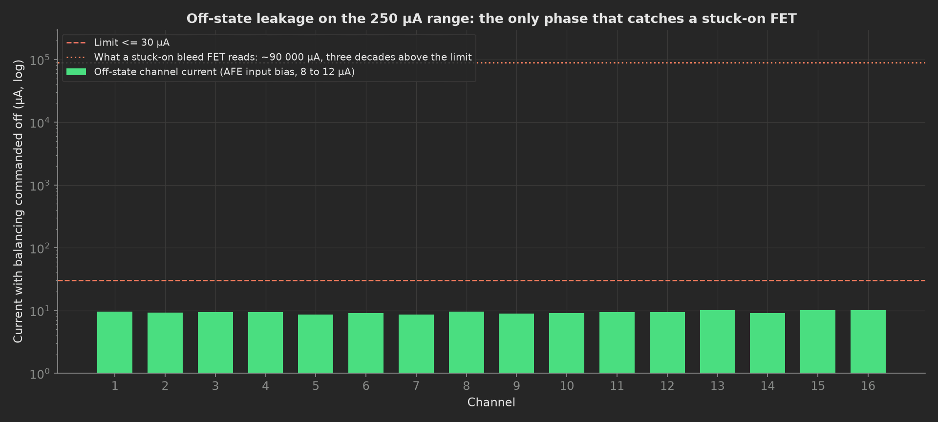
The mock's sixteen off-state currents on a log axis, with the stuck-FET signature three decades above. A test that only measures the on state cannot see this defect, and it is the one with field consequences.
Bleed Current
Two passes, odd channels then even channels. Turning all sixteen on at once is not an option: on the bq769x0 family TI states the part "is likely to be damaged" when every cell in a group balances together, and the BQ79616 refuses more than two consecutive FETs; the vendor's own diagnostic sequence is odd/even. Non-adjacent grouping keeps per-channel attribution, because each channel has its own ammeter, and cuts the passes from sixteen to two. Each current is integrated over one second so the AFE's duty cycling averages out. The phase checks, in both passes, that every commanded channel sources current, that no other channel does, and that the firmware's active-cell mask matches the command:
phases/bleed_current.py35 lines
import numpy as npfrom utils.recipe import CELL_COUNT, EXPECTED_MA, INTEGRATION_S, PASSESdef bleed_current(measurements, bench, log): """Bleed current per channel in two passes, odd then even, never two adjacent channels at once. Each channel has its own ammeter, so the grouping keeps per-channel attribution: a command bit routed to the wrong channel shows as current on the wrong ammeter.""" current = np.zeros(CELL_COUNT) attribution_ok = True for group in PASSES: bench.dut_set_balancing(group) if sorted(bench.dut_active_cells()) != sorted(group): attribution_ok = False for ch in range(1, CELL_COUNT + 1): i_ma = bench.sim_channel_current_ma(ch, INTEGRATION_S) if ch in group: current[ch - 1] = i_ma elif i_ma > 1.0: # Current on a channel that was not commanded: a swap. attribution_ok = False log.warning(f"Channel {ch} sources {i_ma:.1f} mA while not commanded") bench.dut_set_balancing([]) median = float(np.median(current)) measurements.bleed.x_axis = list(range(1, CELL_COUNT + 1)) measurements.bleed.y_axis.current = current.tolist() measurements.bleed.y_axis.current.aggregations.min_ma = float(current.min()) measurements.bleed.y_axis.current.aggregations.max_ma = float(current.max()) measurements.bleed.y_axis.current.aggregations.match_pct = float(100.0 * (np.abs(current - median) / median).max()) measurements.attribution_ok = attribution_ok worst = int(np.abs(current - median).argmax()) + 1 log.info(f"Bleed {current.min():.1f}..{current.max():.1f} mA against {EXPECTED_MA:.1f} mA expected, median {median:.1f}, worst match channel {worst}, attribution {'ok' if attribution_ok else 'BROKEN'}")The swap case is the argument for this structure. Commanding all channels and measuring the total current gives the same number whether cell 5's command bit drives cell 5 or cell 6; the AFE's built-in CBFET diagnostic cannot see it either, because the IC's view of "cell 5" is self-consistent whatever the PCB routed there. Only an external ammeter that knows the physical channel catches it.
Duty Cycle Check
Disabled by default. It reads one channel ten times with a 50 ms window and once with the 1 s window, and reports the spread of the short readings. Run it when the station's integration time is chosen, not on every board.
from utils.recipe import INTEGRATION_Sdef duty_cycle_check(measurements, bench, log): """Disabled by default. Reads one channel with a 50 ms window and with the 1 s window to show how much the AFE's duty-cycling moves a short reading; run it when the integration time of the station is set.""" bench.dut_set_balancing([1]) short = [bench.sim_channel_current_ma(1, 0.05) for _ in range(10)] long = bench.sim_channel_current_ma(1, INTEGRATION_S) bench.dut_set_balancing([]) spread = max(short) - min(short) measurements.short_window_spread_ma = float(spread) measurements.long_window_ma = long log.info(f"50 ms windows spread {spread:.1f} mA on channel 1; 1 s window {long:.1f} mA")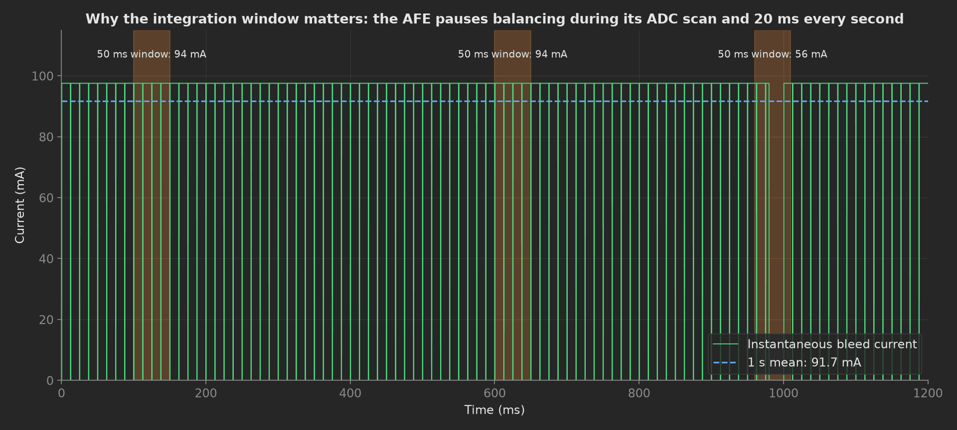
Why the window is one second: the AFE suspends balancing for each ADC scan of the balanced cell and its neighbours, and for about 20 ms every second while it checks the over- and under-voltage comparators. Two 50 ms windows read 94 mA; the one that lands on the comparator pause reads 56 mA. Both are the same healthy channel. A limit derived from the DC equation and applied to a short reading produces a "flaky" balancing test that fails good boards.
Balancing Off
The teardown phase commands every channel off, reads the firmware's mask and the worst off-state current again, and parks the cells at 3.6 V:
from utils.recipe import CELL_COUNTdef balancing_off(measurements, bench, log): """Teardown: every bleed path off and proven off, cells back to 3.6 V.""" bench.dut_set_balancing([]) measurements.active_cells_after = bench.dut_active_cells() measurements.max_leak_after_ua = max(bench.sim_channel_leak_ua(ch) for ch in range(1, CELL_COUNT + 1)) bench.set_all_cells_mv(3600) log.info(f"Balancing off, active cells {bench.dut_active_cells()}, cells parked at 3600 mV")Mock Plug
BalanceBench stands in for the simulator's channels and ammeters and the DUT's service port because the ammeters read what the DUT switches, and plugs run in separate processes. Its bleed resistors are 50 Ω ± 0.4 %, channel 11's at +0.9 %; the internal path is 2 × 100 Ω of filter plus a 28 Ω on-die switch with 8 % spread; the FETs add 50 mΩ; the off-state current is the AFE's 9.5 µA input bias, and a channel commanded on while it should be off would add 90 mA to it. A current read over one second is 95 % of the DC value, the mock's stand-in for the duty cycling; a 50 ms read scatters by ±8 %. The command-to-channel map is the identity. Every method returns plain Python types because plug calls cross a JSON boundary; a measurement read back from measurements.<key> returns a proxy, so the phases keep locals for their log lines.
On a real bench, the class speaks SCPI to the simulator (MEAS:CURR per channel with the range selected explicitly, 500 mA on and 250 µA off) and pyserial to the DUT for the balancing command and the CB_ACTIVE_CELLS readback. Integrate over at least one second or slow the AFE's cell-balance loop, keep balancing off during any voltage-accuracy phase (eight balancing cells bias the top cell reading by 5 mV through 20 Ω filters), and for an active-balancing design measure the cell-side current and its direction, not the efficiency, which is a characterization measurement. The phases, measurements and limits stay the same.