
Get the complete source, dependencies and setup instructions from the template repository.
Open the source on GitHubIntroduction
Cold Plate Qualification Overview
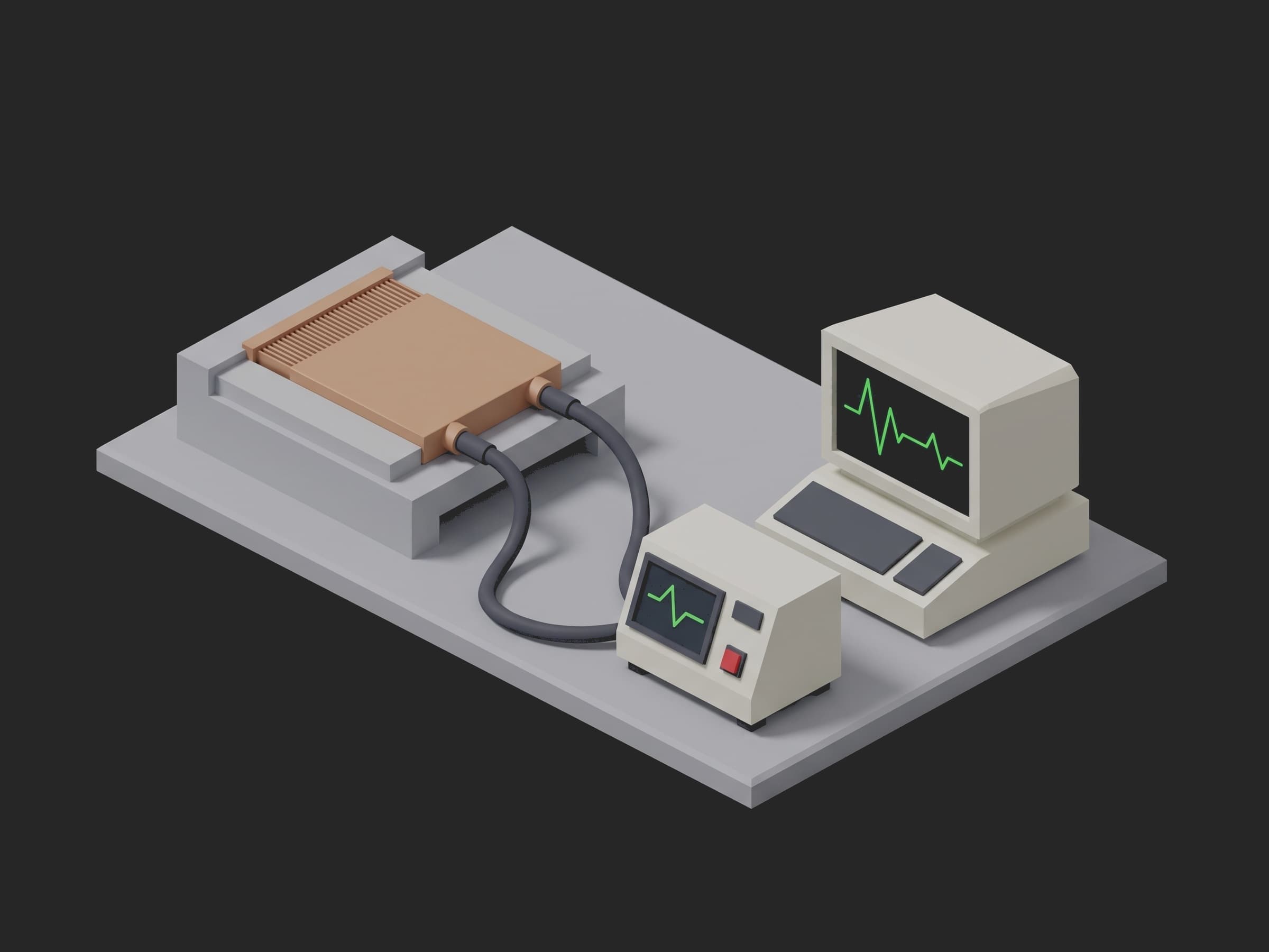
A direct-to-chip liquid-cooled server has no fan moving the heat off its accelerators. A copper cold plate sits on each 1 kW class GPU or CPU through a thermal interface, coolant enters through one quick-disconnect stub, passes a field of microchannel fins a few hundred micrometres wide, and leaves through the other stub about 10 K warmer. Dozens of these plates hang in series and parallel off a tray manifold, the tray off a rack manifold, the rack off a coolant distribution unit, and the whole secondary loop runs PG25, a 25 % propylene glycol water mix with a corrosion inhibitor package. One plate that ships out of spec is not one warm chip: it is a weep at a lid braze that puts glycol on a 10 kW board, a blocked channel that throttles one accelerator in a training job of a thousand, a burr of brazing flux that lodges in the next plate's fins, or a plate shipped wet that freezes in the container.
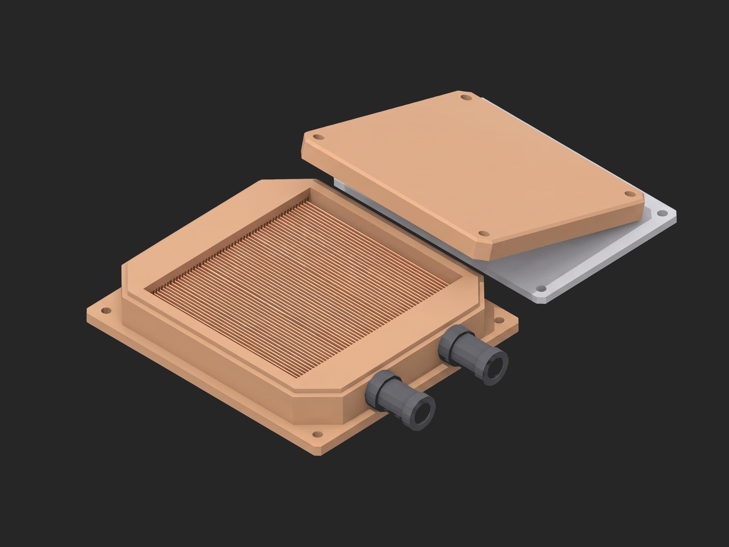
The parts this test exercises: the two quick-disconnect stubs and their seals, the lid-to-body braze or weld that holds the maximum operating pressure, the fin field that sets the thermal resistance and the pressure drop, and whatever the machining and brazing left inside it.
The OCP Cold Plate Development and Qualification white paper gives a production test writer most of the numbers. Leak tightness is a pressure decay under 0.5 % over the hold (the EN 1779 pressure-change method); burst margin is a hydrostatic dwell at 1x the maximum operating pressure for 5 min then 3x for 2 min, quoted from IEC 62368-1; thermal performance is R = (Tcase - Tinlet) / P measured at several flows; pressure drop is the loop with the plate minus the same loop through a bypass, so hoses and quick-disconnects do not end up in the plate's number; cleanliness is no particle above 50 um after the flush; and the coolant velocity stays under 1.5 m/s so the copper does not erode. The OCP ACS cold plate requirements set the interfaces, the OCP Liquid Cooling Integration and Logistics white paper puts a gaseous leak test at L10 before any coolant enters a server, and the Catalina compute tray specification fixes the rack boundary this plate lives in: 40 C supply, 1.25 to 1.5 LPM/kW, 15 psi across the rack loop. Every limit in this template is one of those numbers, or says where it came from instead.
Test Purpose
The procedure records one qualification fingerprint per plate:
- Coolant conductivity and supply temperature of the bench loop, stamped on the run as metadata, the conductivity also judged, and the dry tare mass of the plate
- Dry N2 pressure decay at the maximum operating pressure, the whole 96 s trace, judged on the decay over the 60 s hold, with one retry for a stub not fully seated
- Hydrostatic at 1x MOP for 5 min then 3x for 2 min with the pump isolated, the trace whole, judged on the minimum of each dwell, and the operator's deformation check as a switch bound to a measurement
- Pressure drop at six flows around the design flow, the loop, the bypass and the difference, judged at the design flow only, with the velocity in the stubs
- Thermal resistance at four power steps to 1 kW at the design flow, case and inlet temperature and R at each, with the energy balance closed at the outlet
- Particle counts per size bin after a 10 min flush, judged on the bin above 50 um, and the inline filter's dP settled
- The residual coolant after the blow-down against the dry tare, the caps confirmed, and the raw pressure log attached to the run
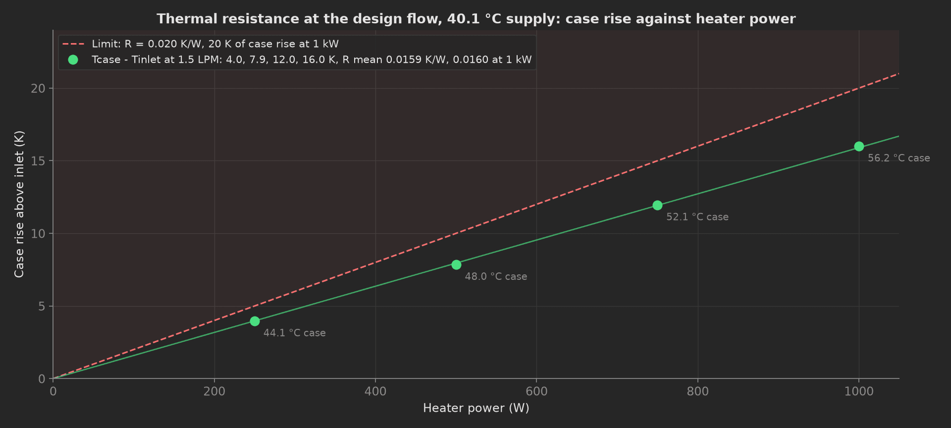
The mock plate's thermal curve: 16.0 K of case rise at 1 kW on a 40.1 C supply, 0.016 K/W, against a limit that allows 20 K. A plate with one channel blocked by flux runs the same line steeper and closes the heat balance short.
The framework mechanics on show are then: {fail: retry} with a retry limit of one on the pressure decay, so the common false fail gets a second seating before the run stops; an operator switch bound to a boolean measurement with bind:; run.metadata for the bench's coolant state; previous-results injection, the teardown reading the dry tare from the identify phase by naming it as a parameter; attach.data for the raw pressure log; and multi-dimensional measurements where the loop and the bypass curves are recorded next to the plate curve that is judged.
Equipment & Setup
To run this qualification on a production line, the following are required:
- A dry N2 supply with a regulator and a pressure transducer resolving 0.01 kPa at 300 kPa gauge, for the decay
- A fill and hydrostatic pump reaching 3x the plate's MOP with an isolation valve, so the dwells are held by the plate and not by the pump
- A flow loop with a flow meter, a bypass valve, two differential pressure cells and a recirculating chiller holding a 40 C PG25 supply
- A heater block with a PID controller to 1 kW, a class A RTD in its pedestal for the case temperature, and inlet and outlet RTDs in the loop
- An inline 50 um filter with its own dP cell and a liquid particle counter on the effluent
- A conductivity probe in the loop and a scale under the fixture resolving 0.1 g at 1 kg
- The Device Under Test (DUT): a copper microchannel cold plate for a 1 kW class device with two quick-disconnect stubs, dry, as it leaves brazing and machining
- A TofuPilot Framework procedure to sequence the stimuli and validate the limits
- The TofuPilot Dashboard to keep the per-plate evidence and the pressure logs a customer's incoming inspection will ask for
Hardware Components
Flow Loop, Pressure Cells and Chiller
The plate's own pressure drop is a subtraction, so the two differential pressure cells matter more than the flow meter: an Endress+Hauser Deltabar or an equivalent wet-wet dP cell spanning 0 to 50 kPa across the plate and across the bypass, with the same tapping points, and a Coriolis or ultrasonic flow meter from Bronkhorst or Keyence resolving 0.005 LPM at 1.5. The chiller has to hold the supply within 0.1 K through a 1 kW step, which is a Julabo or Huber recirculator sized well above the heater, not a bench chiller at its limit. The N2 side is a regulator, a solenoid, and a transducer good to 0.01 kPa; the hydrostatic side is a small piston or diaphragm pump reaching 1 MPa and a valve to isolate it.
A single-fixture station: the plate clamped on the heater block with its two stubs mated to the bench's quick-disconnects, the pump, the N2 and the loop in one enclosure beside it, the scale under the fixture.
Heater Block, Particle Counter and Scale
The heater block stands in for the accelerator: a copper pedestal with cartridge heaters driven by a Watlow controller, a class A RTD in a hole a millimetre under the contact face, and the same thermal interface material the product will use. The case temperature is measured there and nowhere else, so every R this bench reports carries the same interface. The particle counter is a light-extinction instrument on the flush effluent, a PAMAS S40 or a Beckman Coulter HIAC class, reporting counts per 100 mL in size bins; the inline filter ahead of the counter is the 50 um element the rack's CDU would carry anyway, with a dP cell across it. The scale is a Mettler Toledo precision balance under the fixture, tared once per plate before the stubs go on and read again after the blow-down. The quick-disconnects on the bench side are the rack's, Amphenol UQD, Parker or CPC depending on the program, so a stub that seals here seals in the tray.
Where the Limits Come From
| Test | Limit | Basis |
|---|---|---|
| Coolant conductivity | 3000 to 6000 uS/cm | inhibited PG25 reads about 4700 uS/cm at 20 C on supplier data sheets, and the OCP PG25 base spec limits the blend water to 25 uS/cm; the window is this line's |
| Dry mass | 695 to 745 g | the plate's drawing, 720 g nominal |
| Pressure decay | under 0.5 % over the 60 s hold, from at least 285 kPa | OCP cold plate qualification (EN 1779 method) |
| Hydrostatic | min 285 kPa over the 1x dwell (5 min), min 855 kPa over the 3x dwell (2 min) | IEC 62368-1 as OCP quotes it for the pressures and times; the 5 % floor is this line's |
| Deformation | none visible | OCP hydrostatic acceptance |
| Pressure drop | at or under 15 kPa across the plate at 1.5 LPM | OCP for the loop-minus-bypass method and the Catalina rack boundary for 1.5 LPM/kW; the 15 kPa is this line's budget, two plates in series and the tray manifold inside the rack's 15 psi |
| Stub velocity | at or under 1.5 m/s | OCP erosion-corrosion limit for copper |
| Thermal resistance | mean and full-power R at or under 0.020 K/W, case at or under 60 C, inlet 38 to 42 C | OCP for R = (Tcase - Tinlet) / P; 0.020 K/W is this line's derivation, a 60 C case ceiling on the Catalina 40 C supply |
| Heat balance | 90 to 110 % at 1 kW | this line's, closing the energy balance at the outlet RTD |
| Particulate | zero counts above 50 um, filter dP risen less than 0.2 kPa | OCP for the 50 um rule; the filter criterion is this line's |
| Residual coolant | at or under 3.0 g | this line's shipping limit, about 10 % of the 28 mL fill |
Two rows in that table are traps. The decay percentage depends on when the hold starts: gas compressed into a cold plate warms, then cools back over tens of seconds, and a hold that starts too early reads a thermal transient as a leak. The procedure waits 30 s after the ramp and judges the next 60 s, and the chart shows both windows. And the thermal resistance depends on the interface as much as on the plate, so the bench uses the product's own TIM and the same pedestal for every plate; a number from a different interface is a different measurement.
Test Procedure
Overview
The procedure maps the qualification onto the framework's three stages. The tare and the coolant state live in setup: with the N2 decay chained after them, so the plate is weighed dry before the stubs go on and no coolant enters a plate that leaks gas. The drain, the blow-down and the residual live in teardown: so a plate goes back on the scale dry even when a main phase fails.
- Setup: dry tare on the scale, coolant conductivity and supply temperature on the run.
- Setup: dry N2 to 300 kPa, 30 s stabilise, 60 s hold, one retry.
- Main: fill with PG25, 300 kPa for 5 min then 900 kPa for 2 min, deformation switch.
- Main: six flows from 0.75 to 2.0 LPM, loop and bypass dP, plate dP and stub velocity.
- Main: 250 to 1000 W at 1.5 LPM, R at each step, heat balance at 1 kW.
- Main: 10 min flush at 3 LPM, particle counts per bin, filter dP settled.
- Teardown: drain, blow-down, caps, residual against the tare, pressure log attached.
Every metric validates against limits declared in procedure.yaml, and results stream to TofuPilot as the per-plate evidence.
Why TofuPilot Framework?
TofuPilot Framework is a YAML + Python test framework built for hardware manufacturing. Instead of writing all your test logic, measurements, and limits inside Python code, you describe what the test does in a procedure.yaml file, and how in small Python phase files. The framework handles:
- Automatic Python environment management (via
uv) - Operator UI (no frontend code needed)
- Measurement validation and live charts
- Process isolation between phases and equipment plugs
Project Structure
You can find the full source on GitHub. The ColdPlateBench plug is a mock of the N2 supply, the pump, the flow loop with its dP cells, the heater block with its RTDs, the filter, the particle counter, the conductivity probe and the scale together, synthesizing a healthy plate that decays 0.08 % over the hold, drops 9.96 kPa at 1.5 LPM and runs 0.016 K/W at 1 kW, so the procedure runs end-to-end without a bench or a plate connected.
tofupilot run .For CI or bench automation, the same run executes headless, with the deformation switch answered from ui.json:
tofupilot run . --no-tui --no-kiosk --json --ui-values ui.json --ui-timeout 60The Procedure File
procedure.yaml declares the unit, the bench plug with the label serial as constructor argument, and the three stages with every measurement and limit:
procedure.yaml236 lines
name: Cold Plate Leak and Thermal Qualificationversion: 0.1.0description: Qualification of a direct-to-chip liquid cold plate for a 1 kW class GPU or CPU, OCP ACS style, PG25 coolant. Coolant conductivity and supply temperature on the run, dry N2 pressure decay before any coolant with one retry for a QD not seated, hydrostatic at 1x then 3x the maximum operating pressure with the operator's deformation check bound to a switch, the plate's own pressure drop as loop minus bypass across a flow sweep, thermal resistance at four power steps with the energy balance closed at the outlet, a flush judged on nothing above 50 um, and a teardown that drains, caps, weighs the residual against the dry tare and attaches the raw pressure log.unit: auto_identify: true serial_number: description: "Scan the laser mark on the plate's lid" placeholder: "CP-1K-000000" pattern: "^CP-1K-\\d{6}$" default_value: "CP-1K-003118" part_number: default_value: "CP-1K-CU-QD6" batch_number: default_value: "LOT-2026-38"plugs: - name: Cold Plate Bench description: "N2 supply, fill and hydrostatic pump, flow loop with bypass and two dP cells, heater block with RTDs, inline filter and particle counter, conductivity probe and scale (mock, one plug per bench)" python: plugs.cold_plate_bench:ColdPlateBench key: bench config: serial_number: "CP-1K-003118"setup: - name: Identify key: identify python: phases.identify measurements: - name: Coolant Conductivity key: coolant_conductivity_us_cm unit: µS/cm description: "The bench loop's PG25, at the conductivity probe. Inhibited PG25 reads about 4700 uS/cm (supplier data sheets); a low reading is a loop topped up with water, a high one is contamination. The window is this line's." validators: - {operator: ">=", expected_value: 3000.0} - {operator: "<=", expected_value: 6000.0} - name: Dry Mass key: dry_mass_g unit: g description: "Dry tare on the scale before anything is connected, 720 g nominal. A plate outside the window is missing a fin field or carries the wrong lid; the teardown subtracts this from the wet mass." validators: - {operator: ">=", expected_value: 695.0} - {operator: "<=", expected_value: 745.0} - name: Dry Pressure Decay key: dry_pressure_decay python: phases.dry_pressure_decay depends_on: [identify] retry: limit: 1 then: fail: retry measurements: - name: Pressure Decay key: pressure_decay title: Dry N2 at the maximum operating pressure, 30 s stabilise, 60 s hold x_axis: legend: Time unit: s y_axis: - legend: Pressure key: pressure unit: kPa aggregations: - type: hold_start_kpa unit: kPa validators: - {operator: ">=", expected_value: 285.0} - type: decay_pct unit: "%" validators: - {operator: "<=", expected_value: 0.5}main: - name: Hydrostatic key: hydrostatic python: phases.hydrostatic ui: components: - key: deformation_check type: switch label: "No visible deformation after the 3x dwell" description: "Lid flat under the straightedge, no bulge over the fin field, no weep at the stubs or the lid seam" required: true bind: measurements.no_deformation measurements: - name: Hydrostatic Pressure key: hydrostatic title: Filled with PG25, 1x MOP for 5 min then 3x MOP for 2 min, pump isolated during each dwell x_axis: legend: Time unit: s y_axis: - legend: Pressure key: pressure unit: kPa aggregations: - type: min_1x_dwell_kpa unit: kPa validators: - {operator: ">=", expected_value: 285.0} - type: min_3x_dwell_kpa unit: kPa validators: - {operator: ">=", expected_value: 855.0} - name: No Deformation key: no_deformation description: "The operator's inspection after the 3x dwell, recorded through the switch bound to this measurement." validators: - {operator: "==", expected_value: true} - name: Flow and Pressure Drop key: flow_pressure_drop python: phases.flow_pressure_drop depends_on: [hydrostatic] measurements: - name: Flow Curve key: flow_curve title: Pressure drop across the plate as loop minus bypass, six flows around 1.5 LPM x_axis: legend: Flow unit: LPM y_axis: - legend: Plate dP (loop minus bypass) key: plate_dp unit: kPa aggregations: - type: at_design_flow_kpa unit: kPa validators: - {operator: "<=", expected_value: 15.0} - legend: Loop dP with plate key: loop_dp unit: kPa - legend: Bypass dP key: bypass_dp unit: kPa - legend: Velocity in the QD stubs key: stub_velocity unit: m/s aggregations: - type: at_design_flow_m_s unit: m/s validators: - {operator: "<=", expected_value: 1.5} - name: Thermal Resistance key: thermal_resistance python: phases.thermal_resistance depends_on: [flow_pressure_drop] timeout: 20m measurements: - name: Thermal Curve key: thermal_curve title: Case and inlet temperature and R = (Tcase - Tinlet) / P at four power steps, 1.5 LPM, 40 C supply x_axis: legend: Heater power unit: W y_axis: - legend: Case temperature key: tcase_c unit: °C aggregations: - type: max_c unit: °C validators: - {operator: "<=", expected_value: 60.0} - legend: Inlet temperature key: tin_c unit: °C aggregations: - type: mean_c unit: °C validators: - {operator: ">=", expected_value: 38.0} - {operator: "<=", expected_value: 42.0} - legend: Thermal resistance key: r_k_per_w unit: K/W aggregations: - type: mean_k_per_w unit: K/W validators: - {operator: "<=", expected_value: 0.020} - type: at_full_power_k_per_w unit: K/W validators: - {operator: "<=", expected_value: 0.020} - name: Coolant Heat Balance key: coolant_heat_balance_pct unit: "%" description: "Heat carried away by the coolant (mass flow, cp, outlet minus inlet) as a share of the heater power at 1 kW. Below 90 % a channel is blocked or the case RTD sits on a hot spot; above 110 % the flow meter or an RTD is wrong." validators: - {operator: ">=", expected_value: 90.0} - {operator: "<=", expected_value: 110.0} - name: Particulate Flush key: particulate_flush python: phases.particulate_flush depends_on: [thermal_resistance] timeout: 20m measurements: - name: Particle Counts key: particle_counts title: Effluent particle counts per 100 mL by size bin after a 10 min flush at 3 LPM x_axis: legend: Size bin lower edge unit: µm y_axis: - legend: Count per 100 mL key: count aggregations: - type: over_50um validators: - {operator: "==", expected_value: 0} - name: Filter dP Stable key: filter_dp_stable description: "The inline 50 um filter's dP rose by less than 0.2 kPa over the flush, so the plate had stopped shedding when the flush ended." validators: - {operator: "==", expected_value: true}teardown: - name: Drain and Cap key: drain_and_cap python: phases.drain_and_cap measurements: - name: Residual Coolant key: residual_coolant_g unit: g description: "Wet mass after the N2 blow-down minus the dry tare from identify. About 10 % of the 28 mL fill is this line's shipping limit for a plate shipped drained." validators: - {operator: "<=", expected_value: 3.0} - name: QDs Capped key: qds_capped validators: - {operator: "==", expected_value: true}Framework features to notice:
then: {fail: retry}withretry: {limit: 1}. A stub not fully seated on the bench's quick-disconnect is the common reason a good plate fails the decay. The phase gets one more attempt before the run stops; every attempt is kept, and the dashboard shows both traces side by side.- A switch bound to a measurement. The operator's inspection after the 3x dwell is a boolean the YAML validates with
==, throughbind: measurements.no_deformation. The form is up while the trace records; the phase waits for the answer once it is done. run.metadatafor the bench state. The coolant, its conductivity and the supply temperature go onto the run, so every R in the dashboard can be filtered by the loop it was measured on.- Previous results by parameter name.
drain_and_captakesidentifyas a parameter and readsidentify.dry_mass_g; the residual is a subtraction across two phases without a global. attach.datafor the raw log. The decay and the hydrostatic traces go with the run as one JSON file, so a customer's incoming inspection gets the transducer samples, not a summary.- Curves recorded next to the one judged.
flow_curvecarries the loop, the bypass and the difference on one x-axis; onlyplate_dphas an aggregation with a limit, the other two stay for the review. setup:chained,teardown:always. The decay depends on the identify phase so the plate is weighed before the stubs go on; the drain runs whatever a main phase did.
Identify
The plate is on the scale, dry, with nothing connected. The bench loop's conductivity and supply temperature are read once and written to the run as metadata; the conductivity is also a measurement with a window, because a loop topped up with water has half the inhibitor and a diluted coolant transfers heat differently from the one the rack will run. The dry mass is the tare the teardown will subtract, and a plate outside its window is missing a fin field or carries the wrong lid.
from utils.recipe import COOLANTdef identify(measurements, bench, unit, run, log): """Setup: the plate is on the scale, dry, with nothing connected. The bench's coolant conductivity and supply temperature go onto the run as metadata, so a thermal resistance measured against a diluted or a warm loop can be found later without opening the trace.""" cond = bench.coolant_conductivity_us_cm() tin = bench.inlet_temp_c() dry = bench.dry_mass_g() run.metadata["coolant"] = COOLANT run.metadata["coolant_conductivity_us_cm"] = cond run.metadata["coolant_supply_c"] = tin measurements.coolant_conductivity_us_cm = cond measurements.dry_mass_g = dry unit.metadata["dry_mass_g"] = dry log.info(f"{unit.serial_number}: {dry:.1f} g dry, {COOLANT} at {cond:.0f} uS/cm, supply {tin:.2f} C")Dry Pressure Decay
The OCP L10 gaseous leak step, before any coolant. Dry N2 to the maximum operating pressure, then 30 s for the gas to give back the heat of compression, then a 60 s hold judged on the first sample minus the last. The trace is recorded whole; the phase attaches the pressure at the start of the hold, so a hold that never reached the test pressure fails on its own aggregation rather than passing on a small decay of a small number.
phases/dry_pressure_decay.py25 lines
import numpy as npfrom utils.recipe import DECAY_HOLD_S, DECAY_STABILISE_S, DECAY_TEST_KPAdef dry_pressure_decay(measurements, bench, log): """Setup: the OCP L10 gaseous leak step before any coolant. Dry N2 to the test pressure, 30 s for the gas to give back its compression heat, then a 60 s hold judged on the decay between its first and last sample. A quick-disconnect not fully seated is the common false fail, which is why the YAML retries this phase once before stopping the run.""" t_s, p_kpa = bench.n2_pressure_decay(DECAY_TEST_KPA, DECAY_STABILISE_S, DECAY_HOLD_S) bench.vent() t = np.asarray(t_s) p = np.asarray(p_kpa) hold_start = t[-1] - DECAY_HOLD_S hold = p[t >= hold_start] decay_pct = 100.0 * (hold[0] - hold[-1]) / hold[0] m = measurements.pressure_decay m.x_axis = t_s m.y_axis.pressure = p_kpa m.y_axis.pressure.aggregations.hold_start_kpa = round(float(hold[0]), 2) m.y_axis.pressure.aggregations.decay_pct = round(float(decay_pct), 3) log.info(f"N2 hold from {hold[0]:.2f} to {hold[-1]:.2f} kPa over {DECAY_HOLD_S:.0f} s: {decay_pct:.3f} % (mock: the {DECAY_STABILISE_S + DECAY_HOLD_S:.0f} s trace is returned at once)")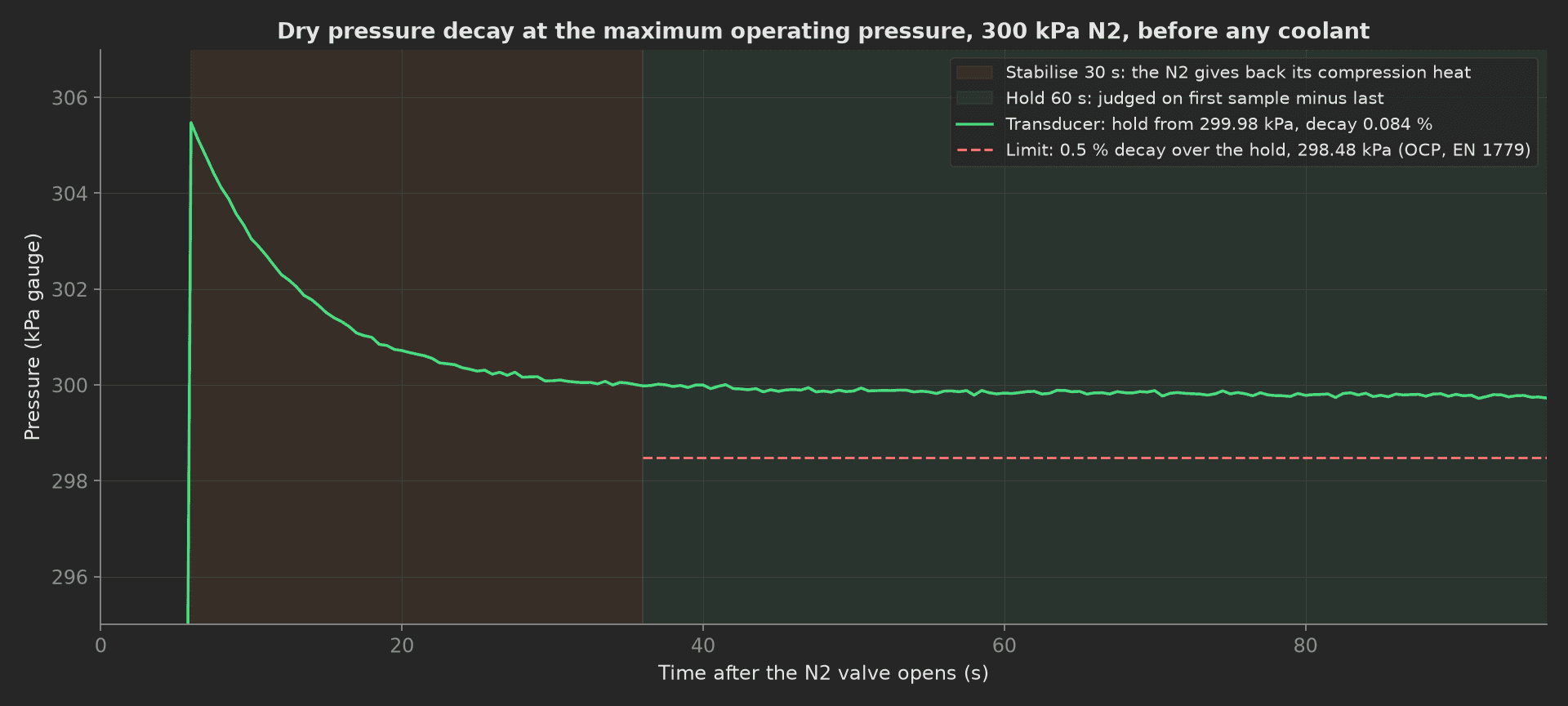
The mock plate's decay: 5.5 kPa of compression heat relaxing with a 7 s time constant through the stabilise window, then 0.25 kPa lost over the hold, 0.084 % against 0.5 %. The mock returns the 96 s trace in one call; a real bench records it. A stub seated on its first detent but not its second shows a decay ten times steeper, and the YAML's then: {fail: retry} gives the operator one re-seat before the run stops.
Hydrostatic
Filled with PG25 from the bench pump, ramped to 1x the maximum operating pressure and held for 5 min with the pump isolated, then to 3x for 2 min, then vented. The phase finds each dwell in the trace and reports its minimum; a leak, a weeping braze or a lid lifting off its seal shows as a falling trace during the dwell, not as a pump working harder. The operator's inspection after the 3x dwell lands as no_deformation through the switch bound to it.
phases/hydrostatic.py34 lines
import numpy as npfrom utils.recipe import HYDRO_1X_DWELL_S, HYDRO_3X_DWELL_S, MOP_KPAdef dwell_min(t, p, target_kpa, dwell_s): """Lowest pressure inside the dwell at the stated target: the samples within 2 % of the target, the last dwell_s worth of them.""" at_target = np.where(np.abs(p - target_kpa) < 0.02 * target_kpa)[0] end = t[at_target[-1]] window = (t > end - dwell_s) & (t <= end) return float(p[window].min())def hydrostatic(measurements, bench, log): """Filled with PG25, 1x the maximum operating pressure for 5 min then 3x for 2 min (IEC 62368-1 as OCP quotes it), pump isolated during each dwell so a leak shows as a falling trace. The operator's inspection of the plate after the 3x dwell lands as the no_deformation measurement through the switch bound to it; the phase waits for that answer once the trace is recorded.""" bench.fill() t_s, p_kpa = bench.hydrostatic(MOP_KPA, HYDRO_1X_DWELL_S, HYDRO_3X_DWELL_S) t = np.asarray(t_s) p = np.asarray(p_kpa) min_1x = dwell_min(t, p, MOP_KPA, HYDRO_1X_DWELL_S) min_3x = dwell_min(t, p, 3.0 * MOP_KPA, HYDRO_3X_DWELL_S) m = measurements.hydrostatic m.x_axis = t_s m.y_axis.pressure = p_kpa m.y_axis.pressure.aggregations.min_1x_dwell_kpa = round(min_1x, 1) m.y_axis.pressure.aggregations.min_3x_dwell_kpa = round(min_3x, 1) log.info(f"1x MOP dwell held {min_1x:.1f} kPa of {MOP_KPA:.0f}, 3x dwell {min_3x:.1f} kPa of {3 * MOP_KPA:.0f} (mock: the {t[-1]:.0f} s trace is returned at once)")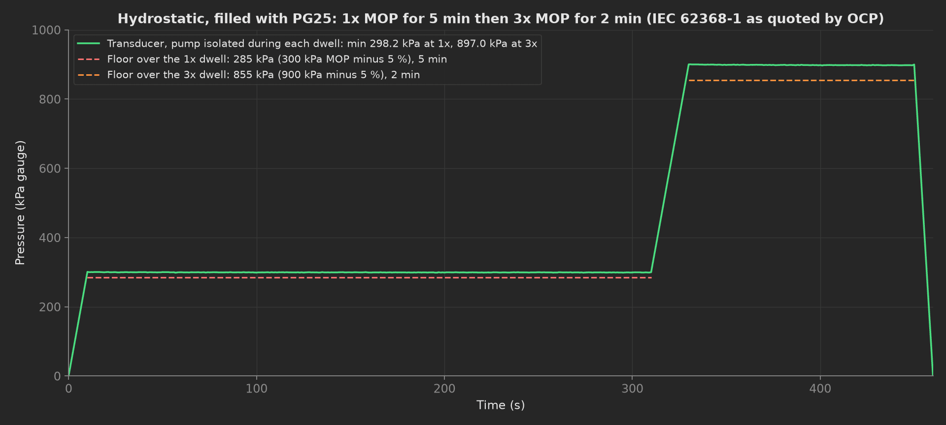
The mock plate holds 298.2 kPa of 300 and 897.0 of 900, the small settle coming from the hoses' compliance. The 5 and 2 min dwells are the spec's; the mock returns the 460 s trace in one call, so the run does not wait the seven minutes a real bench does.
Flow and Pressure Drop
Six flows from half to a third above the design flow. At each point the loop dP is read with the plate in, then again through the bypass with the plate isolated, and the plate's own dP is the difference: the hoses, the quick-disconnects and the fixture are the same in both readings and cancel. The velocity in the stubs comes from the measured flow and the bore, and is the OCP erosion limit for copper.
phases/flow_pressure_drop.py38 lines
import mathimport numpy as npfrom utils.recipe import DESIGN_FLOW_LPM, FLOW_SWEEP_LPM, PORT_ID_MMdef flow_pressure_drop(measurements, bench, log): """Flow sweep at six points around the design flow. At each point the loop dP is read with the plate in and again through the bypass, and the plate's own dP is the difference (OCP), so the hoses, the QDs and the fixture do not end up in the plate's number. The velocity in the QD stubs comes from the measured flow and the bore.""" area_m2 = math.pi * (PORT_ID_MM / 2000.0) ** 2 flows, net, loop, bypass, velocity = [], [], [], [], [] for q in FLOW_SWEEP_LPM: bench.set_flow_lpm(q) measured = bench.flow_lpm() with_plate = bench.dp_kpa("plate") through_bypass = bench.dp_kpa("bypass") flows.append(measured) loop.append(with_plate) bypass.append(through_bypass) net.append(with_plate - through_bypass) velocity.append(measured / 60000.0 / area_m2) log.info(f"{measured:.3f} LPM: loop {with_plate:.2f} kPa, bypass {through_bypass:.2f} kPa, plate {net[-1]:.2f} kPa, {velocity[-1]:.2f} m/s in the stubs") bench.set_flow_lpm(DESIGN_FLOW_LPM) at_design = int(np.argmin(np.abs(np.asarray(flows) - DESIGN_FLOW_LPM))) m = measurements.flow_curve m.x_axis = [round(q, 3) for q in flows] m.y_axis.plate_dp = [round(v, 3) for v in net] m.y_axis.plate_dp.aggregations.at_design_flow_kpa = round(net[at_design], 2) m.y_axis.loop_dp = loop m.y_axis.bypass_dp = bypass m.y_axis.stub_velocity = [round(v, 3) for v in velocity] m.y_axis.stub_velocity.aggregations.at_design_flow_m_s = round(velocity[at_design], 3) log.info(f"Plate dP {net[at_design]:.2f} kPa at {flows[at_design]:.2f} LPM, {velocity[at_design]:.2f} m/s in a {PORT_ID_MM:.0f} mm bore")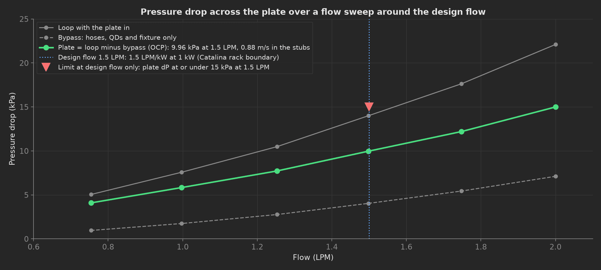
The mock plate: 9.96 kPa at 1.5 LPM and 0.88 m/s in a 6 mm bore, with the bypass taking 4 kPa of the 14 the loop shows. The curve is a laminar term in the fins plus a square term in the manifolds, so it bends upward; the limit applies at the design flow only and is drawn there only, because the same plate at 2 LPM reads 15 kPa and is not failing anything.
Thermal Resistance
Four power steps to 1 kW at the design flow, the supply held at 40 C, 180 s of settling at each on a real bench. R = (Tcase - Tinlet) / P at every step; the mean and the full-power value each carry the limit. The outlet RTD closes the energy balance at 1 kW: the coolant must carry away what the heater put in, within 10 %, or a channel is blocked and the case RTD is reading a hot spot the plate is not cooling. The inlet mean is judged too, since an R measured against a drifting supply is not an R.
phases/thermal_resistance.py36 lines
import numpy as npfrom utils.recipe import DESIGN_FLOW_LPM, PG25_CP_J_PER_KG_K, PG25_DENSITY_KG_L, POWER_STEPS_W, STEADY_STATE_Sdef thermal_resistance(measurements, bench, log): """Heater block at four power steps up to 1 kW at the design flow, the supply held at 40 C. R = (Tcase - Tinlet) / P at each step (OCP). The outlet RTD closes the energy balance at full power: the coolant must carry away what the heater put in, or a channel is blocked and the case RTD is reading a hot spot the plate is not cooling.""" bench.set_flow_lpm(DESIGN_FLOW_LPM) m_cp = DESIGN_FLOW_LPM / 60.0 * PG25_DENSITY_KG_L * PG25_CP_J_PER_KG_K tin_c, tcase_c, r = [], [], [] balance = None for p in POWER_STEPS_W: bench.set_heater_w(p) log.info(f"{p:.0f} W: settle {STEADY_STATE_S:.0f} s (mock: instant)") tin, tout, tcase = bench.rtds_c() tin_c.append(tin) tcase_c.append(tcase) r.append((tcase - tin) / p) balance = 100.0 * m_cp * (tout - tin) / p log.info(f"{p:.0f} W: inlet {tin:.2f} C, outlet {tout:.2f} C, case {tcase:.2f} C, R {r[-1]:.4f} K/W, coolant carries {balance:.1f} %") bench.set_heater_w(0.0) m = measurements.thermal_curve m.x_axis = POWER_STEPS_W m.y_axis.tcase_c = tcase_c m.y_axis.tcase_c.aggregations.max_c = round(max(tcase_c), 2) m.y_axis.tin_c = tin_c m.y_axis.tin_c.aggregations.mean_c = round(float(np.mean(tin_c)), 2) m.y_axis.r_k_per_w = [round(v, 5) for v in r] m.y_axis.r_k_per_w.aggregations.mean_k_per_w = round(float(np.mean(r)), 4) m.y_axis.r_k_per_w.aggregations.at_full_power_k_per_w = round(r[-1], 4) measurements.coolant_heat_balance_pct = round(balance, 1)The 0.020 K/W limit is not in the OCP paper; it is what a 60 C case ceiling leaves on a 40 C supply for a 1 kW device, and a plate that passes it at this interface has the headroom the product's own TIM tolerance will consume.
Particulate Flush
Ten minutes at twice the design flow through the inline 50 um filter, the effluent through the particle counter. The counts per 100 mL in each size bin are recorded as one curve, and the bin above 50 um is the one judged, at zero. The filter's own dP is read at the start and at the end of the flush: a filter still loading when the flush ends is a plate still shedding, whatever the counter said in the last sample.
from utils.recipe import FILTER_DP_RISE_MAX_KPA, FLUSH_FLOW_LPM, FLUSH_MIN, PARTICLE_BINS_UMdef particulate_flush(measurements, bench, log): """Flush at twice the design flow through the inline 50 um filter with the effluent through the particle counter. OCP's rule is nothing above 50 um; the counts per 100 mL in every size bin are recorded, and the filter's own dP must have stopped rising, or the flush ended while the plate was still shedding.""" counts, dp_start, dp_end = bench.flush(FLUSH_FLOW_LPM, FLUSH_MIN) rise = dp_end - dp_start m = measurements.particle_counts m.x_axis = PARTICLE_BINS_UM m.y_axis.count = counts m.y_axis.count.aggregations.over_50um = counts[-1] measurements.filter_dp_stable = rise < FILTER_DP_RISE_MAX_KPA log.info(f"{FLUSH_MIN:.0f} min at {FLUSH_FLOW_LPM:.1f} LPM (mock: instant): counts {counts} per 100 mL from {[int(b) for b in PARTICLE_BINS_UM]} um, filter dP {dp_start:.2f} to {dp_end:.2f} kPa")Drain and Cap
The teardown drains the plate, blows it down with N2 for 60 s, fits the shipping caps and puts the plate back on the scale. The residual is the wet mass minus the dry tare that the identify phase recorded, read through the injected result of that phase. The raw pressure traces of the decay and the hydrostatic go with the run as one JSON attachment.
import jsonfrom utils.recipe import BLOW_DOWN_Sdef drain_and_cap(measurements, bench, attach, identify, log): """Teardown: drain, N2 blow-down, caps on both quick-disconnects, the plate back on the scale. The residual is the wet mass minus the dry tare the identify phase recorded, read through the injected result of that phase. The raw pressure traces of the decay and the hydrostatic go with the run as one JSON attachment.""" bench.drain_and_blow_down(BLOW_DOWN_S) capped = bench.cap_qds() residual = bench.wet_mass_g() - identify.dry_mass_g measurements.residual_coolant_g = round(residual, 2) measurements.qds_capped = capped attach.data(json.dumps(bench.pressure_log()).encode(), "pressure-log.json") log.info(f"Blow-down {BLOW_DOWN_S:.0f} s (mock: instant), {residual:.2f} g of coolant left, caps {'fitted' if capped else 'missing'}, pressure log attached")Mock Plug
ColdPlateBench stands in for the whole bench and the plate because every reading depends on what the pump and the heater are doing at that instant, and plugs run in separate processes. Its decay is 5.5 kPa of compression heat with a 7 s time constant over a leak of 0.0027 kPa/s, its hydrostatic dwells settle 0.9 and 2.5 kPa on the hose compliance, its pressure drop is 4.2 kPa/LPM in the fins plus 1.6 kPa/LPM squared in the manifolds with a bypass of 1.78 kPa/LPM squared, its thermal resistance 0.0157 K/W rising 0.0003 per kW, its coolant carrying 97 % of the heater power, its effluent 286, 71, 6 and 0 counts per 100 mL from 5, 10, 25 and 50 um, and its residual 1.8 g. Time is scaled: the 96 s decay, the 460 s hydrostatic, the 180 s settles and the 10 min flush are returned as traces or values in one call, and each phase logs that it did so. Every method returns plain Python types because plug calls cross a JSON boundary; a measurement read back from measurements.<key> returns a proxy, so the phases keep locals for their log lines.
On a real bench, split the class into the N2 side, the pump and its isolation valve, the flow loop with its meter and dP cells, the chiller, the heater controller and the RTD reader, the particle counter, the conductivity probe and the scale, over Modbus, SCPI or their vendor drivers. Record the pressure traces at the transducer's rate and let the phases compute the decay and the dwell minima; wait the real 180 s per power step and the real 10 min flush, the timeout values are sized for them; and keep the same heater pedestal and thermal interface for every plate. The phases, measurements and limits stay the same.