
Get the complete source, dependencies and setup instructions from the template repository.
Open the source on GitHubIntroduction
LiPo Battery Overview
The lithium-polymer (LiPo) battery is one of the most expensive components in a drone bill of materials, and mishandled packs are the main fire hazard on a production floor. A 6S 22,000 mAh cargo-drone pack costs more than the autopilot, the camera, and the gimbal combined, and one defective cell can take down a $50,000 airframe mid-flight. Cell voltage swings from 4.20 V/cell fully charged to 3.30 V/cell under-load cutoff, with deep discharge below 3.0 V/cell causing irreversible damage. The pack is a series-parallel string, and a single weak cell drags the entire pack: capacity is gated by the worst cell, not the average.
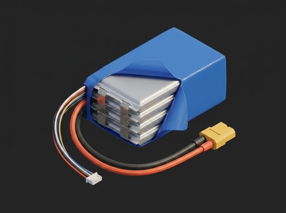
A 4S pack under the shrink wrap: four pouch cells in series, the balance lead tapping every cell junction, the XT60 main leads carrying the load current.
The cell vendor's COA covers cells before assembly; everything that happens after (tab welding, balance lead wiring, BMS configuration, storage at the wrong SOC) is on the pack assembler. End-of-line discharge profiling catches these defects per-pack before the customer's first crash.
Test Purpose
The procedure produces a per-pack health fingerprint:
- Capacity delivered in mAh from full charge to cutoff at controlled C-rate
- DC internal resistance per cell, measured via short high-current pulse
- Cell imbalance maximum across the discharge envelope
- Burst voltage sag under a simulated motor demand transient
- Temperature rise during full discharge
- OCV-SOC curve for state-of-charge estimation calibration
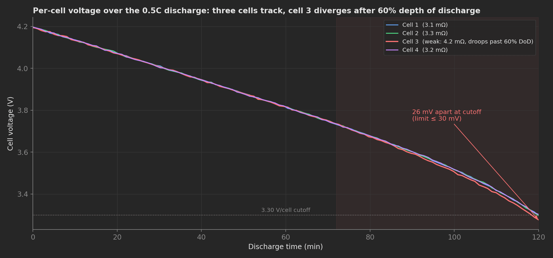
The mock pack's discharge: three cells track to within a few millivolts, the weak cell 3 droops after 60% depth of discharge and finishes 26 mV below the others, just inside the 30 mV imbalance limit.
Per-pack profiling catches weak cells, internal micro-shorts (very low IR), tab cold-solder joints, miswired balance leads, and BMS misconfig. End-of-discharge state is set to 3.85 V/cell storage SOC (commonly treated as ~50%) or 3.70-3.75 V/cell for air-shipped packs: the IATA Lithium Battery Guidance Document (DGR 67th edition, 2026) requires batteries shipped alone under PI 965 at a state of charge not exceeding 30% of rated capacity, and since 2026 the same limit applies to packs shipped with equipment under PI 966. The rule is written in percent SOC, not volts, so verify the voltage targets against your cell's OCV-SOC table.
Equipment & Setup
To implement LiPo discharge profiling on a production line, the following are required:
- A programmable DC electronic load with CC and pulse modes, sized for pack voltage and peak C-rate
- A balance-lead breakout for per-cell voltage sensing
- Thermocouples on cell surfaces (or pack thermistor)
- The Device Under Test (DUT): a fully charged LiPo pack
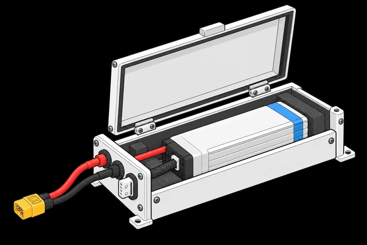
- A safety enclosure (LiPo bunker) with thermal monitoring and emergency cutoff
- A TofuPilot Framework procedure to script the cycle, log measurements, and validate metrics
- The TofuPilot Dashboard to store per-pack health data for traceability and supplier-quality trending
Hardware Components
Electronic Load
For production lines, the Chroma 63200A series is the reference: CC / CR / CV / CP modes, voltage and time stops, 2-24 kW per unit parallelable to 240 kW, up to 2,000 A per unit, and 300% peak overpower for burst pulses, with master/slave control for batch parallel discharge. For tight transient capture (burst sag), the Kikusui PLZ-4W series offers 10 µs rise/fall, which catches the full transient response of a 10C burst (the PLZ164WA and PLZ664WA are the series' 0 V-input models).
For lab and small-volume production, the iCharger 4010 Duo (2 × 40 A, up to 10S) is the affordable workhorse, with one important caveat for this procedure: its internal discharge capability is 130 W per channel; the headline 1400 W figure applies to regenerative discharge into a supply battery. For incoming inspection of bare cells or 1S validation, the ZKETech EBC-A40L covers 40 A charge/discharge at ≤5 V.
The pack is supported in a cradle with separate main power and balance harnesses. The electronic load and measurement instruments are not shown.
Per-Cell Sensing
A balance-lead breakout (XH for ≤6S, PH for larger) routes each cell tap to a multiplexed ADC. Per-cell voltages are read at 1 Hz throughout discharge. Pack-only voltage is insufficient: a 4S pack reading 14.8 V can hide one cell at 3.0 V and three cells at 3.93 V.
Thermal Monitoring
Type-K thermocouples bonded to two cells (center and edge of the pack), or a pack-integrated thermistor pre-wired by the pack assembler. For visual QA, a FLIR E8-XT thermal camera (320×240, -20 to 550 °C, MSX overlay, IP54) captures post-discharge thermal images, flagging asymmetric heating from a weak cell or a bad tab weld.
Safety Bunker
LiPo discharge must run inside a steel-walled bunker lined with vermiculite or CellBlockEX thermal-runaway suppressant. Adjacent fire-suppression: a sand bucket (CO₂ and dry chem don't stop lithium reignition). Hardware interlocks for OVP, UVP, and OTP wired to the load contactor, never software-only. The production line alarms and disconnects the load at dT/dt > 5 °C/min or T > 60 °C. These are deliberately conservative early-warning limits: formal thermal-runaway detection criteria in standards work trigger much later, around dT/dt ≥ 1 °C/second (see the JRC evaluation of detection criteria), at which point suppression, not prevention, is what remains.
Cycle Parameters
Discharge at 0.5C constant current (1C for high-C packs) from full charge to 3.30 V/cell cutoff, logging per-cell voltage, current, and temperature at 1 Hz. The IR pulse applies 5C for 2 s at 50% SOC after a 30 min rest; the burst applies 10C for 200 ms at 30% SOC, captured at ≥1 kHz. The pack ends at the storage SOC target above. A 0.5C discharge takes ~2 hours regardless of capacity (rate-limited, not capacity-limited); batch-parallel discharge across 8-16 bunker cells per master/slave rack amortizes cycle time.
Test Procedure
Overview
The procedure maps the cycle onto the framework's three stages. Safety lives in setup:, so no current flows before the operator arms the interlock. The recharge lives in teardown:, so the framework runs it even when a main phase fails and no pack is ever left at full charge in the bunker.
- Setup: interlock confirmation plus electrical sanity checks.
- Main: CC capacity discharge with per-cell logging, bounded by a phase timeout.
- Main: IR pulse and per-cell DC resistance computation.
- Main: burst sag transient, split into ESR and polarization.
- Main (disabled by default): optional FLIR thermal capture.
- Teardown: recharge to storage SOC, always executed.
Every metric validates against limits declared in procedure.yaml, and results stream to TofuPilot for traceability and analytics.
Why TofuPilot Framework?
TofuPilot Framework is a YAML + Python test framework built for hardware manufacturing. Instead of writing all your test logic, measurements, and limits inside Python code, you describe what the test does in a procedure.yaml file, and how in small Python phase files. The framework handles:
- Automatic Python environment management (via
uv) - Operator UI (no frontend code needed)
- Measurement validation and live charts
- Process isolation between phases and equipment plugs
This template additionally demonstrates setup and teardown stages, a phase timeout, a disabled phase, unit metadata, and an operator interlock switch bound to a validated measurement.
Project Structure
You can find the full source on GitHub. The BatteryBench plug is a mock that synthesizes a 4S pack with one slightly weak cell, so the procedure runs end-to-end without a pack or an electronic load connected. The mock is time-scaled: it returns the whole 2-hour discharge in one call so a run finishes in seconds. This is also why the discharge phase carries timeout: 120s; a production procedure driving a real load would set e.g. timeout: 3h to bound the actual discharge duration.
tofupilot run .For CI or bench automation, ui.json pre-bakes the operator inputs and the run executes headless:
tofupilot run . --no-tui --json --ui-values ui.json --ui-timeout 60The Procedure File
procedure.yaml declares the unit (auto-identified, with a cell lot metadata field), the bench plug with its config passed as constructor arguments, and the three stages. The main-phase measurement declarations are abridged here and shown in their sections below:
procedure.yaml86 lines
name: LiPo Discharge and IR Profilingversion: 0.1.0description: Controlled discharge cycle on a drone LiPo pack with per-cell logging, DC internal resistance pulse, burst sag capture, and recharge to storage SOC.plugs: - name: Battery Bench description: Electronic load and balance-lead ADC. Mock replays a synthetic 4S pack with one weak cell. python: plugs.battery_bench:BatteryBench key: bench config: cell_count: 4 capacity_mah: 3000unit: auto_identify: true serial_number: default_value: "PACK-000123" part_number: default_value: "LIPO-4S-3000" batch_number: default_value: "BATCH-2026-031" metadata: cell_lot: description: "Cell vendor lot code printed on the pouch edge" placeholder: "LOT-XXXX" default_value: "LOT-8842"setup: - name: Safety Check key: safety_check python: phases.safety_check measurements: - name: Interlock Armed key: interlock_armed validators: - operator: "==" expected_value: true - name: Cells At Full Charge key: cells_full validators: - operator: "==" expected_value: true ui: components: - key: interlock type: switch label: "Bunker interlock armed" description: "Confirm the pack is inside the bunker and the hardware interlock is armed" required: true bind: measurements.interlock_armedmain: - name: CC Discharge key: cc_discharge python: phases.cc_discharge timeout: 120s # mock is time-scaled; a real 0.5C discharge needs e.g. 3h - name: IR Pulse key: ir_pulse python: phases.ir_pulse depends_on: [cc_discharge] - name: Burst Sag key: burst_sag python: phases.burst_sag depends_on: [ir_pulse] - name: Thermal Capture key: thermal_capture python: phases.thermal_capture enabled: false depends_on: [burst_sag]teardown: - name: Recharge To Storage key: recharge_storage python: phases.recharge_storage measurements: - name: Storage Voltage key: storage_voltage_v unit: V/cell validators: - operator: ">=" expected_value: 3.80 - operator: "<=" expected_value: 3.90Three framework behaviors carry the safety story:
- The
setup:stage must pass before any main phase runs, so the interlock switch gates the discharge. - The
teardown:stage always runs, even after a failed or errored main phase, so the pack always ends at storage SOC. - The
timeout:on the discharge bounds the phase; a load stuck in CC mode ends the phase with a timeout outcome instead of running forever.
The Thermal Capture phase ships with enabled: false: it is skipped silently without recording results. Lines equipped with a FLIR camera flip it on without touching code.
Safety Check Phase
The operator switch is bound to the interlock_armed measurement with bind: measurements.interlock_armed, and the measurement validates == true. The run report records what the operator actually confirmed, not just that a button was pressed. The phase verifies every cell sits at full charge (4.20 V ±0.02) before allowing the discharge, warns on pack temperature outside the 20-25 °C window, and stamps the BMS firmware onto the unit metadata, next to the cell lot collected from YAML:
def safety_check(measurements, bench, unit, log): """Pre-discharge check: interlock (operator switch, bound to a measurement) plus electrical sanity read from the bench.""" log.info(f"Pack {unit.serial_number}, cell lot {unit.metadata.get('cell_lot')}") unit.metadata["bms_fw"] = "1.7.2" cells = bench.cell_voltages() measurements.cells_full = all(4.18 <= v <= 4.22 for v in cells) log.info(f"Cell voltages {[f'{v:.3f}' for v in cells]} V") temp = bench.pack_temperature() if not 20.0 <= temp <= 25.0: log.warning(f"Pack temperature {temp:.1f} C outside 20-25 C window") log.info(f"Pack temperature {temp:.1f} C")Hardware interlocks for OVP, UVP, and OTP stay wired to the load contactor. The software check is the operator-facing layer, not the protection.
CC Capacity Discharge
The load runs 0.5C constant current to 3.30 V/cell, logging per-cell voltages. The four cell curves land in a single multi-dimensional measurement with four Y axes, which the dashboard renders as one interactive chart. A weak cell diverging past 60% depth of discharge is visible at a glance, and the imbalance limit catches it numerically:
phases/cc_discharge.py28 lines
import numpy as npdef cc_discharge(measurements, bench, phase, log): """0.5C constant-current discharge to 3.30 V/cell with per-cell logging.""" data = bench.discharge_capture(0.5, 3.30) # Hardware interlocks are the real protection; this software guard # alerts the operator before the bunker suppression has to act. It # sits after the capture only because the mock returns a completed # capture in one call; a real bench polls temperature_rate() inside # the acquisition loop and stops mid-discharge. if bench.temperature_rate() > 5.0: log.error("Thermal runaway onset detected, stopping run") phase.stop() cells = np.array(data["cells_v"]) measurements.discharge_curves.x_axis = data["time_s"] measurements.discharge_curves.y_axis.cell_1 = data["cells_v"][0] measurements.discharge_curves.y_axis.cell_2 = data["cells_v"][1] measurements.discharge_curves.y_axis.cell_3 = data["cells_v"][2] measurements.discharge_curves.y_axis.cell_4 = data["cells_v"][3] measurements.capacity_delivered_pct = 100.0 * data["delivered_mah"] / data["capacity_mah"] measurements.imbalance_max_mv = float((cells.max(axis=0) - cells.min(axis=0)).max() * 1000.0) temps = np.array(data["pack_temp_c"]) measurements.temp_rise_k = float(temps.max() - temps[0]) log.info(f"Delivered {data['delivered_mah']:.0f} mAh")phase.stop() aborts the entire run on early runaway warning (dT/dt above 5 K/min, well below the ~1 °C/s onset criteria used in standards work), and the teardown recharge still executes afterwards. In this mock the guard runs after the capture because the mock returns a completed capture in one call; a real bench polls the rate inside its acquisition loop. The corresponding measurement declarations:
procedure.yaml27 lines
measurements: - name: Discharge Curves key: discharge_curves title: Per-Cell Discharge Curves x_axis: legend: Time unit: s y_axis: - {legend: Cell 1, key: cell_1, unit: V} - {legend: Cell 2, key: cell_2, unit: V} - {legend: Cell 3, key: cell_3, unit: V} - {legend: Cell 4, key: cell_4, unit: V} - name: Capacity Delivered key: capacity_delivered_pct unit: "%" validators: - {operator: ">=", expected_value: 95.0} - name: Max Cell Imbalance key: imbalance_max_mv unit: mV validators: - {operator: "<=", expected_value: 30.0} - name: Temperature Rise key: temp_rise_k unit: K validators: - {operator: "<=", expected_value: 25.0}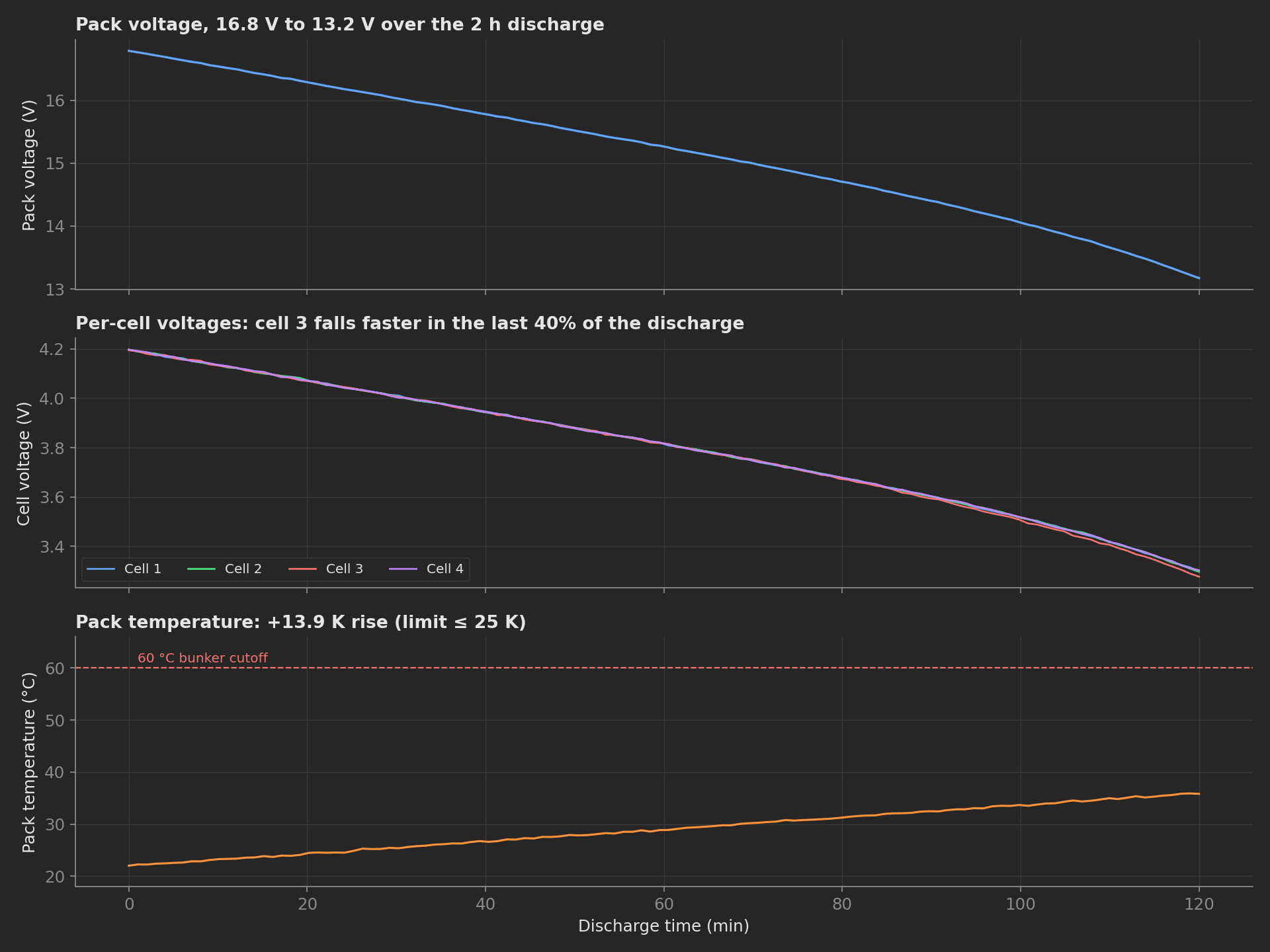
What the station logs at 1 Hz over the two hours: pack voltage, the four cell voltages, and pack temperature, which rises 14 K against the 25 K limit and stays far from the 60 °C bunker cutoff.
Internal Resistance Pulse
At 50% SOC, after a rest to settle polarization, the load applies a 5C pulse for 2 s. The phase samples per-cell voltage just before the pulse (V_open) and 100-200 ms into the pulse (V_load). R_DC per cell = (V_open - V_load) / I_pulse. DC IR runs higher than 1 kHz AC IR because it includes charge-transfer resistance on top of the ohmic part, which is exactly why it predicts real-world voltage sag better (see Hioki's white paper on Li-ion internal resistance testing):
import numpy as npdef ir_pulse(measurements, bench, log): """DC IR per cell from a 2 s 5C pulse at 50% SOC: R = dV / dI.""" pulse = bench.ir_pulse(5.0, 2.0) dv = np.array(pulse["v_open"]) - np.array(pulse["v_load"]) ir_mohm = dv / pulse["current_a"] * 1000.0 for i, r in enumerate(ir_mohm): log.info(f"Cell {i + 1}: {r:.2f} mOhm") measurements.ir_max_mohm = float(ir_mohm.max()) measurements.ir_spread_mohm = float(ir_mohm.max() - ir_mohm.min())The declared limits: max cell IR 2-8 mΩ (a value below 2 suggests an internal micro-short, above 8 a bad tab weld) and IR spread below 1.5 mΩ across the pack:
measurements: - name: Max Cell IR key: ir_max_mohm unit: mΩ validators: - {operator: ">=", expected_value: 2.0} - {operator: "<=", expected_value: 8.0} - name: IR Spread key: ir_spread_mohm unit: mΩ validators: - {operator: "<=", expected_value: 1.5}Burst Sag Transient
At 30% SOC, a 10C burst for 200 ms simulates a motor demand transient, captured at 1 kHz. The instantaneous step at burst onset is ESR (ohmic); the slower exponential droop is polarization. The phase reports the worst-cell total sag and the ESR share:
import numpy as npdef burst_sag(measurements, bench, log): """10C 200 ms burst at 30% SOC. The instantaneous step at burst onset is ohmic (ESR); the exponential droop that follows is polarization.""" burst = bench.burst_capture(10.0, 200) v = np.array(burst["worst_cell_v"]) sag_total = float(v[0] - v.min()) esr_share = 100.0 * burst["esr_drop_v"] / sag_total measurements.sag_max_v = sag_total measurements.esr_share_pct = esr_share log.info(f"Sag {sag_total:.3f} V, ESR share {esr_share:.0f}%")The worst-cell sag validates <= 0.4 V; the ESR share is recorded without validators, so it lands in the report with an UNSET outcome that does not affect pass/fail but stays trendable:
measurements: - name: Worst Cell Sag key: sag_max_v unit: V validators: - {operator: "<=", expected_value: 0.4} - name: ESR Share key: esr_share_pct unit: "%"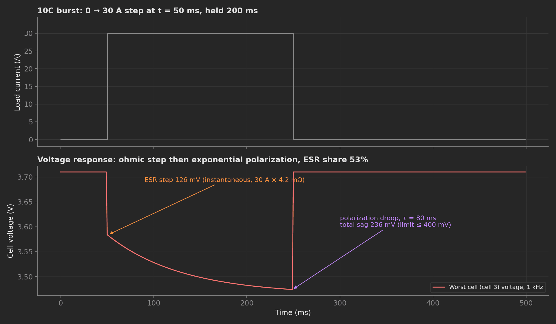
The burst on the mock's weak cell: 30 A into 4.2 mΩ gives the 126 mV ohmic step, the 80 ms polarization droop adds another 110 mV, and the 236 mV total stays under the 400 mV limit with the ESR share at 53%.
Recharge to Storage SOC
The teardown phase recharges CC/CV to 3.85 V/cell with active balancing (3.70-3.75 V/cell for air-shipped packs, per the IATA 30% SOC rule above), and validates the final per-cell voltage as the last QA check:
import numpy as npdef recharge_storage(measurements, bench, log): """Teardown: always runs, even when a main phase failed, so no pack is ever left at full charge in the bunker.""" cells = bench.recharge_to_storage(3.85) storage_v = float(np.mean(cells)) measurements.storage_voltage_v = storage_v log.info(f"Pack stored at {storage_v:.3f} V/cell")Mock Bench Plug
The BatteryBench plug simulates the load and balance ADC, generating a synthetic 4S pack whose cell 3 has elevated IR and droops past 60% depth of discharge. Its config block in YAML becomes constructor arguments, so pack chemistry lives in the procedure file, not the code. Swap the class for one speaking SCPI to a Chroma or Kikusui load; the phases stay unchanged.
Note two framework behaviors visible in the phase code: plug attributes are not readable across the process boundary (only method calls are proxied, which is why the mock returns capacity_mah inside the data dict), and a measurement read back from measurements.<key> returns a proxy, so keep a local variable when you need to format the value for a log line.