
Get the complete source, dependencies and setup instructions from the template repository.
Open the source on GitHubIntroduction
Functional Test Overview
Functional Test (FCT) exercises a PCBA as a complete working system under simulated end-use conditions: powers the board, boots firmware, drives every interface, and verifies outputs against spec. It answers "does it work as intended" rather than ICT's "was it built correctly." FCT catches what ICT and boundary scan miss because both are static or component-level: firmware bugs, marginal regulator dropout, hardware-software interaction faults, brownout-induced corruption, and timing margins only show up when the board runs at speed.
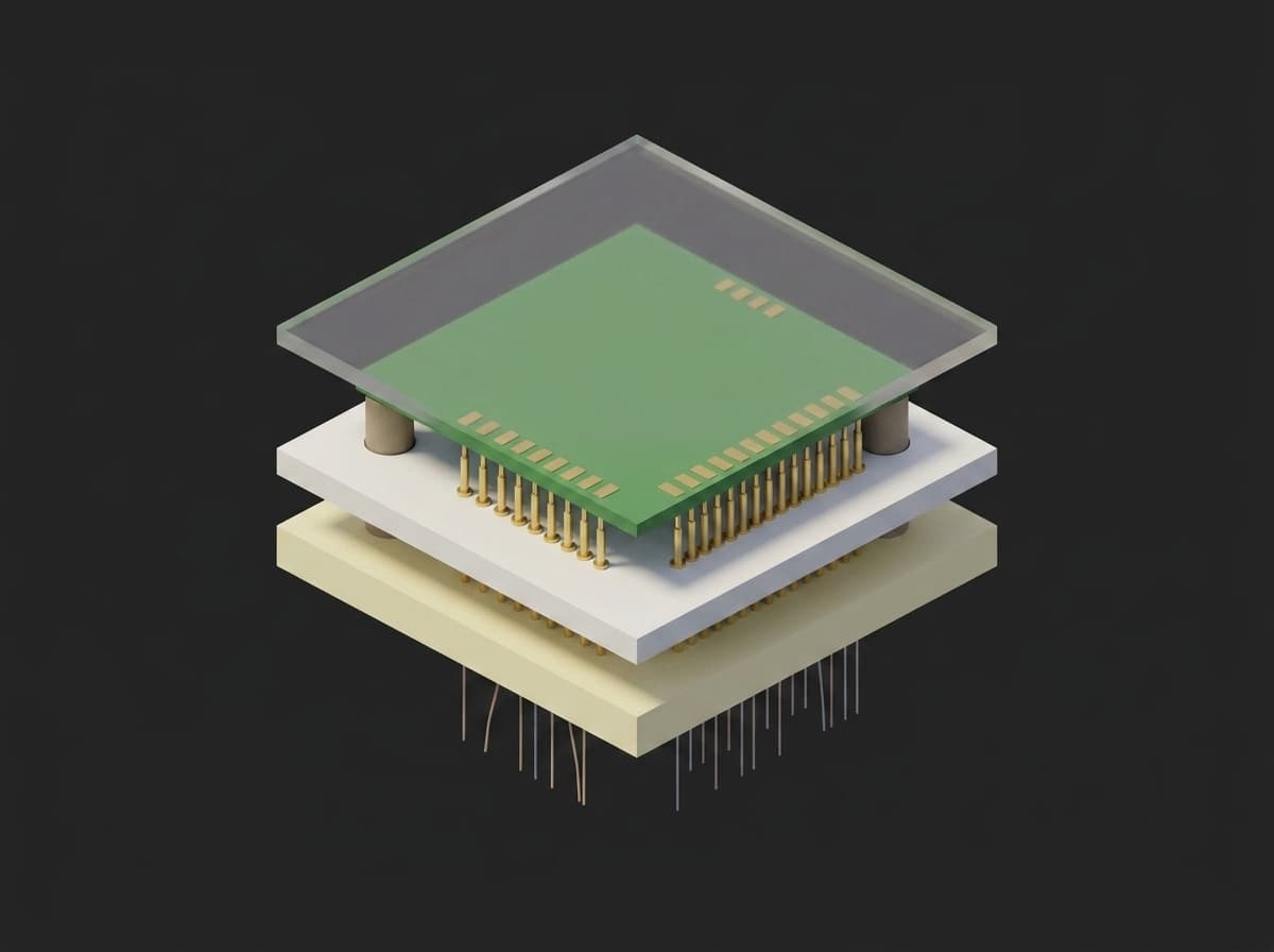
Inside the fixture: tooling pins locate the board, spring probes in the probe plate reach the test pads from below, the backer plate carries the wiring to the instruments, the top plate holds the board down at a controlled stroke.
The typical production flow is ICT first (structural) then FCT (system behavior). Defects that escape ICT, a wrong firmware revision, a peripheral solder defect that does not fail continuity, a regulator marginal under load, get caught at FCT before the unit ships.
Test Purpose
The FCT procedure produces a per-board functional fingerprint:
- Power-up behavior: inrush peak and steady-state current on a soft-start ramp
- Rail voltages and ripple at every regulator output
- Firmware handshake: test mode entered, firmware version, hardware revision
- GPIO loopback on every channel, high and low
- ADC linearity: gain error, offset and R² over a stimulus sweep
- Operator checks for what the fixture cannot measure cheaply, backed by photodiodes
- Stop-mode current for battery-powered designs
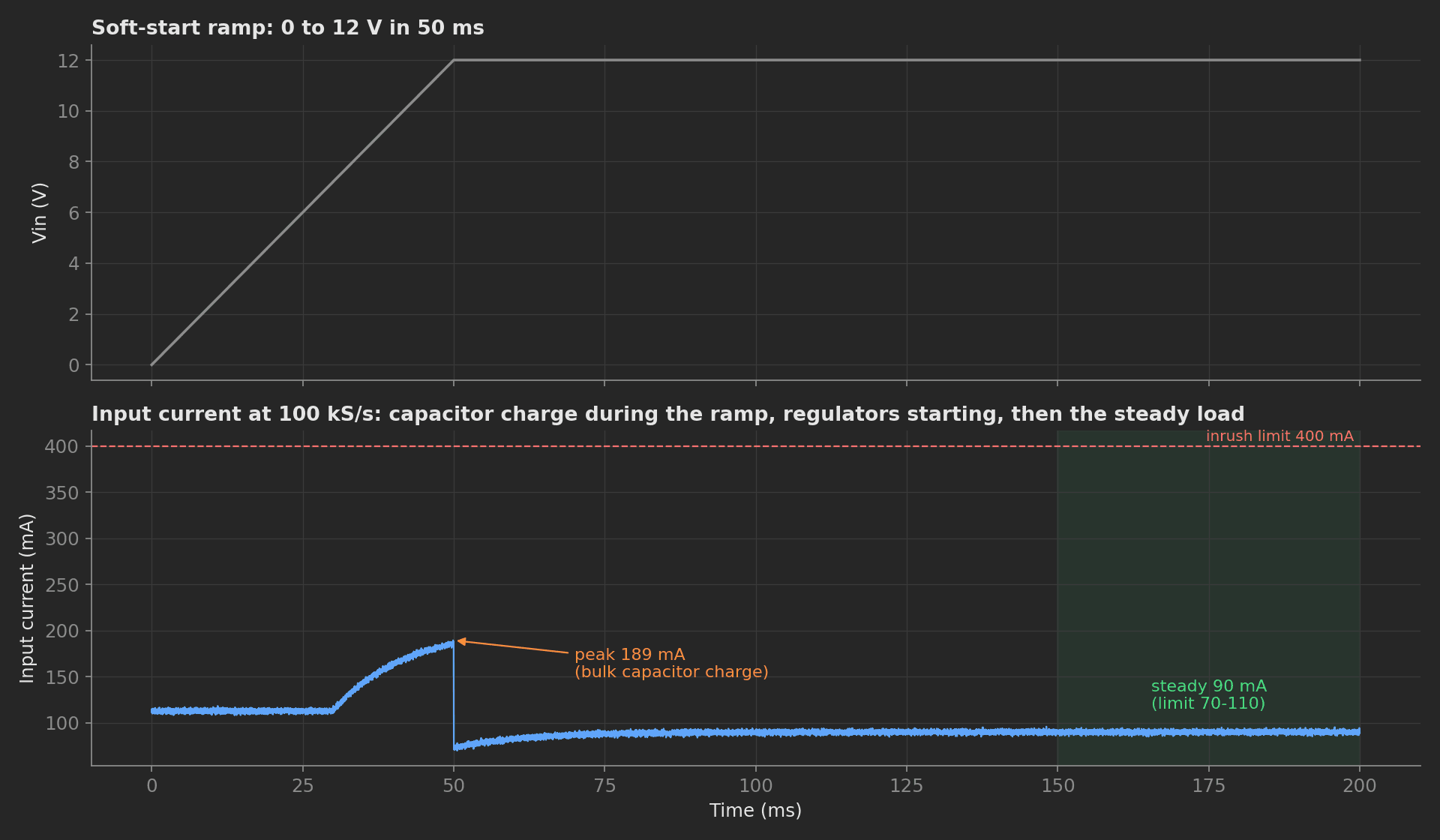
The power-on capture from the mock supply: constant capacitor current while Vin ramps, the regulators loading as they start, then the steady draw. A shorted output capacitor or a dead regulator changes this trace before any rail reads wrong.
Per-board FCT is the last line of defense before shipment. It eliminates the leading category of returns: "doesn't boot", "GPIO output stuck", "battery dies in three days", all invisible to ICT and AOI.
Beyond the test content, this template demonstrates five framework mechanics: a setup stage that gates power on the fixture interlock, a phase DAG where three phases fan out from the handshake and the sleep measurement fans them back in, progress components driven from Python during the sweeps, operator switches bound to boolean measurements with pre-baked answers for unattended runs, and run metadata carrying the fixture identity and cycle count.
Equipment & Setup
To implement FCT on a production line, the following are required:
- A bed-of-nails or clamshell fixture with pogo pins contacting test pads and connectors
- A programmable DC supply for the DUT input rail, with a current capture or a shunt on a scope
- A DAQ for rail sense, GPIO loopback, analog stimulus and photodiode pickups
- The Device Under Test (DUT): a populated, ICT-passed, programmed PCBA
- A TofuPilot Framework procedure to orchestrate phases, capture measurements, and validate against limits
- The TofuPilot Dashboard to log per-board results and trend the production line
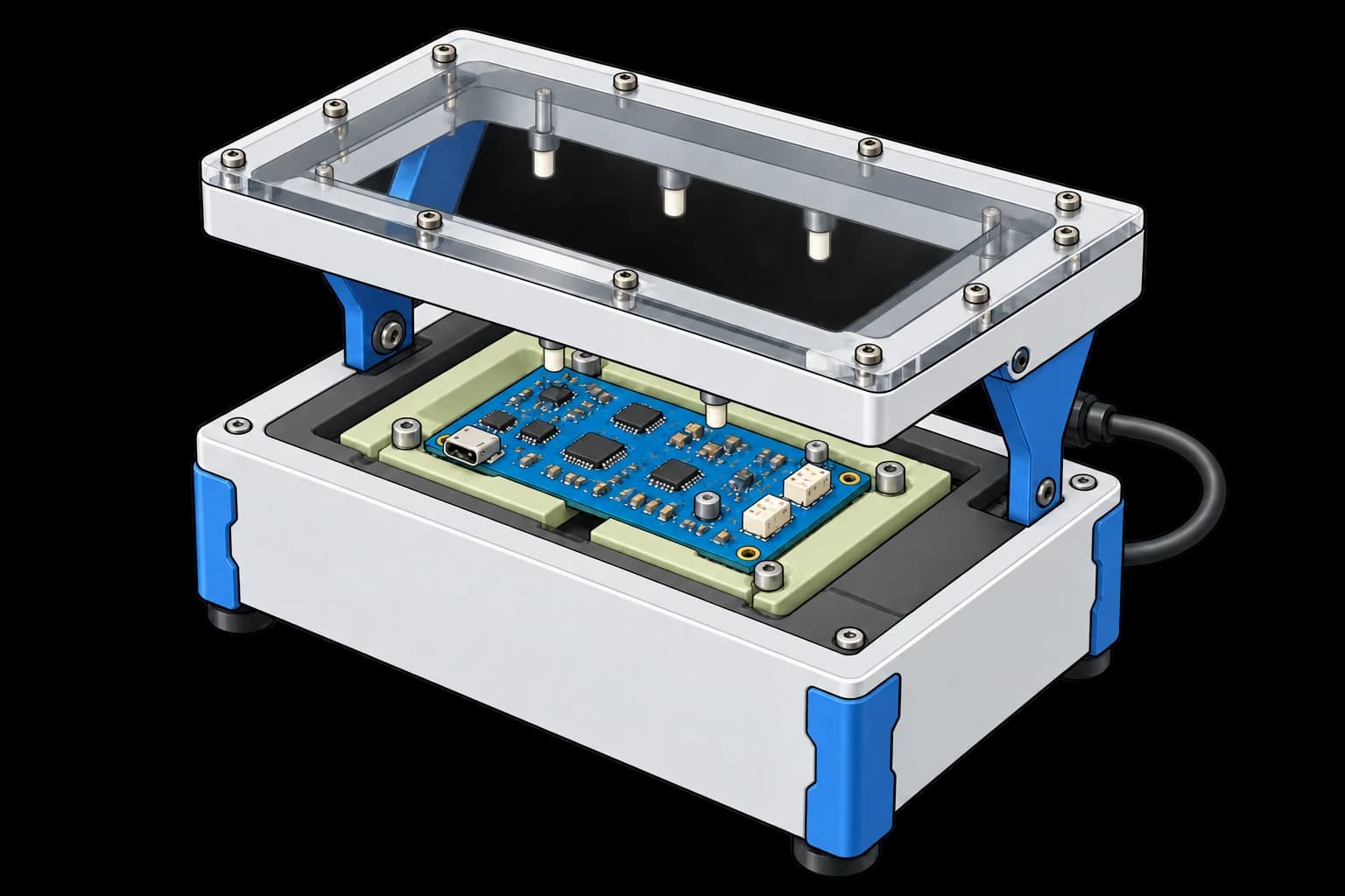
The fixture: a blue PCBA located in a support cartridge beneath a raised pressure plate. Spring probes contact test pads from below.
Hardware Components
Fixture
Four fixture topologies, in order of cost and production readiness:
- Manual clamshell / lever press: hinged top plate, operator-actuated. Cheapest, fast cycle, the NPI standard. Angled closure causes probe drag, limiting density.
- Vertical actuation press: the last few millimetres travel straight down, eliminates drag, suits HDI boards.
- Vacuum bed-of-nails: a chamber pulls the DUT onto the probes; preferred when the top must stay clear or for dual-sided access. Higher build cost, and the chamber pressure doubles as a seating check.
- Pneumatic clamshell: air-cylinder closure, consistent force, automation-ready for production lines.
Probe vendors: Ingun, Feinmetall, Everett Charles Technologies, QA Technology, with cross-reference tables between them. Production designs use 100 mil (2.54 mm pitch) probes on through-hole and standard pads and 50 mil probes for fine pitch. Tip styles (spear, crown, cup, flat, serrated) are chosen per pad finish.
Instrument Suite
A programmable FCT bench: a Rigol DP832-class triple-output supply or Keithley 2230 for Vin, an NI cDAQ chassis with analog input, analog output and DIO modules (or a USB DAQ at lower channel counts) for rails, stimulus and loopback, a USB-serial bridge for the firmware test mode, and photodiodes on the LEDs. All of it speaks SCPI, VISA or a vendor Python API from the test computer.
Safety Interlocks
- Lid-close switch wired to the e-stop bus and read by the setup phase
- Vacuum pressure sensor on the chamber to confirm the DUT is seated before power applies
- Fuse and hardware overcurrent cutoff on the Vin rail, independent of the software limits
- Two-hand buttons or a light curtain for high-force or automated fixtures
Custom Firmware
The DUT firmware exposes a production test mode triggered by a fixture-pulled GPIO. In this mode, the firmware reports raw ADC readings over UART, toggles GPIOs on command, enters stop mode on request, and disables sleep timers that would interrupt the test. Production firmware ships with this mode compiled in but locked behind the fixture pin, so the shipped unit does not expose the test interface.
Test Procedure
Overview
After scanning the DUT barcode and closing the lid, the procedure runs:
- Setup: confirm the lid interlock and the vacuum seating, record the fixture identity on the run.
- Ramp Vin with a soft start, capture inrush, check every rail and the 3V3 ripple.
- Enter the firmware test mode, read firmware version and hardware revision.
- In parallel: GPIO loopback on 32 channels, ADC linearity sweep, operator checks with photodiode backing.
- Command stop mode and measure sleep current.
- Teardown: Vin off before the lid opens.
Why TofuPilot Framework?
TofuPilot Framework is a YAML + Python test framework built for hardware manufacturing. Instead of writing all your test logic, measurements, and limits inside Python code, you describe what the test does in a procedure.yaml file, and how in small Python phase files. The framework handles:
- Automatic Python environment management (via
uv) - Operator UI (no frontend code needed)
- Measurement validation and live charts
- Process isolation between phases and equipment plugs
Project Structure
The plugs are mocks: the supply synthesizes the inrush capture, the DAQ loops the GPIOs back, the DUT answers with a 12-bit ADC that carries a small gain error for the linearity phase to find. Run it with tofupilot run . --no-tui --no-kiosk --json --ui-values ui.json, or drop --ui-values to answer the operator switches yourself. You can find the full source on GitHub.
The Procedure File
This is the exact file the template ships, verified end to end with the CLI:
procedure.yaml258 lines
name: Functional Test Fixtureversion: 0.1.0description: Powers a PCBA on a pogo-pin fixture with a soft-start ramp, checks rails and inrush, talks to the firmware test mode, exercises GPIO and ADC, records operator checks, and measures stop-mode current.unit: auto_identify: true serial_number: description: "Scan the board data-matrix" placeholder: "UAUT-00000" pattern: "^UAUT-\\d{5}$" default_value: "UAUT-04829" part_number: default_value: "PCB-MAIN-V2" metadata: firmware_version: description: "Reported by the DUT over UART"plugs: - name: Fixture Supply description: Programmable DC supply on Vin with inrush capture (mock) python: plugs.psu:FixtureSupply key: psu - name: Fixture DAQ description: Rail sense, 32-channel GPIO loopback, AWG stimulus, LED photodiodes (mock) python: plugs.daq:FixtureDaq key: daq - name: DUT Serial description: Firmware test mode over the fixture UART (mock) python: plugs.dut:DutSerial key: dutsetup: - name: Fixture Check key: fixture_check python: phases.fixture_check measurements: - name: Lid Closed key: lid_closed validators: - {operator: "==", expected_value: true} - name: Vacuum key: vacuum_kpa unit: kPa description: Chamber pressure confirming the DUT is seated on the probes. validators: - {operator: "<=", expected_value: -50.0}main: - name: Power On key: power_on python: phases.power_on measurements: - name: Inrush key: inrush title: Vin ramp and input current description: 50 ms soft-start ramp to 12 V, input current sampled at 100 kS/s. x_axis: legend: Time unit: ms y_axis: - legend: Vin key: vin unit: V - legend: Input current key: iin unit: mA aggregations: - type: peak_ma unit: mA validators: - {operator: "<=", expected_value: 400.0} - type: steady_ma unit: mA validators: - {operator: ">=", expected_value: 70.0} - {operator: "<=", expected_value: 110.0} - name: 3V3 Rail key: rail_3v3 unit: V validators: - {operator: ">=", expected_value: 3.135} - {operator: "<=", expected_value: 3.465} - name: 5V Rail key: rail_5v unit: V validators: - {operator: ">=", expected_value: 4.75} - {operator: "<=", expected_value: 5.25} - name: 1V8 Rail key: rail_1v8 unit: V validators: - {operator: ">=", expected_value: 1.71} - {operator: "<=", expected_value: 1.89} - name: 3V3 Ripple key: ripple_3v3 unit: mVpp validators: - {operator: "<=", expected_value: 30.0} - name: DUT Handshake key: dut_handshake python: phases.dut_handshake depends_on: [power_on] measurements: - name: Test Mode key: test_mode validators: - {operator: "==", expected_value: true} - name: Firmware Version key: firmware_version validators: - {operator: in, expected_value: ["2.4.1"]} - name: Hardware Revision key: hardware_revision validators: - {operator: in, expected_value: ["B", "C"]} - name: GPIO Loopback key: gpio_loopback python: phases.gpio_loopback depends_on: [dut_handshake] ui: components: - key: loopback_progress type: progress label: "GPIO loopback" description: "32 channels, high and low" default_value: 0 max: 100 measurements: - name: GPIO Pass Count key: gpio_pass_count validators: - {operator: "==", expected_value: 32} - name: GPIO Failed Channels key: gpio_failed_channels description: Channels whose loopback readback did not follow the DUT drive. validators: - {operator: "==", expected_value: []} - name: Analog Linearity key: analog_linearity python: phases.analog_linearity depends_on: [dut_handshake] ui: components: - key: sweep_progress type: progress label: "ADC sweep" description: "32 stimulus steps from 0.1 V to 3.2 V" default_value: 0 max: 100 measurements: - name: ADC Sweep key: adc_sweep title: ADC reading vs fixture stimulus x_axis: legend: Stimulus unit: V y_axis: - legend: Reading key: reading unit: V aggregations: - type: gain_error_pct unit: "%" validators: - {operator: ">=", expected_value: -0.5} - {operator: "<=", expected_value: 0.5} - type: offset_mv unit: mV validators: - {operator: ">=", expected_value: -5.0} - {operator: "<=", expected_value: 5.0} - type: r2 validators: - {operator: ">=", expected_value: 0.9999} - legend: Residual key: residual unit: mV - name: Operator Checks key: operator_checks python: phases.operator_checks depends_on: [dut_handshake] ui: components: - key: instructions type: text label: "Look at the board and listen" default_value: "The status LED must be green, the fault LED must stay off, and the buzzer chirps once. Tick what you observed." - key: status_led type: switch label: "Status LED is green" required: true bind: measurements.status_led_seen - key: fault_led type: switch label: "Fault LED is off" required: true bind: measurements.fault_led_off - key: buzzer type: switch label: "Buzzer chirped once" required: true bind: measurements.buzzer_heard measurements: - name: Status LED Seen key: status_led_seen description: Operator switch, bound straight to this measurement. validators: - {operator: "==", expected_value: true} - name: Fault LED Off key: fault_led_off validators: - {operator: "==", expected_value: true} - name: Buzzer Heard key: buzzer_heard validators: - {operator: "==", expected_value: true} - name: Status LED Photodiode key: status_led_mv unit: mV validators: - {operator: ">=", expected_value: 300.0} - name: Fault LED Photodiode key: fault_led_mv unit: mV validators: - {operator: "<=", expected_value: 20.0} - name: Sleep Current key: sleep_current python: phases.sleep_current depends_on: [gpio_loopback, analog_linearity, operator_checks] measurements: - name: Stop Mode Entered key: stop_mode_entered validators: - {operator: "==", expected_value: true} - name: Sleep Current key: sleep_current unit: µA description: Stop-mode current on the low-range shunt; a floating GPIO or an ungated clock shows up here. validators: - {operator: "<=", expected_value: 15.0}teardown: - name: Power Down key: power_down python: phases.power_down measurements: - name: Vin Off key: vin_off unit: V validators: - {operator: "<=", expected_value: 0.1}Framework features to notice:
- Setup stage:
fixture_checkmust pass before any main phase runs, so an open lid or an unseated board never sees Vin. - Phase DAG:
gpio_loopback,analog_linearityandoperator_checksall depend ondut_handshakeand on nothing else;sleep_currentdepends on all three. The framework orders them from the graph, and a failed handshake skips the whole branch. - Progress components: the two sweeps declare a
progresscomponent and update it from Python withui.<key> = value, so the operator sees the 32 channels and the 32 steps advance. - Bound operator switches: the three switches carry
bind: measurements.*; the operator's answers land as boolean measurements validated== true, andui.jsonpre-bakes them for unattended runs. The two photodiode measurements sit next to them so the operator's word is backed by a number. - JSON measurement:
gpio_failed_channelsrecords the list of failed channels and validates it against an empty list, which keeps the exact failing pins on a failed run instead of only a count.
Fixture Check
The setup phase reads the interlock and the chamber pressure, and stamps the fixture identity, cycle count and line onto the run metadata, so probe wear can be trended per fixture later:
def fixture_check(measurements, run, log): """Setup: lid interlock and DUT seating before any power is applied.""" run.metadata["fixture_id"] = "FIX-07" run.metadata["fixture_cycles"] = 18420 run.metadata["line"] = "SMT-2" measurements.lid_closed = True measurements.vacuum_kpa = -62.0 log.info("Fixture FIX-07 closed, DUT seated")Power On
The supply ramps Vin over 50 ms and returns the input current sampled at 100 kS/s. The capture lands in a multi-dimensional measurement with two y-axes; the peak and the settled mean are computed in the phase and validated in YAML:
phases/power_on.py21 lines
import numpy as npRAMP_MS = 50.0def power_on(measurements, psu, daq, log): t_ms, vin, iin = psu.ramp_to(12.0, RAMP_MS) iin = np.asarray(iin) settled = np.asarray(t_ms) > 150.0 measurements.inrush.x_axis = t_ms measurements.inrush.y_axis.vin = vin measurements.inrush.y_axis.iin = iin.tolist() measurements.inrush.y_axis.iin.aggregations.peak_ma = float(iin.max()) measurements.inrush.y_axis.iin.aggregations.steady_ma = float(iin[settled].mean()) log.info(f"Inrush peak {iin.max():.0f} mA, steady {iin[settled].mean():.0f} mA") measurements.rail_3v3 = daq.measure_rail("3v3") measurements.rail_5v = daq.measure_rail("5v") measurements.rail_1v8 = daq.measure_rail("1v8") measurements.ripple_3v3 = daq.measure_ripple_mv("3v3")GPIO Loopback
Every GPIO is driven high then low by the DUT and read back on the fixture side of the loopback jumper. The progress bar advances per channel, the failed channels are kept as a list:
from plugs.daq import GPIO_CHANNELSdef gpio_loopback(measurements, dut, daq, ui, log): failed = [] for ch in range(GPIO_CHANNELS): for level in (1, 0): dut.set_gpio(ch, level) daq.drive_gpio_from_dut(ch, level) # mock: the loopback jumper if daq.read_gpio(ch) != level: failed.append(ch) break ui.loopback_progress = int((ch + 1) / GPIO_CHANNELS * 100) measurements.gpio_pass_count = GPIO_CHANNELS - len(failed) measurements.gpio_failed_channels = failed log.info(f"GPIO loopback: {GPIO_CHANNELS - len(failed)}/{GPIO_CHANNELS} channels")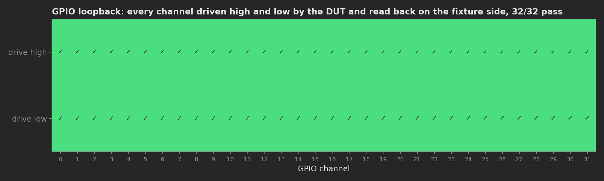
The loopback matrix of the mock run. On a real board a stuck pin shows as one red column, a solder bridge between neighbours as two.
Analog Linearity
The fixture AWG steps the stimulus from 0.1 V to 3.2 V and the firmware reports the ADC code at each step. A least-squares fit gives gain, offset and R²; the readings and the residuals both go into the chart:
phases/analog_linearity.py26 lines
import numpy as npfrom plugs.dut import ADC_BITS, ADC_FS_Vfrom utils.linearity import fit_linearitySTEPS_V = np.linspace(0.1, 3.2, 32)def analog_linearity(measurements, dut, daq, ui, log): readings = [] for i, v in enumerate(STEPS_V): daq.set_stimulus(float(v)) code = dut.read_adc(float(v)) readings.append(code / (2**ADC_BITS - 1) * ADC_FS_V) ui.sweep_progress = int((i + 1) / STEPS_V.size * 100) gain, offset_mv, r2 = fit_linearity(STEPS_V, readings) residual_mv = ((np.asarray(readings) - (gain * STEPS_V + offset_mv / 1000.0)) * 1000.0).tolist() log.info(f"ADC gain {gain:.4f}, offset {offset_mv:.1f} mV, R² {r2:.5f}") measurements.adc_sweep.x_axis = STEPS_V.tolist() measurements.adc_sweep.y_axis.reading = readings measurements.adc_sweep.y_axis.residual = residual_mv measurements.adc_sweep.y_axis.reading.aggregations.gain_error_pct = (gain - 1.0) * 100.0 measurements.adc_sweep.y_axis.reading.aggregations.offset_mv = offset_mv measurements.adc_sweep.y_axis.reading.aggregations.r2 = r2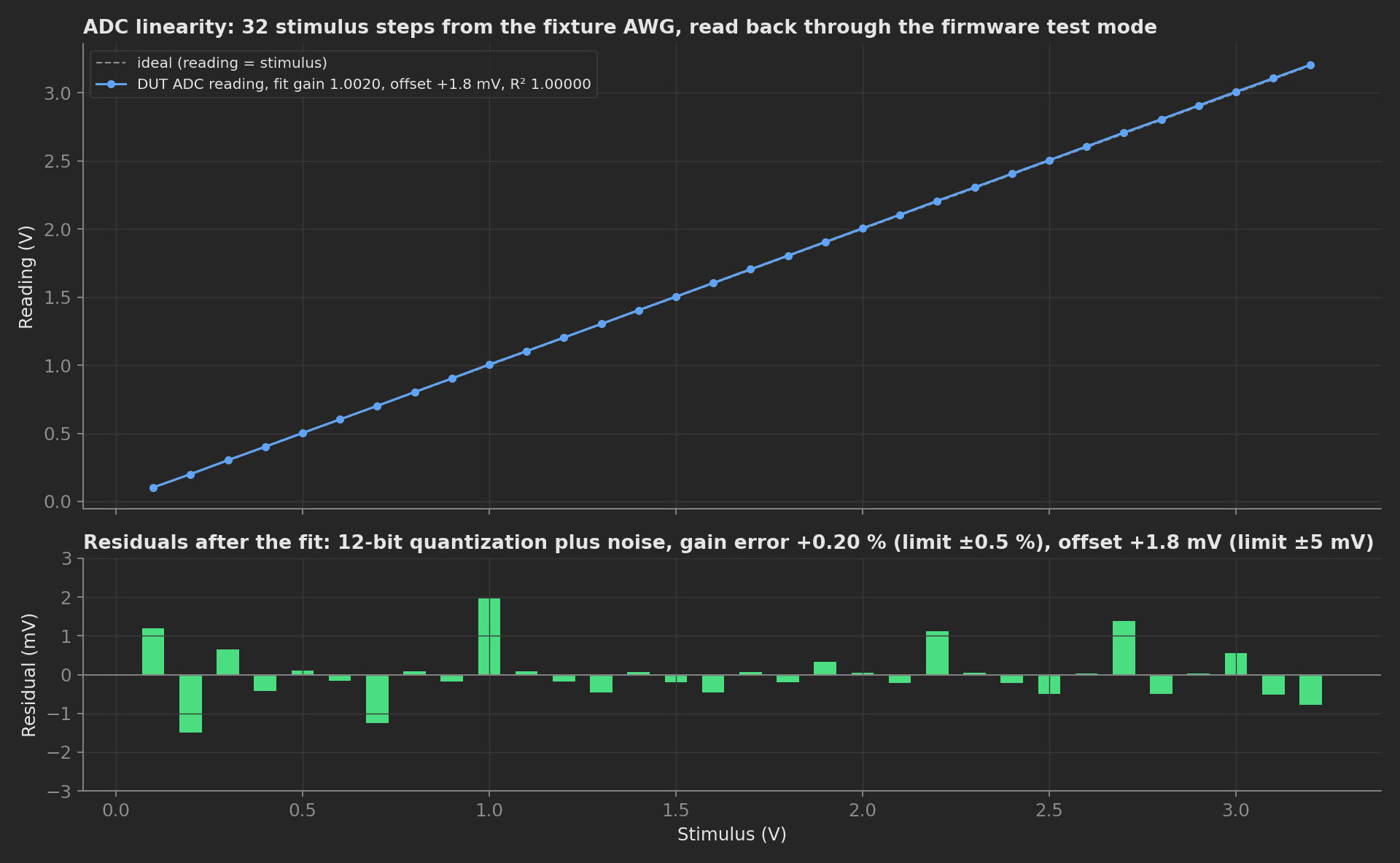
The mock DUT carries a +0.2 % gain error and a 2 mV offset on purpose; the fit finds both, well inside the ±0.5 % and ±5 mV limits, and the residuals are the 12-bit quantization plus noise.
One plug boundary to know: plug method arguments cross a process boundary as JSON, so a phase passes plain values between plugs (the stimulus voltage here), never a plug object.
Operator Checks
The fixture cannot cheaply tell a green LED from a red one or hear the buzzer, so the operator does, through three switches bound to boolean measurements. The phase adds the photodiode readings next to them:
def operator_checks(measurements, daq, log): """Photodiode readings back the operator's checklist with numbers.""" measurements.status_led_mv = daq.photodiode_mv("status_green") measurements.fault_led_mv = daq.photodiode_mv("fault_red") log.info("LED photodiodes read; operator switches recorded through their bindings")For unattended runs the answers come from ui.json, keyed by phase and component:
{ "operator_checks": { "status_led": true, "fault_led": true, "buzzer": true }}Sleep Current
With all three branches passed, the DUT is commanded into stop mode and the supply's low-range shunt reads the current. The 15 µA limit sits at three times the datasheet typical; a floating GPIO or a clock left running shows as a multiple of it:
def sleep_current(measurements, dut, psu, log): measurements.stop_mode_entered = dut.enter_stop_mode() ua = psu.measure_sleep_current_ua() log.info(f"Stop-mode current {ua:.1f} uA") measurements.sleep_current = uaMock Plugs
The supply mock builds the inrush trace from a 470 µF bulk capacitor charging at the ramp's dV/dt plus the regulator load starting up; the DUT mock applies a 1.0018 gain and a 2.1 mV offset before quantizing to 12 bits. Both carry the method surface a pyvisa supply and a pyserial test-mode client need to implement:
plugs/dut.py35 lines
import numpy as npADC_FS_V = 3.3ADC_BITS = 12class DutSerial: def __init__(self): self._rng = np.random.default_rng(3) self._test_mode = False self._gain = 1.0018 # ADC gain error the linearity phase must catch self._offset_v = 0.0021 print("DUT UART open at 115200") def enter_test_mode(self): self._test_mode = True return True def firmware_version(self): return "2.4.1" def hardware_revision(self): return "C" def set_gpio(self, channel, level): return True def read_adc(self, stimulus_v): """ADC code the firmware reports for the given fixture stimulus.""" v = float(stimulus_v) * self._gain + self._offset_v + self._rng.normal(0.0, 0.0006) code = int(round(np.clip(v, 0.0, ADC_FS_V) / ADC_FS_V * (2**ADC_BITS - 1))) return code def enter_stop_mode(self): return TrueOn a real bench, plugs/psu.py maps to a pyvisa supply with a current capture, plugs/daq.py to nidaqmx or a USB DAQ, plugs/dut.py to pyserial against the firmware test-mode protocol; the phases, measurements, and limits stay exactly the same.