
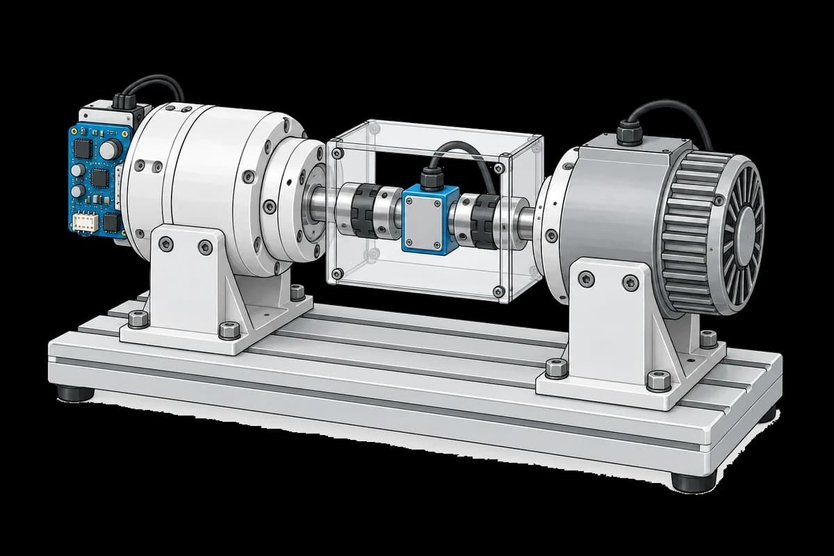
Get the complete source, dependencies and setup instructions from the template repository.
Open the source on GitHub ↗Introduction
Actuator End-of-Line Test Overview
A humanoid has thirty to forty of them: a frameless motor, a strain-wave or cycloidal reducer, an output encoder and a drive, packed into one joint module. The actuator is the part of the robot that gets built in volume, and the joint module end-of-line test is where the actuator maker or the robot maker proves each one before it goes into a leg. The vocabulary in the job postings of Figure, Apptronik, Tesla and Agility is consistent: a dyno (dynamometer) with a torque transducer and a power analyzer, driven over EtherCAT from a real-time target, measuring efficiency, stiffness, backlash, thermal limits and producing pass/fail criteria per unit.
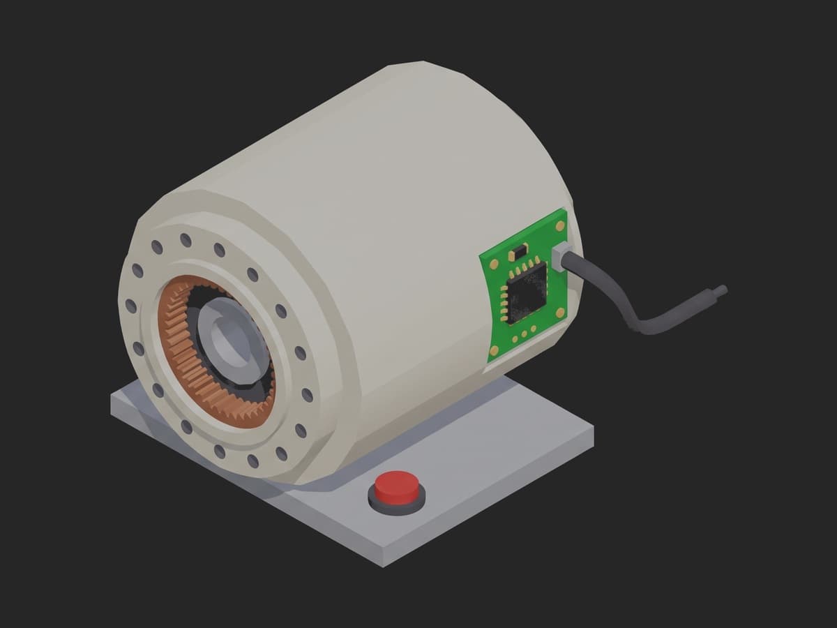
One joint actuator: the output flange with its bolt circle, the reducer's gear ring behind it, the frameless motor inside the can, the drive PCB on the back.
The numbers to build the test on are the actuator's own datasheet, cross-checked against measurement. A characterization paper on a quasi-direct-drive actuator measured the motor torque constant at 0.105 ± 0.002 Nm/A under stall with a transducer and mapped efficiency over 1838 operating points (arXiv 2202.12395); Harmonic Drive specifies the no-load running torque of its gear units after a run-in of 2 h at 2000 rpm input at 20 °C (SHD catalog); a strain-wave reducer puts two cycles of torque ripple per input revolution on the output, so a healthy unit's dominant ripple order is twice the ratio. The Kistler 4503B transducer that reads all of this is class 0.05 with ±0.03° of angle, so the bench is never the limit.
Test Purpose
The procedure records one performance fingerprint per actuator:
- Drive identity and configuration before the dyno moves: firmware, current limit, pole pairs, commutation mode
- No-load running torque through a run-in, input-referred, with its settled value limited
- Output torque constant from a locked-rotor current sweep, with the friction knee and the linearity
- Efficiency at sixteen operating points, four speeds by four torques, from shaft power over bus power
- Torque ripple over one output revolution, as a percentage of rated torque and as a dominant order
- Housing temperature at the start, after the run-in and at the end
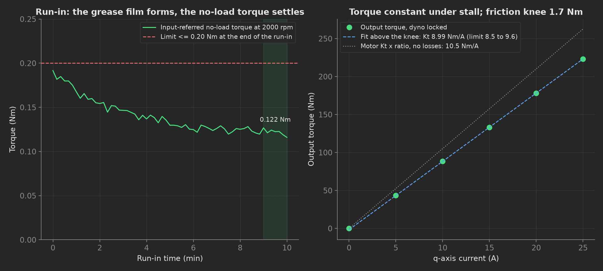
The mock actuator's first two main phases: the no-load torque settling as the grease finds its film, and the stall curve whose slope above the knee is the output-referred torque constant, 86 % of motor Kt times ratio.
The framework mechanics on show are a progress component on a time-scaled long phase, multi-dimensional measurements with derived aggregations, three curves in one measurement with the limits on one, an integer aggregation validated with == (the FFT order), string matches and JSON == on the drive before power, and setup and teardown stages around a depends_on chain.
Equipment & Setup
To run this test on an actuator line, the following are required:
- A dynamometer: a four-quadrant servo load or an eddy-current brake sized for the actuator's peak torque and speed
- An inline torque transducer with an angle output, class 0.1 or better
- A power analyzer on the DC bus
- A real-time target running the actuator's EtherCAT drive
- The Device Under Test (DUT): an assembled joint actuator with its production firmware
- A TofuPilot Framework procedure to sequence the dyno, compute the derived numbers and validate the limits
- The TofuPilot Dashboard to trend Kt, efficiency and ripple across actuators and lots
Hardware Components
Dynamometer and Transducer
Magtrol builds frameless-motor and actuator benches from a WB eddy-current dynamometer, a TM 300 inline torque transducer and a custom fixture; a servo motor on a second drive makes a four-quadrant load that can also back-drive the actuator. The Kistler 4503B is the reference transducer: dual range 0.2 to 5000 Nm, class 0.05, angle to ±0.03°, 10 kHz bandwidth; HBM's T40B is the alternative at 0.1 % of full scale. Figure's test-development posting names "analog torque cells (HBM)" and "high-resolution absolute encoders (BiSS-C)" on a Speedgoat target with Elmo and Kollmorgen drives; that is the bench this template models.
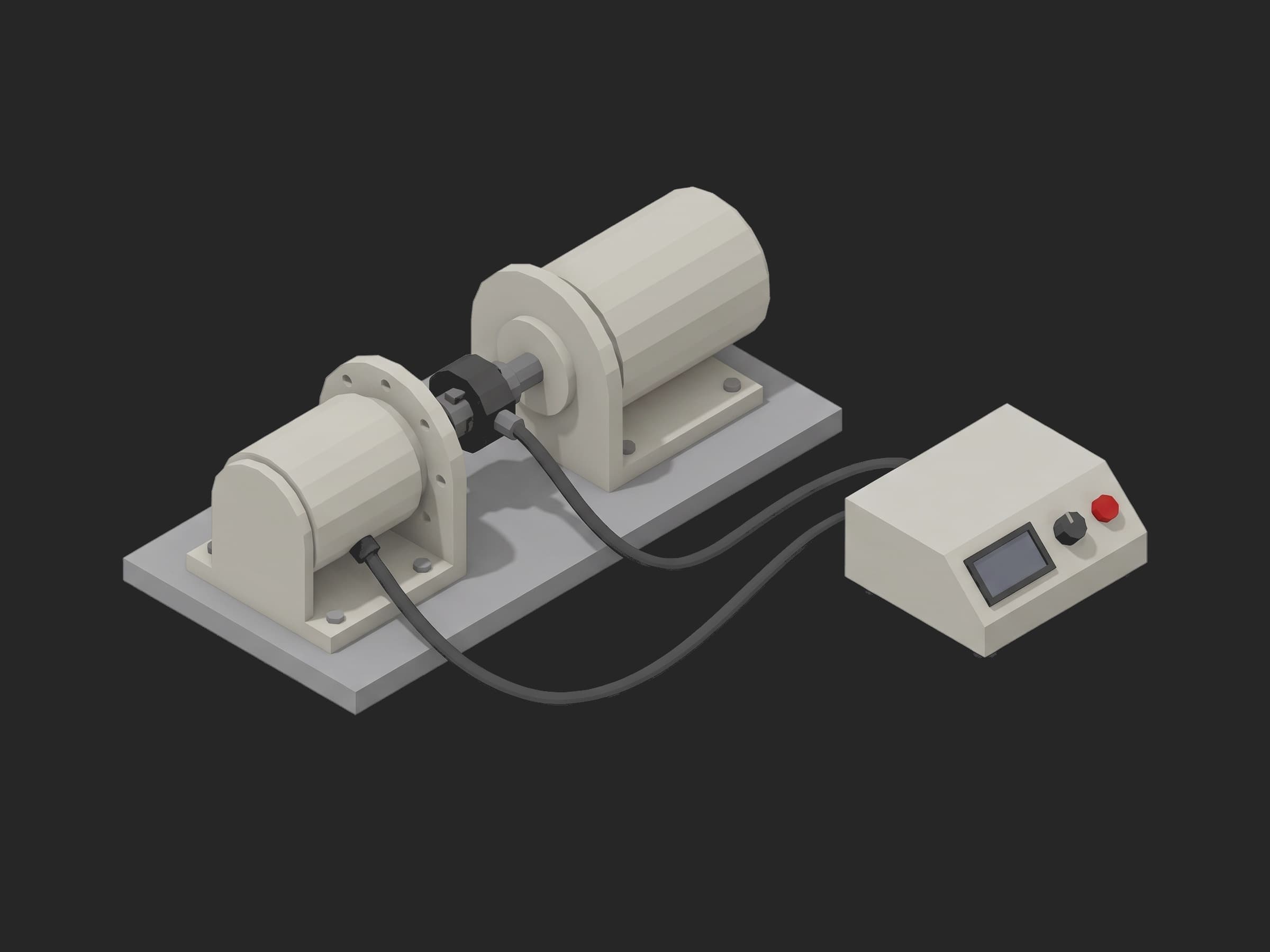
A single-axis station: the actuator in its bracket, the transducer between it and the load, the drive and the analyzer in the instrument on the right.
Drive and Bus
The actuator's own EtherCAT drive commands q-axis current for the stall sweep and speed for the map; the bus power analyzer reads the electrical input. An Apptronik posting lists "peak current, thermal limits" and "motor and encoder calibration" among the things the actuation test engineer owns; the drive configuration is read before the dyno moves because a wrong pole-pair count or current limit runs, produces torque numbers, and produces the wrong ones.
Where the Limits Come From
No standard specifies an actuator end-of-line test. GB/T 35089-2018 gives a bench method for robot precision reducers and GB/T 30819-2024 covers harmonic reducers for robots; IEC 60034-1 gives the motor's thermal classes; ISO 9283 tests the assembled robot. The limits in this template are the actuator's datasheet and the pack maker's own:
| Test | Limit | Basis |
|---|---|---|
| No-load running torque | ≤ 0.20 Nm input-referred at 2000 rpm, after run-in | reducer datasheet convention (value after 2 h at 2000 rpm) |
| Output torque constant | 8.5 to 9.6 Nm/A | motor Kt 0.105 × ratio 100 × locked-rotor efficiency 0.81 to 0.91 |
| Stall linearity | ≤ 2 % | transducer class 0.05, the rest is the actuator |
| Friction knee | ≤ 3 Nm | reducer static friction at the output |
| Efficiency at rated | ≥ 72 % | datasheet 80 % at 60 Nm / 30 rpm, minus tolerance |
| Efficiency map minimum | ≥ 50 % | light-load corner of the map |
| Torque ripple | ≤ 3 % of rated p-p | pack maker's spec; vendor guidance quotes 0.5 to 2 % |
| Dominant ripple order | == 200 | 2 × ratio for a strain-wave reducer |
The vendor-article figures that circulate ("65 to 80 % efficiency", "15 to 30 minutes per joint") are guidance without test data; the datasheet and the measured Kt are the anchors.
Test Procedure
Overview
The procedure maps the test onto the framework's three stages. The drive readback lives in setup: so no torque number is recorded on a mis-configured drive. Parking lives in teardown: so the dyno unloads and the drive disables whatever happened.
- Setup: firmware, drive configuration, housing temperature.
- Main: run-in at 2000 rpm input, no-load torque curve, settled value.
- Main: locked-rotor current sweep, Kt, friction knee, linearity.
- Main: sixteen-point efficiency map.
- Main: one revolution at 3 rpm under load, ripple and dominant order.
- Teardown: unload, disable, temperature.
Every metric validates against limits declared in procedure.yaml, and results stream to TofuPilot for trending.
Why TofuPilot Framework?
TofuPilot Framework is a YAML + Python test framework built for hardware manufacturing. Instead of writing all your test logic, measurements, and limits inside Python code, you describe what the test does in a procedure.yaml file, and how in small Python phase files. The framework handles:
- Automatic Python environment management (via
uv) - Operator UI (no frontend code needed)
- Measurement validation and live charts
- Process isolation between phases and equipment plugs
Project Structure
You can find the full source on GitHub. The ActuatorBench plug is a mock of the dyno, the transducer, the power analyzer and the drive together, synthesizing a healthy actuator on datasheet values, so the procedure runs end-to-end without a bench or an actuator connected. The run-in is time-scaled: the mock returns the ten minutes in one call.
tofupilot run .For CI or bench automation, the same run executes headless:
tofupilot run . --no-tui --no-kiosk --jsonThe Procedure File
procedure.yaml declares the unit, the bench plug, and the three stages with every measurement and limit:
procedure.yaml · 180 lines
name: Actuator End-of-Line Dyno Testversion: 0.1.0description: End-of-line dynamometer test of a humanoid joint actuator (frameless motor, 100:1 harmonic reducer, output encoder). Drive identity and configuration, time-scaled run-in with the no-load running torque, output torque constant under stall, sixteen-point efficiency map, torque ripple with order tracking over one revolution.unit: auto_identify: true serial_number: description: "Scan the actuator housing label" placeholder: "ACT-HIP-000000" pattern: "^ACT-[A-Z]{3}-\\d{6}$" default_value: "ACT-HIP-004812" part_number: default_value: "ACT-R100-60NM" batch_number: default_value: "WK-2026-37"plugs: - name: Actuator Bench description: "Four-quadrant dyno, inline torque transducer with angle, bus power analyzer, EtherCAT drive (mock, one plug per bench)" python: plugs.actuator_bench:ActuatorBench key: benchsetup: - name: Identify key: identify python: phases.identify measurements: - name: Firmware Version key: firmware_version validators: - {operator: matches, expected_value: "^3\\.\\d+\\.\\d+$"} - name: Drive Config key: drive_config description: Current limit, pole pairs, commutation mode and brake setting as one object; a wrong pole-pair count runs and produces numbers, all of them wrong. validators: - operator: "==" expected_value: current_limit_a: 30 pole_pairs: 21 commutation: sincos brake: none - name: Temperature Start key: temperature_start_c unit: °C validators: - {operator: ">=", expected_value: 18.0} - {operator: "<=", expected_value: 28.0}main: - name: Run In key: run_in python: phases.run_in timeout: 30m ui: components: - key: run_in_progress type: progress label: "Run-in at 2000 rpm input" description: "10 min unloaded, no-load torque logged every 10 s" default_value: 0 max: 100 measurements: - name: No-Load Torque key: no_load title: Input-referred no-load running torque during the run-in x_axis: legend: Time unit: min y_axis: - legend: Torque key: torque unit: Nm aggregations: - type: final_nm unit: Nm validators: - {operator: "<=", expected_value: 0.20} - type: settle_pct unit: "%" - name: Temperature After Run-In key: temperature_after_run_in_c unit: °C validators: - {operator: "<=", expected_value: 45.0} - name: Torque Constant key: torque_constant python: phases.torque_constant depends_on: [run_in] measurements: - name: Stall key: stall title: Output torque against q-axis current, dyno locked x_axis: legend: Current unit: A y_axis: - legend: Torque key: torque unit: Nm aggregations: - type: kt_nm_per_a unit: Nm/A validators: - {operator: ">=", expected_value: 8.5} - {operator: "<=", expected_value: 9.6} - type: linearity_pct unit: "%" validators: - {operator: "<=", expected_value: 2.0} - type: friction_knee_nm unit: Nm validators: - {operator: "<=", expected_value: 3.0} - name: Efficiency Map key: efficiency_map python: phases.efficiency_map depends_on: [torque_constant] timeout: 10m measurements: - name: Efficiency key: efficiency title: Efficiency at sixteen operating points, four speeds by four torques x_axis: legend: Point y_axis: - legend: Speed key: speed unit: rpm - legend: Torque key: torque unit: Nm - legend: Efficiency key: efficiency unit: "%" aggregations: - type: at_rated_pct unit: "%" validators: - {operator: ">=", expected_value: 72.0} - type: min_pct unit: "%" validators: - {operator: ">=", expected_value: 50.0} - name: Torque Ripple key: torque_ripple python: phases.torque_ripple depends_on: [efficiency_map] measurements: - name: Ripple key: ripple title: Torque over one output revolution at 3 rpm under 30 Nm x_axis: legend: Angle unit: ° y_axis: - legend: Torque key: torque unit: Nm aggregations: - type: pp_pct_rated unit: "%" validators: - {operator: "<=", expected_value: 3.0} - type: dominant_order validators: - {operator: "==", expected_value: 200}teardown: - name: Park key: park python: phases.park measurements: - name: Temperature End key: temperature_end_c unit: °C validators: - {operator: "<=", expected_value: 60.0}Framework features to notice:
- Progress on a long phase. The run-in declares a
progresscomponent and a 30 minutetimeout; the phase writesui.run_in_progressand the operator sees where the run is. The mock returns the ten minutes in one call. - Derived aggregations. The stall curve records six torque points; the pass/fail lives on
kt_nm_per_a,linearity_pctandfriction_knee_nm, all computed in Python from the fit and named in the YAML with their own limits. - Three curves, limits on one. The efficiency measurement records speed, torque and efficiency per point;
at_rated_pctandmin_pctcarry the limits. - An FFT order as an integer
==.dominant_order == 200is a physical signature: the wave generator of a 100:1 strain-wave reducer. A bearing defect or a damaged flexspline moves it. - Drive readback before power.
drive_configcompares four registers as one object;firmware_versionvalidates withmatches.
Identify
The setup phase reads the drive's identity and configuration, the housing temperature, and stamps the reducer ratio and the encoder resolution onto the unit metadata:
def identify(measurements, bench, unit, log): """Setup: EtherCAT link up, firmware and drive configuration read before the dyno moves. A drive with the wrong pole-pair count or current limit would produce plausible torque numbers at the wrong operating point.""" ident = bench.drive_identify() measurements.firmware_version = ident["firmware"] measurements.drive_config = bench.drive_config() measurements.temperature_start_c = bench.temperature_c() unit.metadata["reducer_ratio"] = ident["ratio"] unit.metadata["encoder_bits"] = ident["encoder_bits"] log.info(f"Actuator {unit.serial_number}: fw {ident['firmware']}, ratio {ident['ratio']}:1, {ident['encoder_bits']}-bit output encoder, {measurements.temperature_start_c} C")Run In
Ten minutes unloaded at 2000 rpm input, the no-load torque logged every 10 s. The value at the end is the one the reducer maker's datasheet is written against; the curve is recorded for the trend, and the percentage it settled by is an aggregation without a limit:
phases/run_in.py · 23 lines
import numpy as npfrom utils.recipe import RUN_IN_INPUT_RPM, RUN_IN_MINUTESdef run_in(measurements, bench, ui, log): """Unloaded run-in at 2000 rpm input. The no-load running torque is only meaningful after the grease has redistributed, which is why the reducer maker specifies it after a run; the value at the end of the run is the one with a limit, the curve is there for the trend.""" bench.enable() cap = bench.run_in(RUN_IN_INPUT_RPM, RUN_IN_MINUTES) t = np.array(cap["time_s"]) torque = np.array(cap["torque_nm"]) ui.run_in_progress = 100 final = float(torque[t >= t[-1] - 60.0].mean()) measurements.no_load.x_axis = (t / 60.0).round(2).tolist() measurements.no_load.y_axis.torque = cap["torque_nm"] measurements.no_load.y_axis.torque.aggregations.final_nm = final measurements.no_load.y_axis.torque.aggregations.settle_pct = float(100.0 * (torque[:3].mean() - final) / torque[:3].mean()) measurements.temperature_after_run_in_c = bench.temperature_c() log.info(f"No-load torque {torque[0]:.3f} -> {final:.3f} Nm input-referred over {RUN_IN_MINUTES:.0f} min, {measurements.temperature_after_run_in_c} C")Torque Constant
Dyno locked, q-axis current stepped from 0 to 25 A, output torque from the transducer at each step. Below the friction knee the reducer's static friction eats the torque; the fit above 10 A gives the output-referred torque constant, and the intercept gives the knee:
phases/torque_constant.py · 24 lines
import numpy as npfrom utils.recipe import KT_CURRENT_STEPS_A, KT_OUTPUT_EXPECTEDdef torque_constant(measurements, bench, log): """Dyno locked, q-axis current stepped, output torque read on the transducer. The slope above the friction knee is the output-referred torque constant: motor Kt times ratio times the locked-rotor efficiency of the reducer.""" torque = [bench.stall_torque_nm(i) for i in KT_CURRENT_STEPS_A] currents = np.array(KT_CURRENT_STEPS_A) t = np.array(torque) fit = currents >= 10.0 # above the friction knee slope, intercept = np.polyfit(currents[fit], t[fit], 1) resid = t[fit] - (slope * currents[fit] + intercept) linearity = float(100.0 * np.abs(resid).max() / t[fit].max()) measurements.stall.x_axis = KT_CURRENT_STEPS_A measurements.stall.y_axis.torque = t.round(3).tolist() measurements.stall.y_axis.torque.aggregations.kt_nm_per_a = float(slope) measurements.stall.y_axis.torque.aggregations.linearity_pct = linearity measurements.stall.y_axis.torque.aggregations.friction_knee_nm = float(-intercept) log.info(f"Kt {slope:.2f} Nm/A output-referred ({KT_OUTPUT_EXPECTED:.1f} before losses), linearity {linearity:.2f} %, friction knee {-intercept:.2f} Nm")Efficiency Map
Four speeds by four torques, the dyno holding each point, shaft power from the transducer over electrical power from the bus analyzer:
phases/efficiency_map.py · 26 lines
import numpy as npfrom utils.recipe import MAP_SPEEDS_RPM, MAP_TORQUES_NM, RATED_SPEED_RPM, RATED_TORQUE_NMdef efficiency_map(measurements, bench, log): """Sixteen operating points, four speeds by four torques, shaft power from the transducer over electrical power from the bus analyzer.""" speeds, torques, effs = [], [], [] for s in MAP_SPEEDS_RPM: for q in MAP_TORQUES_NM: op = bench.operating_point(s, q) speeds.append(s) torques.append(q) effs.append(100.0 * op["mech_w"] / op["elec_w"]) bench.unload() effs = np.array(effs) i_rated = [i for i, (s, q) in enumerate(zip(speeds, torques)) if s == RATED_SPEED_RPM and q == RATED_TORQUE_NM][0] measurements.efficiency.x_axis = list(range(1, len(effs) + 1)) measurements.efficiency.y_axis.speed = speeds measurements.efficiency.y_axis.torque = torques measurements.efficiency.y_axis.efficiency = effs.round(2).tolist() measurements.efficiency.y_axis.efficiency.aggregations.at_rated_pct = float(effs[i_rated]) measurements.efficiency.y_axis.efficiency.aggregations.min_pct = float(effs.min()) log.info(f"Efficiency {effs.min():.1f}..{effs.max():.1f} %, {effs[i_rated]:.1f} % at rated {RATED_TORQUE_NM:.0f} Nm / {RATED_SPEED_RPM:.0f} rpm")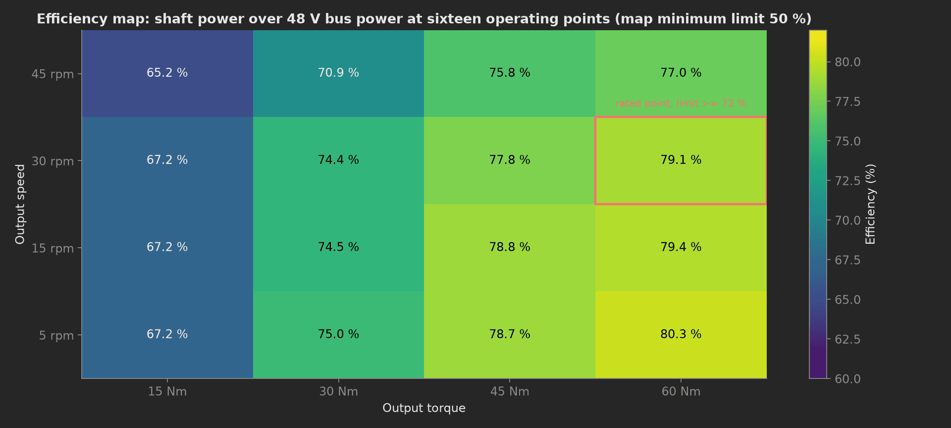
The mock actuator's map: efficiency falls toward light load as the reducer's fixed losses dominate, and slightly above rated speed. The two limits sit on the rated point and on the map's minimum.
Torque Ripple
One output revolution at 3 rpm under 30 Nm, torque against angle at 0.1°. The peak-to-peak is expressed as a percentage of rated torque; an FFT over the revolution gives the dominant order, which for a strain-wave reducer is twice the ratio, the wave generator's two lobes per input revolution:
phases/torque_ripple.py · 22 lines
import numpy as npfrom utils.recipe import RATED_TORQUE_NM, RATIO, RIPPLE_LOAD_NM, RIPPLE_SPEED_RPMdef torque_ripple(measurements, bench, log): """One output revolution at 3 rpm under 30 Nm, torque against angle. Peak-to-peak ripple as a percentage of rated torque, and the dominant order from an FFT over the revolution: a healthy harmonic drive shows 2 x ratio (the wave generator), a damaged flexspline or a bad bearing shows elsewhere.""" cap = bench.ripple_capture(RIPPLE_SPEED_RPM, RIPPLE_LOAD_NM) torque = np.array(cap["torque_nm"]) ripple = torque - torque.mean() spectrum = np.abs(np.fft.rfft(ripple)) order = int(np.argmax(spectrum[1:]) + 1) # cycles per output revolution measurements.ripple.x_axis = cap["angle_deg"] measurements.ripple.y_axis.torque = cap["torque_nm"] measurements.ripple.y_axis.torque.aggregations.pp_pct_rated = float(100.0 * (torque.max() - torque.min()) / RATED_TORQUE_NM) measurements.ripple.y_axis.torque.aggregations.dominant_order = order log.info(f"Ripple {100.0 * (torque.max() - torque.min()) / RATED_TORQUE_NM:.2f} % of rated p-p, dominant order {order} (2 x ratio = {2 * RATIO})")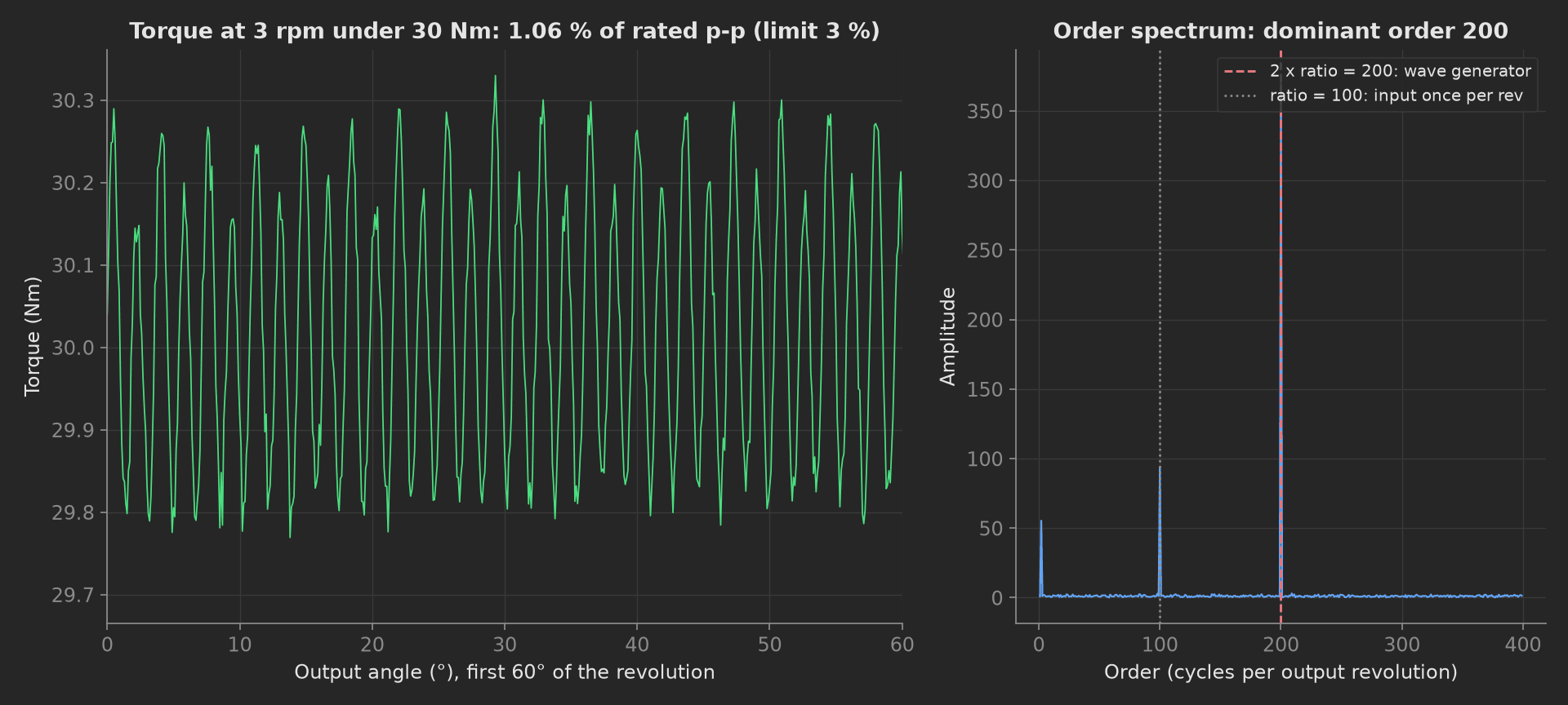
The mock's ripple: 1.06 % of rated peak-to-peak with the wave generator at order 200 and the input's once-per-revolution at order 100. A bearing defect shows at the bearing's ball-pass order, a damaged flexspline tooth at the tooth count; both move the dominant order and fail the ==.
Park
The teardown phase unloads the dyno, disables the drive and reads the housing temperature, so a hot actuator is not handed to the next station:
def park(measurements, bench, log): """Teardown: dyno unloaded, drive disabled, housing temperature read so a hot actuator is not handed to the next station.""" bench.unload() bench.disable() measurements.temperature_end_c = bench.temperature_c() log.info(f"Parked, housing at {measurements.temperature_end_c} C")Mock Plug
ActuatorBench stands in for the dyno, the transducer, the power analyzer and the drive because the readings depend on each other and plugs run in separate processes. It synthesizes a motor Kt of 0.105 Nm/A ± 0.6 %, a locked-rotor reducer efficiency of 0.86 with a 1.6 Nm friction knee, an efficiency of 0.80 at rated falling quadratically toward light load and linearly above rated speed, a no-load torque that settles from 0.19 to 0.11 Nm with a 3 minute time constant, and a ripple of 1.4 % dominated by the wave generator's second harmonic with the input's first harmonic at a quarter of it. Every method returns plain Python types because plug calls cross a JSON boundary; a measurement read back from measurements.<key> returns a proxy, so the phases keep locals for their log lines.
On a real bench, the class speaks the drive's CoE objects through pysoem or a Speedgoat model, SCPI to the power analyzer, and reads the transducer through the DAQ with its angle channel; set TIME_SCALE = 1.0 and the run-in timeout to match the reducer maker's specification. Add a backlash and stiffness phase from the companion template when the same bench carries an output-side reference encoder. The phases, measurements and limits stay the same.