
Get the complete source, dependencies and setup instructions from the template repository.
Open the source on GitHubIntroduction
ORV3 Power Supply Overview
A rack in an OCP Open Rack V3 data center has no power supply in any server. A power shelf at the bottom or the middle of the rack converts the facility's 230 to 277 Vac single phase into a 48 V class busbar that runs the height of the rack, and every compute tray hangs off that busbar with a blind-mate clip. The shelf holds a row of hot-pluggable PSU modules, 12 kW each in the high-power (HPR) generation, sharing the load in N+1 or N+2. One module that ships out of spec is not one broken server: it is a shelf that sheds load when the grid blinks, a busbar that overshoots into the trays' OVP, or a rack whose power capping is wrong because the module lies about its own current.
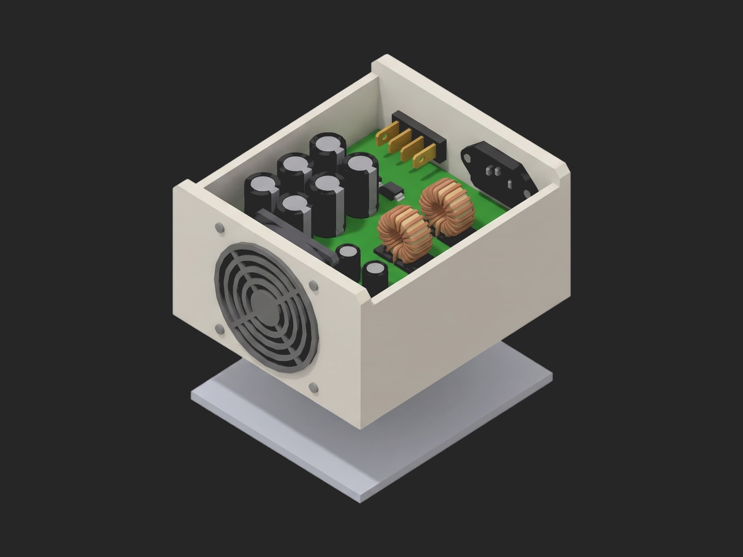
The parts this test exercises: the AC inlet and the earth path behind it, the bulk capacitors that carry the output through a mains dropout, the PFC and LLC stages that set the efficiency curve, the output blade connector, and the controller behind the Modbus port that holds the protections and the blackbox.
The OCP Open Rack V3 HPR V2 12 kW PSU module specification is unusually explicit for a production test writer. Efficiency is a floor and a peak, not a single point: at least 96.5 % from 30 to 100 % load, 94 % from 10 to 30 %, and a peak above 97.5 %, measured at 230 to 277 Vac after 30 minutes at full load with the fans running (section 4.8). Hold-up is a table: 20 ms at 100 % load, 16.67 ms at 120 %, 13.33 ms at 150 % (Table 8, section 4.17), and the AC_Loss_L signal must lead the collapse by 5 ms. Cold-start inrush is capped at 60 A RMS and 85 A peak (4.7); output ripple at 500 mVpp over 5 Hz to 100 MHz with a 20 MHz scope bandwidth (4.14); the dynamic load table asks for 70 to 130 % steps at 3 A/µs settling within 3 ms (4.15); output over-voltage must trip above 52.5 V within 200 ms, with a fast comparator at 54 V (4.22); and section 10.2 makes hipot and ground continuity a 100 % production test with a stamp on the chassis. The 80 PLUS Titanium points that the industry quotes, 90 / 94 / 96 / 91 % at 10 / 20 / 50 / 100 % load for a 230 V internal-redundant supply, all sit under the ORV3 floor. Every limit in this template is one of those rows, or says where it came from instead.
Test Purpose
The procedure records one acceptance fingerprint per module:
- Hipot leakage and ground bond with the AC source off, before anything else
- Model, firmware and serial over Modbus as one object, the reported serial compared with the scanned label, and the no-load output
- Cold-start inrush at 277 Vac closed at the 90 degree phase angle, the whole waveform, judged on its peak and its first-cycle RMS
- Efficiency at six load points at 230 and 277 Vac, each curve judged on the stair floor and the peak, with the output-current telemetry error on a third curve
- Ripple at full load, and the 70 to 130 % load step in both directions, judged on deviation and settle time
- Hold-up at 100 and 120 % load, the output traces whole, and the AC_Loss_L warning margin
- OVP, OCP, OTW and OTP trip points found in test mode, the OVP response and the OCP restart delay, and the output back in regulation afterwards
- The blackbox read at teardown, required to hold exactly the events the test caused, then cleared
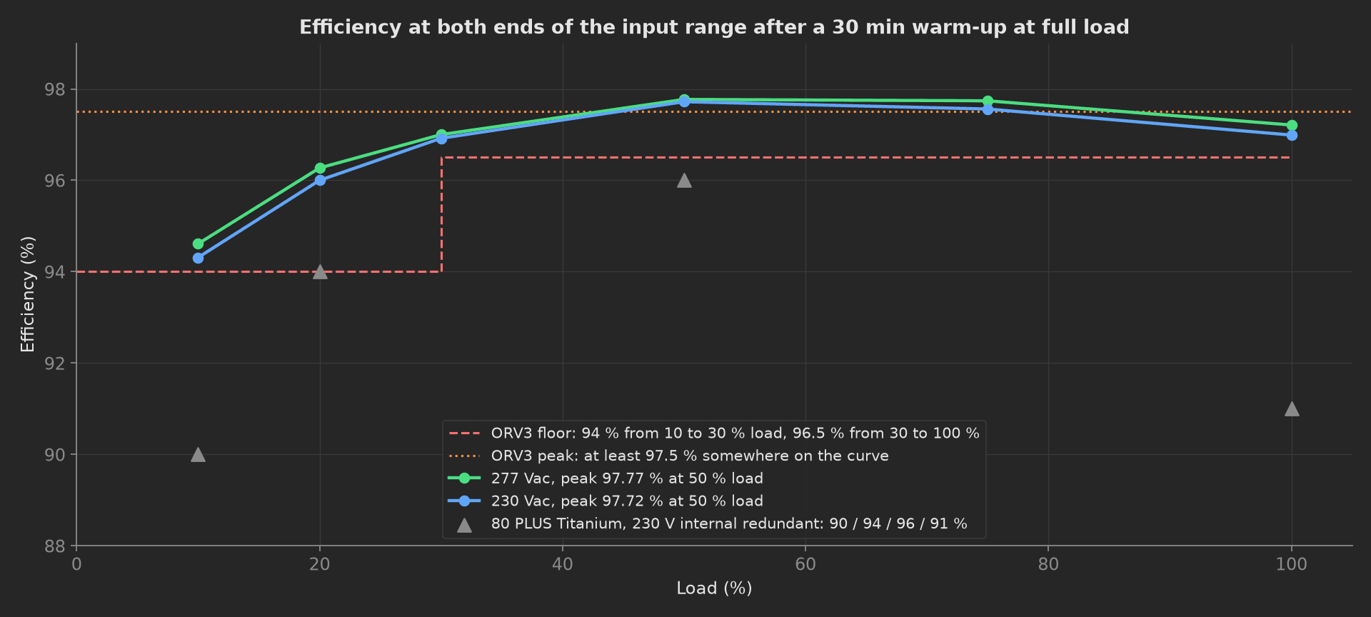
The mock module's two efficiency curves against the spec: the stair floor, the peak line, and the Titanium points that a marketing sheet would quote, all comfortably under a curve that peaks at 97.8 % at half load.
The framework mechanics on show are a setup: stage used as a safety gate, with the identity phase waiting on the hipot through depends_on; a multi-dimensional measurement with three curves and a different set of aggregations on each, validated in the YAML; four waveforms recorded whole and each judged on one or two numbers; JSON == on a whole object three times; a timeout sized for the spec's warm-up; and a teardown: that always parks the load and the source.
Equipment & Setup
To run this acceptance on a production line, the following are required:
- A programmable AC source covering 230 to 277 Vac at the module's full input current, with phase-angle start for the inrush test
- A 12 kW DC electronic load with a 3 A/µs slew and a 120 % overload range
- A power analyzer on the input and output for the efficiency sweep
- A hipot and ground-bond tester interlocked so the AC source cannot enable while it is connected
- An oscilloscope on the output with a 20 MHz bandwidth limit, and on an inrush current transformer at the input
- A USB-RS485 adapter on the module's Modbus management port
- The Device Under Test (DUT): an ORV3 HPR 12 kW PSU module with its production firmware, in a test-mode build that accepts an output trim and a thermistor override over the bus
- A TofuPilot Framework procedure to sequence the stimuli and validate the limits
- The TofuPilot Dashboard to keep the per-module evidence and the weekly Cpk the spec's section 10.1 asks for
Hardware Components
AC Source and Electronic Load
At 12 kW the input draws about 45 A at 277 Vac, and the Chroma 61512 (12 kVA, phase-angle start and stop) or a Pacific Power 3120AFX cover it; the phase-angle start is what makes the inrush test repeatable, because a contactor closed at random gives a different peak every time. On the output, a Chroma 63200A-series 12 kW module or two in parallel at 240 A, with the slew set to 3 A/µs for the load step and the CC range reaching the 130 % point. A Yokogawa WT5000 on both sides gives the 0.03 % that a Titanium-class efficiency needs to be measured rather than asserted.
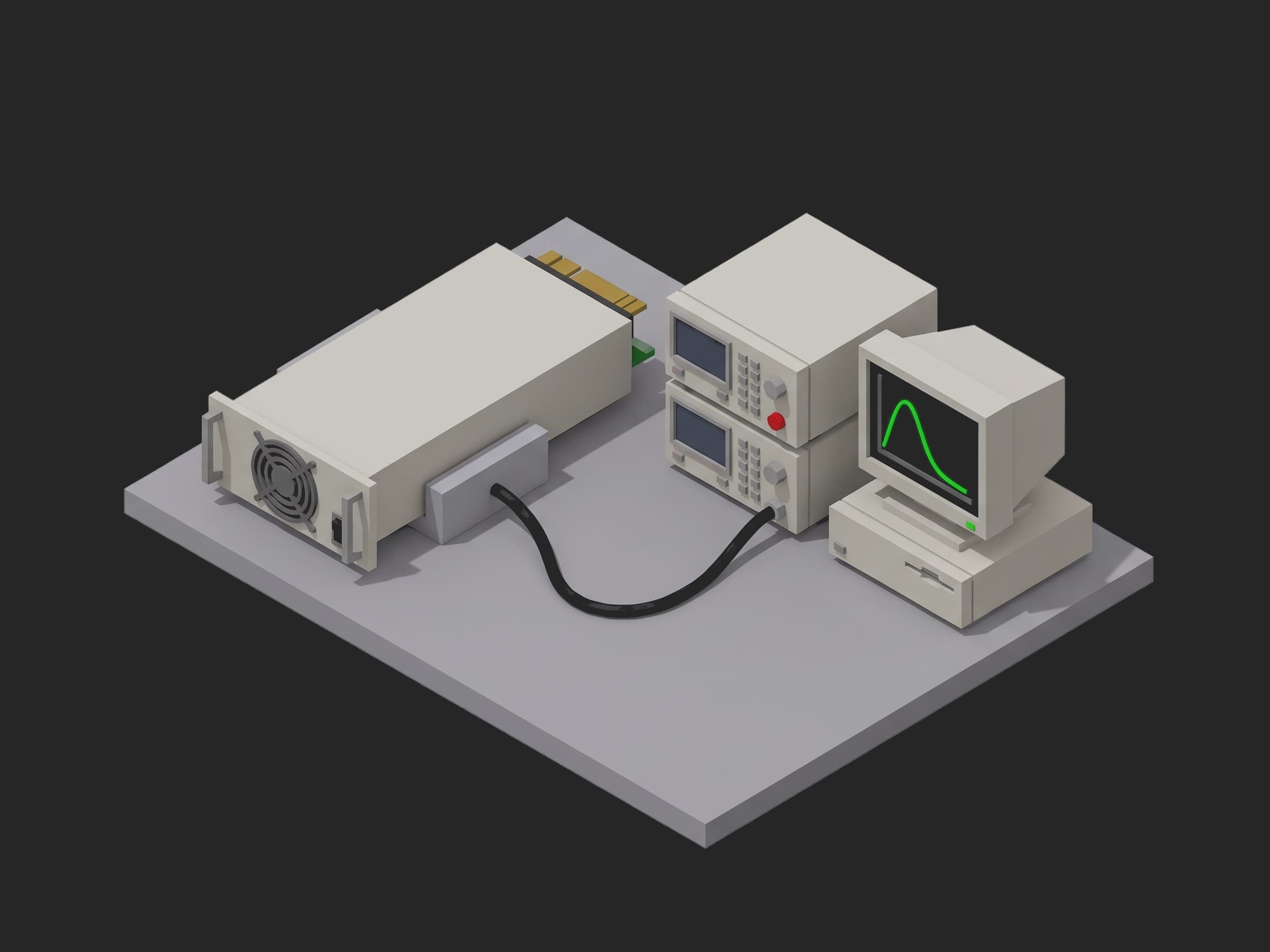
A single-fixture station: the module in a blind-mate fixture that presents the busbar clip and the Modbus pins, the source and load stacked beside it, the analyzer and scope inside the rack.
Hipot Tester and Management Bus
The Chroma 19032 does the DC withstand and the 40 A ground bond in one connection and reports leakage in microamps. The test is DC because the module's Y-capacitors would draw milliamps at 1500 Vac and hide a real fault; at 2121 Vdc a healthy unit reads tens of microamps and a pinched primary lead reads a milliamp. The management bus on the ORV3 PSU is Modbus RTU over RS-485 at 115.2 kbps, with the blackbox fault log the spec requires; the test-mode registers for output trim and thermistor override are the vendor's, and the identity, faults and blackbox registers are the spec's.
Where the Limits Come From
| Test | Limit | Basis |
|---|---|---|
| Hipot leakage | ≤ 1.0 mA at 2121 Vdc, 1 s | IEC 62368-1 routine test, 1500 Vac equivalent, basic insulation to an earthed chassis; ORV3 10.2 requires 100 % |
| Ground bond | ≤ 100 mΩ at 40 A, 2 s | IEC 62368-1 |
| Inrush | ≤ 85 A peak, ≤ 60 A RMS first cycle | ORV3 4.7 |
| Efficiency | ≥ 94 % (10 to 30 %), ≥ 96.5 % (30 to 100 %), peak ≥ 97.5 % | ORV3 4.8 |
| Iout telemetry | ≤ 2 % of reading | this line's derivation: the rack's power capping budget |
| Ripple | ≤ 500 mVpp, 20 MHz | ORV3 4.14 |
| Load step | ≤ 1.5 V deviation, settled within 3 ms | ORV3 4.15 for the stimulus and the settle time; 1.5 V keeps the overshoot under the 52.5 V OVP threshold |
| Hold-up | ≥ 20 ms at 100 %, ≥ 16.67 ms at 120 % | ORV3 Table 8 |
| AC_Loss_L lead | ≥ 5 ms | ORV3 4.17 |
| OVP | 52.5 to 54.0 V, ≤ 200 ms | ORV3 4.22 |
| Constant-current limit | 115 to 125 % of rated | ORV3: CC at 120 %; ±5 % is this line's |
| OCP restart | 9 to 11 s out of regulation | ORV3: 10 s; ±1 s is this line's |
| OTW / OTP | 85 ± 2 °C / 95 ± 2 °C, OTP − OTW ≥ 4 °C | the module's configuration; the 4 °C margin is M-CRPS 8.1.9 |
| Identity, blackbox | exact match | no tolerance applies |
Two rows in that table are traps. The 150 % hold-up line of Table 8 needs a load that sinks 18 kW, which this station does not have; the procedure tests the two rows it can and says so, rather than silently testing one. And the OVP trip on a module that regulates to 50.5 V cannot be found by raising the output externally, because the module's own stage fights the source; it is found by raising the module's set-point in test mode, which is why the DUT needs a test-mode build.
Test Procedure
Overview
The procedure maps the acceptance onto the framework's three stages. Hipot and bond live in setup: so no AC is applied to a module that fails withstand, and the identity phase depends on them so the setup stage cannot run them concurrently. The blackbox read and the park live in teardown: so the load goes to zero and the source off even when a main phase fails.
- Setup: DC withstand and ground bond, AC source off.
- Setup: first power-on, identity and serial over Modbus, no-load output.
- Main: cold-start inrush at 277 Vac, 90 degree close.
- Main: efficiency at six load points, 230 and 277 Vac, telemetry error.
- Main: ripple at full load, 70 to 130 % load step both ways.
- Main: AC loss at 100 and 120 % load, AC_Loss_L lead.
- Main: OVP, OCP, OTW and OTP in test mode, recovery.
- Teardown: blackbox checked and cleared, load off, AC off.
Every metric validates against limits declared in procedure.yaml, and results stream to TofuPilot as the per-module evidence.
Why TofuPilot Framework?
TofuPilot Framework is a YAML + Python test framework built for hardware manufacturing. Instead of writing all your test logic, measurements, and limits inside Python code, you describe what the test does in a procedure.yaml file, and how in small Python phase files. The framework handles:
- Automatic Python environment management (via
uv) - Operator UI (no frontend code needed)
- Measurement validation and live charts
- Process isolation between phases and equipment plugs
Project Structure
You can find the full source on GitHub. The PsuBench plug is a mock of the AC source, the load, the analyzer, the hipot tester, the scope and the Modbus port together, synthesizing a healthy module with Titanium-class efficiency peaking at half load, 7.2 mF of bulk capacitance, every comparator inside its window and a blackbox that records what the test does to it, so the procedure runs end-to-end without a bench or a module connected.
tofupilot run .For CI or bench automation, the same run executes headless:
tofupilot run . --no-tui --no-kiosk --jsonThe Procedure File
procedure.yaml declares the unit, the bench plug with the label serial as constructor argument, and the three stages with every measurement and limit:
procedure.yaml313 lines
name: ORV3 PSU Acceptance Testversion: 0.1.0description: Acceptance of an OCP Open Rack V3 HPR 12 kW PSU module. Hipot and ground bond before AC is applied, identity over Modbus, cold-start inrush at the 90 degree phase angle, efficiency at 230 and 277 Vac against the ORV3 floor and the Titanium points, ripple and the 70 to 130 percent load step, hold-up at 100 and 120 percent load with the AC_Loss_L lead, OVP OCP OTW and OTP trips in test mode, and a blackbox that must hold exactly what the test did before it is cleared.unit: auto_identify: true serial_number: description: "Scan the data-matrix on the module's handle" placeholder: "ORV3-12K-000000" pattern: "^ORV3-12K-\\d{6}$" default_value: "ORV3-12K-004217" part_number: default_value: "PSU-ORV3-12K-277" batch_number: default_value: "LOT-2026-38"plugs: - name: PSU Bench description: "AC source, 12 kW DC load, power analyzer, hipot tester, scope and the PSU's Modbus port (mock, one plug per bench)" python: plugs.psu_bench:PsuBench key: bench config: serial_number: "ORV3-12K-004217"setup: - name: Hipot and Ground Bond key: hipot_and_bond python: phases.hipot_and_bond measurements: - name: Hipot Leakage key: hipot_leakage_ma unit: mA description: "2121 Vdc primary to chassis for 1 s (IEC 62368-1 routine test, 1500 Vac equivalent). Y-capacitors pass nothing at DC; a healthy module leaks tens of microamps." validators: - {operator: "<=", expected_value: 1.0} - name: Ground Bond key: ground_bond_mohm unit: mΩ description: "Inlet earth pin to chassis at 40 A for 2 s." validators: - {operator: "<=", expected_value: 100.0} - name: Identify key: identify python: phases.identify depends_on: [hipot_and_bond] measurements: - name: PSU Identity key: psu_identity description: Model, firmware and management protocol as one object against the release. validators: - operator: "==" expected_value: model: PSU-ORV3-12K-277 fw: 2.4.1 protocol: modbus-rtu - name: Reported Serial key: reported_serial validators: - {operator: matches, expected_value: "^ORV3-12K-\\d{6}$"} - name: Serial Matches Label key: serial_matches_label description: The serial the module reports over Modbus is the one on its label. validators: - {operator: "==", expected_value: true} - name: Output At No Load key: vout_no_load_v unit: V validators: - {operator: ">=", expected_value: 50.0} - {operator: "<=", expected_value: 51.0}main: - name: Inrush key: inrush python: phases.inrush measurements: - name: Inrush Current key: inrush title: Cold-start inrush at 277 Vac, closed at 90 degrees x_axis: legend: Time unit: ms y_axis: - legend: Input current key: current unit: A aggregations: - type: peak_a unit: A validators: - {operator: "<=", expected_value: 85.0} - type: first_cycle_rms_a unit: A validators: - {operator: "<=", expected_value: 60.0} - name: Efficiency key: efficiency python: phases.efficiency depends_on: [inrush] timeout: 45m measurements: - name: Efficiency key: efficiency title: Efficiency and output-current telemetry across the load range x_axis: legend: Load unit: "%" y_axis: - legend: Efficiency at 277 Vac key: eff_277 unit: "%" aggregations: - type: min_30_100_pct unit: "%" validators: - {operator: ">=", expected_value: 96.5} - type: min_10_30_pct unit: "%" validators: - {operator: ">=", expected_value: 94.0} - type: peak_pct unit: "%" validators: - {operator: ">=", expected_value: 97.5} - legend: Efficiency at 230 Vac key: eff_230 unit: "%" aggregations: - type: min_30_100_pct unit: "%" validators: - {operator: ">=", expected_value: 96.5} - type: min_10_30_pct unit: "%" validators: - {operator: ">=", expected_value: 94.0} - type: peak_pct unit: "%" validators: - {operator: ">=", expected_value: 97.5} - legend: Iout telemetry error at 277 Vac key: iout_telemetry_err_pct unit: "%" aggregations: - type: max_abs_pct unit: "%" validators: - {operator: "<=", expected_value: 2.0} - name: Ripple and Load Step key: ripple_and_transient python: phases.ripple_and_transient depends_on: [efficiency] measurements: - name: Output Ripple key: ripple_mvpp unit: mVpp description: "Full load, 20 MHz bandwidth, 0.1 uF at the probe tip (spec 4.14)." validators: - {operator: "<=", expected_value: 500.0} - name: Load Step key: load_step title: Output deviation on the 70 to 130 percent load step at 3 A/us x_axis: legend: Time unit: ms y_axis: - legend: Step up key: step_up unit: V aggregations: - type: min_v unit: V validators: - {operator: ">=", expected_value: -1.5} - type: settle_ms unit: ms validators: - {operator: "<=", expected_value: 3.0} - legend: Step down key: step_down unit: V aggregations: - type: max_v unit: V validators: - {operator: "<=", expected_value: 1.5} - type: settle_ms unit: ms validators: - {operator: "<=", expected_value: 3.0} - name: Hold-Up key: hold_up python: phases.hold_up depends_on: [ripple_and_transient] measurements: - name: Hold-Up key: hold_up title: Output voltage after AC loss at 100 and 120 percent load x_axis: legend: Time after AC loss unit: ms y_axis: - legend: Output at 100 % load key: vout_100 unit: V aggregations: - type: hold_up_ms unit: ms validators: - {operator: ">=", expected_value: 20.0} - legend: Output at 120 % load key: vout_120 unit: V aggregations: - type: hold_up_ms unit: ms validators: - {operator: ">=", expected_value: 16.67} - name: AC Loss Warning Margin key: ac_loss_warning_margin_ms unit: ms description: "Time from AC_Loss_L asserting to the output leaving regulation, worst of the two loads. The rack needs 5 ms to shed load." validators: - {operator: ">=", expected_value: 5.0} - name: Protections key: protections python: phases.protections depends_on: [hold_up] measurements: - name: OVP Trip key: ovp_trip_v unit: V description: "Set-point raised in 0.1 V steps in test mode until the output latches off. Spec 4.22: trip above 52.5 V, the fast comparator at 54 V." validators: - {operator: ">=", expected_value: 52.5} - {operator: "<=", expected_value: 54.0} - name: OVP Response key: ovp_response_ms unit: ms validators: - {operator: "<=", expected_value: 200.0} - name: Constant-Current Limit key: cc_limit_a unit: A description: "Load ramped in 2 A steps until the output leaves regulation. 120 % of 237.6 A rated, +-5 % of this line's derivation." validators: - {operator: ">=", expected_value: 273.0} - {operator: "<=", expected_value: 297.0} - name: OCP Restart Delay key: ocp_restart_s unit: s description: "Time out of regulation before the module shuts down and restarts, 10 s in the spec, +-1 s here." validators: - {operator: ">=", expected_value: 9.0} - {operator: "<=", expected_value: 11.0} - name: OTW Trip key: otw_trip_c unit: °C validators: - {operator: ">=", expected_value: 83.0} - {operator: "<=", expected_value: 87.0} - name: OTP Trip key: otp_trip_c unit: °C validators: - {operator: ">=", expected_value: 93.0} - {operator: "<=", expected_value: 97.0} - name: OTP Minus OTW key: otp_minus_otw_c unit: °C description: "The warning must lead the shutdown by at least 4 C (M-CRPS 8.1.9), or the rack learns of the problem by losing the module." validators: - {operator: ">=", expected_value: 4.0} - name: Recovered After Trips key: recovered_after_trips description: Output back in regulation after the last fault is cleared. validators: - {operator: "==", expected_value: true}teardown: - name: Blackbox and Park key: blackbox_and_park python: phases.blackbox_and_park measurements: - name: Blackbox After Test key: blackbox_after_test description: "Exactly the events this test caused: two AC losses, one of each trip, no fan fault. Anything else happened on its own." validators: - operator: "==" expected_value: ac_loss: 2 ovp: 1 ocp: 1 otw: 1 otp: 1 fan: 0 - name: Blackbox After Clear key: blackbox_after_clear description: Ships empty, so the first entry the customer reads happened in their rack. validators: - operator: "==" expected_value: ac_loss: 0 ovp: 0 ocp: 0 otw: 0 otp: 0 fan: 0Framework features to notice:
setup:as a safety gate. Setup phases run concurrently unless told otherwise;identifydeclaresdepends_on: [hipot_and_bond]so the AC source cannot be enabled while the hipot tester is on the inlet.- Three curves, three aggregation sets.
efficiencycarries the 277 Vac curve, the 230 Vac curve and the telemetry error on one x-axis; the first two are judged onmin_30_100_pct,min_10_30_pctandpeak_pct, the third onmax_abs_pct. - The spec's shape, not a single number. A stair floor and a peak for efficiency, a table of hold-up times per load, a peak and an RMS for inrush: each is one aggregation with its own limit, and the whole waveform stays attached for the review.
- A whole object, compared once.
psu_identity,blackbox_after_testandblackbox_after_cleareach validate with one==; the report shows which key differed. matchesnext to==.reported_serialmust look like a serial;serial_matches_labelsays it is this module's.- A
timeoutfor the warm-up. The efficiency phase is allowed 45 minutes because the spec's 30 minute soak is part of the measurement, not overhead. teardown:always runs. Load to zero, blackbox read and cleared, source off, whatever a main phase did.
Hipot and Ground Bond
Three seconds, no AC, and the highest consequence of any step in the sequence. The setup phase forces the source off and the load to zero, applies 2121 Vdc from the shorted line and neutral to the chassis for one second, then 40 A from the inlet earth pin to the chassis for two, and stamps the withstand voltage onto the unit metadata:
from utils.recipe import GROUND_BOND_A, GROUND_BOND_DWELL_S, HIPOT_DWELL_S, HIPOT_VDCdef hipot_and_bond(measurements, bench, unit, log): """Setup: withstand and ground bond with the AC source off. A module with a pinched primary lead or a missing earth screw fails here in three seconds, before any of the 12 kW ever flows through it.""" bench.ac_off() bench.set_load_a(0.0) leak = bench.hipot_dc(HIPOT_VDC, HIPOT_DWELL_S) bond = bench.ground_bond(GROUND_BOND_A, GROUND_BOND_DWELL_S) measurements.hipot_leakage_ma = leak measurements.ground_bond_mohm = bond unit.metadata["hipot_vdc"] = HIPOT_VDC log.info(f"{unit.serial_number}: {HIPOT_VDC:.0f} Vdc for {HIPOT_DWELL_S:.0f} s leaks {leak:.3f} mA, bond {bond:.1f} mOhm at {GROUND_BOND_A:.0f} A")Identify
The first power-on, at no load, and the first Modbus transaction. The identity is compared as one object against the release; the serial the module reports is checked against the one on its label. A module carrying another unit's serial passes every electrical test and breaks the rack's inventory the day it is installed.
from utils.recipe import AC_INPUTS_Vdef identify(measurements, bench, unit, log): """Setup: first power-on at 277 Vac with no load, then the model, firmware and serial read over Modbus. The serial the PSU reports must be the one on its label: a module programmed with another unit's identity is a rack that cannot be inventoried.""" bench.ac_on(AC_INPUTS_V[-1]) identity = bench.modbus_identity() serial = bench.modbus_serial() vout = bench.vout_v() measurements.psu_identity = identity measurements.reported_serial = serial measurements.serial_matches_label = serial == unit.serial_number measurements.vout_no_load_v = vout unit.metadata["fw"] = identity["fw"] log.info(f"{identity['model']} fw {identity['fw']} reports {serial}, label {unit.serial_number}, {vout:.2f} V at no load")Inrush
The source is switched off, the load is zero, and the source closes at the 90 degree phase angle where the bulk capacitors see the full peak. The waveform is recorded whole from the inrush CT; the phase computes the peak and the RMS of the first mains cycle and attaches both as aggregations with the spec's limits.
phases/inrush.py24 lines
import numpy as npfrom utils.recipe import AC_INPUTS_V, MAINS_HZdef inrush(measurements, bench, log): """Cold start at 277 Vac closed at the 90 degree phase angle, the worst case for the bulk capacitors, on the inrush CT. Peak and the RMS of the first mains cycle, both limits from section 4.7 of the spec.""" bench.ac_off() bench.set_load_a(0.0) t_ms, i_a = bench.inrush_capture(90.0) bench.ac_on(AC_INPUTS_V[-1]) t = np.asarray(t_ms) i = np.asarray(i_a) first_cycle = i[t < 1000.0 / MAINS_HZ] peak = float(np.abs(i).max()) rms = float(np.sqrt(np.mean(first_cycle**2))) measurements.inrush.x_axis = t_ms measurements.inrush.y_axis.current = i_a measurements.inrush.y_axis.current.aggregations.peak_a = round(peak, 2) measurements.inrush.y_axis.current.aggregations.first_cycle_rms_a = round(rms, 2) log.info(f"Inrush at 90 deg: peak {peak:.1f} A, first-cycle RMS {rms:.1f} A over {len(i_a)} samples")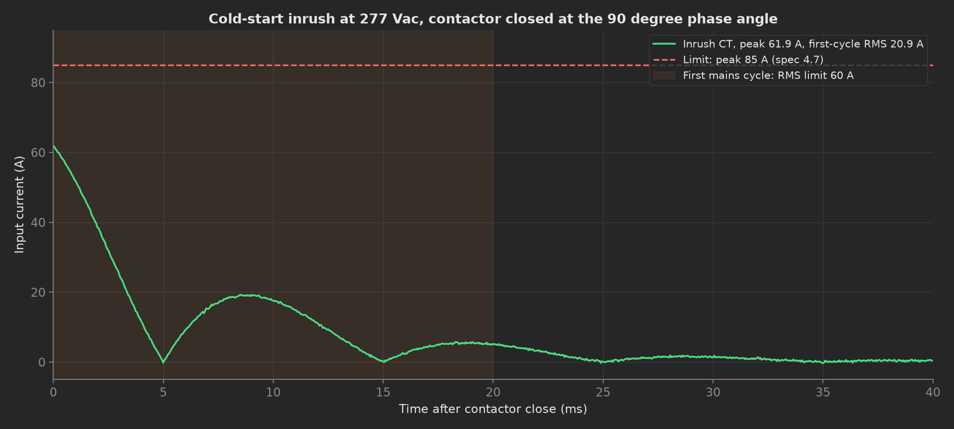
The mock module's cold start: 61.9 A on the first half-cycle, decaying with the bulk capacitor charge, 20.9 A RMS over the first cycle. A module with its NTC inrush limiter bypassed shows the same shape at twice the height.
Efficiency
Full load for the spec's 30 minutes, then six load points at each end of the input range, input and output power from the analyzer. At each point the phase also reads the output current the module reports over Modbus and records the error against the load's own reading: the rack's power capping runs on that telemetry, and a module that reports 2 % low lets the shelf oversubscribe. The mock skips the soak; the timeout is sized for the real one.
phases/efficiency.py49 lines
import numpy as npfrom utils.recipe import AC_INPUTS_V, LOAD_POINTS_PCT, RATED_A, WARM_UP_MINdef sweep(bench, vin, log): """Six load points at one input voltage: analyzer in and out, and the output current the PSU reports next to the load's own reading.""" bench.ac_on(vin) eff = [] telemetry_err = [] for pct in LOAD_POINTS_PCT: amps = pct / 100.0 * RATED_A bench.set_load_a(amps) pin, pout = bench.analyzer_pin_pout_w(pct) eff.append(100.0 * pout / pin) telemetry_err.append(100.0 * (bench.modbus_iout_a() - amps) / amps) log.info(f"{vin:.0f} Vac, {pct:3d} %: {pin:.0f} W in, {pout:.0f} W out, {eff[-1]:.2f} %, Iout telemetry {telemetry_err[-1]:+.2f} %") return np.array(eff), np.array(telemetry_err)def efficiency(measurements, bench, log): """Efficiency at both ends of the input range after the spec's 30 min warm-up at full load. The ORV3 floor is a stair (94 % below 30 % load, 96.5 % above) and a peak (97.5 %); the Titanium points sit under it.""" bench.set_load_a(RATED_A) log.info(f"Warm-up: {WARM_UP_MIN} min at {RATED_A:.0f} A (mock: instant)") curves = {} for vin in AC_INPUTS_V: curves[vin] = sweep(bench, vin, log) pts = np.array(LOAD_POINTS_PCT) low = pts < 30 high = pts >= 30 m = measurements.efficiency m.x_axis = LOAD_POINTS_PCT e277, err = curves[277.0] e230, _ = curves[230.0] m.y_axis.eff_277 = e277.round(2).tolist() m.y_axis.eff_277.aggregations.min_30_100_pct = round(float(e277[high].min()), 2) m.y_axis.eff_277.aggregations.min_10_30_pct = round(float(e277[low].min()), 2) m.y_axis.eff_277.aggregations.peak_pct = round(float(e277.max()), 2) m.y_axis.eff_230 = e230.round(2).tolist() m.y_axis.eff_230.aggregations.min_30_100_pct = round(float(e230[high].min()), 2) m.y_axis.eff_230.aggregations.min_10_30_pct = round(float(e230[low].min()), 2) m.y_axis.eff_230.aggregations.peak_pct = round(float(e230.max()), 2) m.y_axis.iout_telemetry_err_pct = err.round(2).tolist() m.y_axis.iout_telemetry_err_pct.aggregations.max_abs_pct = round(float(np.abs(err).max()), 2) log.info(f"Peak {e277.max():.2f} % at 277 Vac, {e230.max():.2f} % at 230 Vac; floor {min(e277[high].min(), e230[high].min()):.2f} % above 30 % load")Ripple and Load Step
Ripple at full load in the spec's bandwidth, then the dynamic load of section 4.15: from 70 to 130 % of rated at 3 A/µs and back. The deviation from the set-point is recorded whole in both directions; the phase finds the last sample outside the ±1 % band and reports the next one as the settle time.
phases/ripple_and_transient.py38 lines
import numpy as npfrom utils.recipe import DYN_CAPTURE_MS, DYN_LOAD_PCT, DYN_SLEW_A_PER_US, RATED_A, RIPPLE_BW_MHZ, SETTLE_BAND_Vdef settle_ms(t_ms, dev_v): """Last excursion outside the +-1 % band; settled from the next sample.""" t = np.asarray(t_ms) outside = np.where(np.abs(np.asarray(dev_v)) > SETTLE_BAND_V)[0] return float(t[outside[-1] + 1]) if len(outside) else 0.0def ripple_and_transient(measurements, bench, log): """Ripple at full load in the spec's 20 MHz bandwidth, then the dynamic load step of section 4.15 in both directions: 70 to 130 % of rated at 3 A/us. The deviation limit keeps the overshoot under the OVP threshold and the undershoot inside the regulation window.""" bench.set_load_a(RATED_A) ripple = bench.ripple_mvpp(RIPPLE_BW_MHZ) measurements.ripple_mvpp = ripple lo, hi = DYN_LOAD_PCT bench.set_load_a(lo / 100.0 * RATED_A) t_ms, up = bench.transient_capture(lo, hi, DYN_SLEW_A_PER_US) _, down = bench.transient_capture(hi, lo, DYN_SLEW_A_PER_US) bench.set_load_a(RATED_A) up_settle = settle_ms(t_ms, up) down_settle = settle_ms(t_ms, down) m = measurements.load_step m.x_axis = t_ms m.y_axis.step_up = up m.y_axis.step_up.aggregations.min_v = round(float(min(up)), 3) m.y_axis.step_up.aggregations.settle_ms = round(up_settle, 2) m.y_axis.step_down = down m.y_axis.step_down.aggregations.max_v = round(float(max(down)), 3) m.y_axis.step_down.aggregations.settle_ms = round(down_settle, 2) log.info(f"Ripple {ripple:.0f} mVpp; step {lo}->{hi} % undershoots {min(up):.2f} V, settles in {up_settle:.2f} ms; {hi}->{lo} % overshoots {max(down):+.2f} V, settles in {down_settle:.2f} ms over a {DYN_CAPTURE_MS:.0f} ms capture")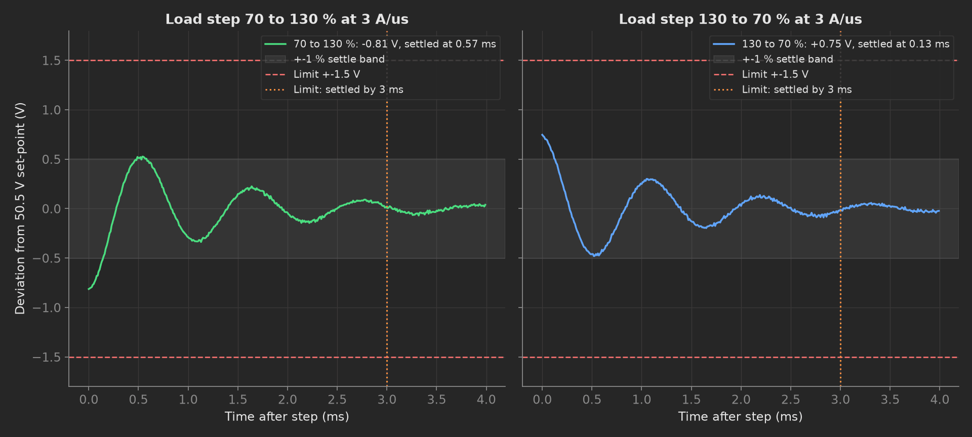
The two steps on the mock module: a 0.9 kHz loop with a 1.2 ms envelope, inside the band in well under a millisecond. The 1.5 V limit is not in the spec; it is the distance from the 50.5 V set-point to the 52.5 V OVP threshold with half a volt to spare, so a module that passes here cannot trip its own OVP on a tray hot-plug.
Hold-Up
AC removed at full load and at 120 %, the output recorded whole each time. The module regulates from its bulk capacitors until the bus reaches UVLO, then the output capacitors discharge into the load; the phase reports the time the output stayed above the regulation floor as the hold-up, and the worst margin between the AC_Loss_L assertion and the collapse as the warning the rack gets.
phases/hold_up.py31 lines
import numpy as npfrom utils.recipe import AC_INPUTS_V, HOLDUP_LOADS_PCT, RATED_A, REGULATION_LOW_Vdef hold_up(measurements, bench, log): """AC removed at full load and at 120 % (Table 8): the output must stay in regulation for 20 ms and 16.67 ms, and AC_Loss_L must lead the collapse by at least 5 ms so the rack can shed load. Hold-up is a capacitor-energy budget; a bulk capacitor from the wrong reel shows up here and nowhere else.""" margins = [] traces = {} for pct in HOLDUP_LOADS_PCT: bench.set_load_a(pct / 100.0 * RATED_A) t_ms, v, ac_loss_ms = bench.ac_loss_capture(pct) bench.ac_on(AC_INPUTS_V[-1]) t = np.asarray(t_ms) below = np.where(np.asarray(v) < REGULATION_LOW_V)[0] held = float(t[below[0]]) if len(below) else float(t[-1]) margins.append(held - ac_loss_ms) traces[pct] = (t_ms, v, held) log.info(f"AC loss at {pct} %: output above {REGULATION_LOW_V} V for {held:.1f} ms, AC_Loss_L after {ac_loss_ms:.1f} ms") m = measurements.hold_up m.x_axis = traces[100][0] m.y_axis.vout_100 = traces[100][1] m.y_axis.vout_100.aggregations.hold_up_ms = round(traces[100][2], 1) m.y_axis.vout_120 = traces[120][1] m.y_axis.vout_120.aggregations.hold_up_ms = round(traces[120][2], 1) measurements.ac_loss_warning_margin_ms = round(min(margins), 1) bench.set_load_a(RATED_A)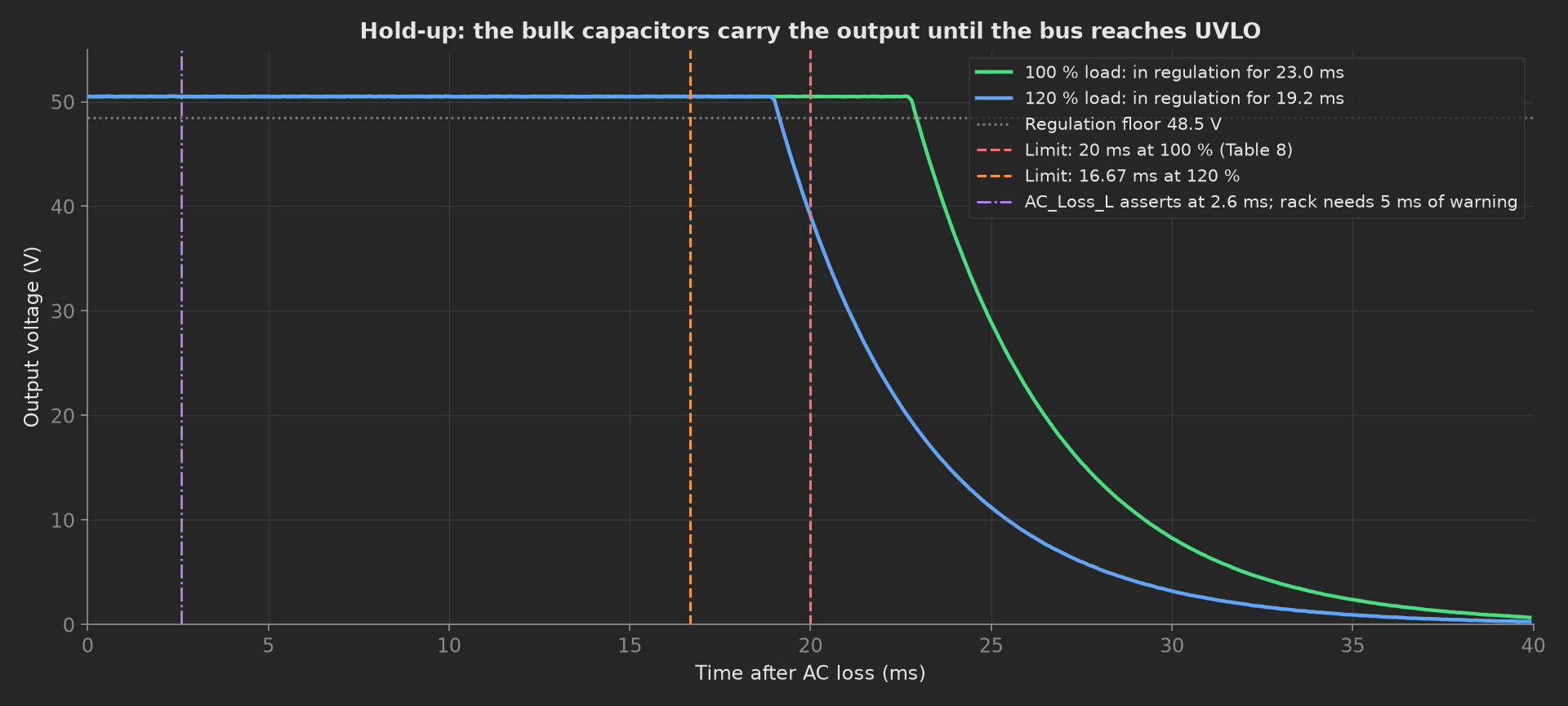
Hold-up is an energy budget: 7.2 mF between 400 V and 290 V holds 12 kW for 23 ms. A bulk capacitor at the low end of its tolerance, or one from the wrong reel, moves the knee left and fails the 120 % row first. The signal margin, 16.6 ms on the mock against the 5 ms the rack needs, is what lets the shelf's other modules pick up the load before the busbar sags.
Protections
Three trips, each cleared before the next. OVP is found by raising the module's own set-point in 0.1 V steps over the management bus until the output latches off, with the response timed on the scope; OCP by ramping the load in 2 A steps until the output leaves regulation, then timing the restart from the fault log; OTW and OTP by overriding the thermistor reading in 0.2 °C steps. After the last clear, the output must be back in regulation.
phases/protections.py52 lines
from utils.recipe import OCP_RAMP_STEP_A, OTP_SWEEP_C, OVP_TRIM_STEP_V, RATED_A, REGULATION_LOW_V, VOUT_SET_Vdef protections(measurements, bench, log): """OVP by raising the set-point over the management bus in test mode, OCP by ramping the load into constant current and timing the restart, OTW and OTP by overriding the thermistor reading. Each trip is cleared and the output checked back in regulation before the next.""" bench.set_load_a(0.5 * RATED_A) v = VOUT_SET_V while not bench.modbus_faults()["ovp"]: v = round(v + OVP_TRIM_STEP_V, 2) bench.modbus_trim_vout(v) ovp_ms = bench.ovp_response_ms() bench.modbus_clear_faults() log.info(f"OVP at {v:.2f} V, output off in {ovp_ms:.0f} ms") amps = RATED_A while not bench.modbus_faults()["ocp"]: amps += OCP_RAMP_STEP_A bench.set_load_a(amps) cc_pct = 100.0 * amps / RATED_A ocp_s = bench.ocp_shutdown_s() bench.set_load_a(0.5 * RATED_A) bench.modbus_clear_faults() log.info(f"Constant current from {amps:.0f} A ({cc_pct:.0f} %), restart after {ocp_s:.1f} s out of regulation") otw_c = None otp_c = None temp = OTP_SWEEP_C[0] while temp <= OTP_SWEEP_C[1]: bench.modbus_override_temp_c(temp) faults = bench.modbus_faults() if faults["otw"] and otw_c is None: otw_c = temp if faults["otp"]: otp_c = temp break temp = round(temp + OTP_SWEEP_C[2], 1) bench.modbus_clear_faults() recovered = bench.vout_v() > REGULATION_LOW_V log.info(f"OTW at {otw_c:.1f} C, OTP at {otp_c:.1f} C, output back at {bench.vout_v():.2f} V") measurements.ovp_trip_v = v measurements.ovp_response_ms = ovp_ms measurements.cc_limit_a = round(amps, 1) measurements.ocp_restart_s = ocp_s measurements.otw_trip_c = otw_c measurements.otp_trip_c = otp_c measurements.otp_minus_otw_c = round(otp_c - otw_c, 1) measurements.recovered_after_trips = recoveredThe 4 °C rule between OTW and OTP is the one to keep: a module whose warning and shutdown thresholds are the same value never warns, and the rack learns about the fan failure by losing 12 kW.
Blackbox and Park
The teardown phase reads the blackbox and records it as one object: two AC losses, one of each trip, no fan fault. Anything else in that log happened on its own during the test and is a reason to look. Then the log is cleared, so the first entry the customer reads was written in their rack, and the load and source go off.
def blackbox_and_park(measurements, bench, log): """Teardown: the blackbox must hold exactly the events this test caused, then it is cleared so the log the customer reads starts in their rack. Load to zero and AC off last, whatever happened before.""" bench.set_load_a(0.0) before = bench.modbus_blackbox() bench.modbus_clear_blackbox() after = bench.modbus_blackbox() bench.ac_off() measurements.blackbox_after_test = before measurements.blackbox_after_clear = after log.info(f"Blackbox held {before}, cleared to {after}, AC off")Mock Plug
PsuBench stands in for six instruments and the DUT because every reading depends on what the source and the load are doing at that instant, and plugs run in separate processes. Its efficiency is a table peaking at 97.8 % at half load with 0.03 % of noise, its inrush a 61.8 A peak decaying over 8 ms, its bulk capacitance 7.2 mF between a 400 V bus and a 290 V UVLO, its load-step response a 0.9 kHz loop with a 1.2 ms envelope, its comparators at 53.12 V, 120.4 % of rated, 85.4 °C and 95.2 °C, and its blackbox a counter that increments on every cleared fault and every AC loss. Every method returns plain Python types because plug calls cross a JSON boundary; a measurement read back from measurements.<key> returns a proxy, so the phases keep locals for their log lines.
On a real bench, split the class into the AC source and the load over SCPI, the analyzer and the hipot tester over their drivers, the scope for the inrush, ripple, load-step, hold-up and OVP captures, and the Modbus port through pymodbus. Time the AC_Loss_L edge and the OVP response on the scope, not on a polled register; interlock the hipot tester against the source; and add the 150 % hold-up row when the station gets a load that can sink it. The phases, measurements and limits stay the same.