
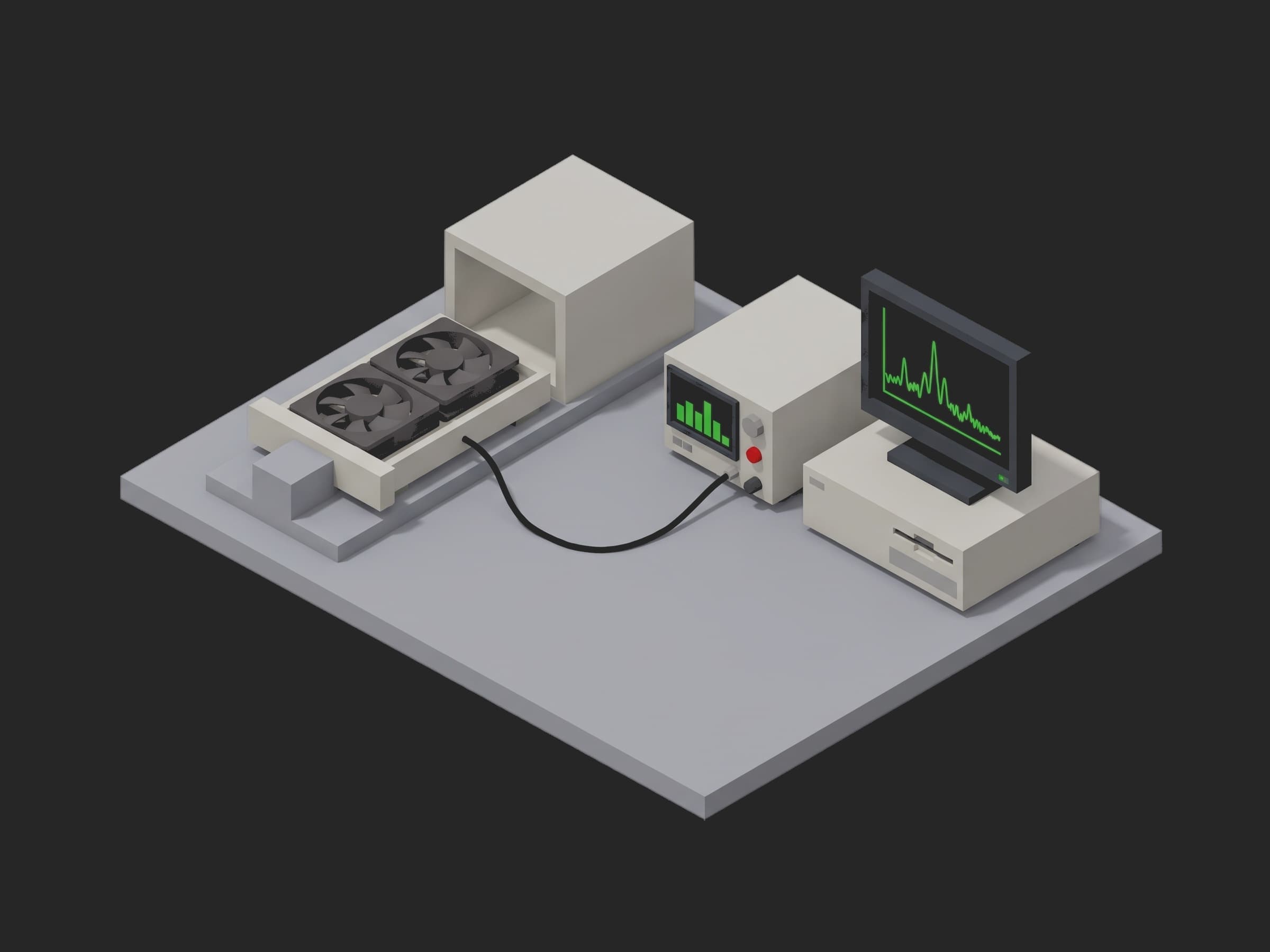
Get the complete source, dependencies and setup instructions from the template repository.
Open the source on GitHubIntroduction
Server Fan Tray Overview
A 2U server moves its heat with a row of hot-swap fan trays behind the front drive bays, each tray a sled with one or two 80 mm fans, a latch, and a blind-mate connector that carries 12 V, the PWM command and the tach return to the fan board. The dual-rotor version stacks two counter-rotating 80 mm rotors in one sled: the second rotor straightens the swirl of the first and roughly doubles the static pressure, which is what pushes air through a chassis packed with drives, DIMMs and a heat sink wall. The BMC drives every tray on one 25 kHz PWM and reads every tach, and it decides from those tachs whether a fan has failed and whether the chassis must go to full speed. One tray that ships out of spec is not one noisy fan: it is a chassis that throttles its CPUs because a rotor lags, a rack that runs its fans at 100 % because a tach reports half speed, or a node that loses a fan slot to a bearing at month six.
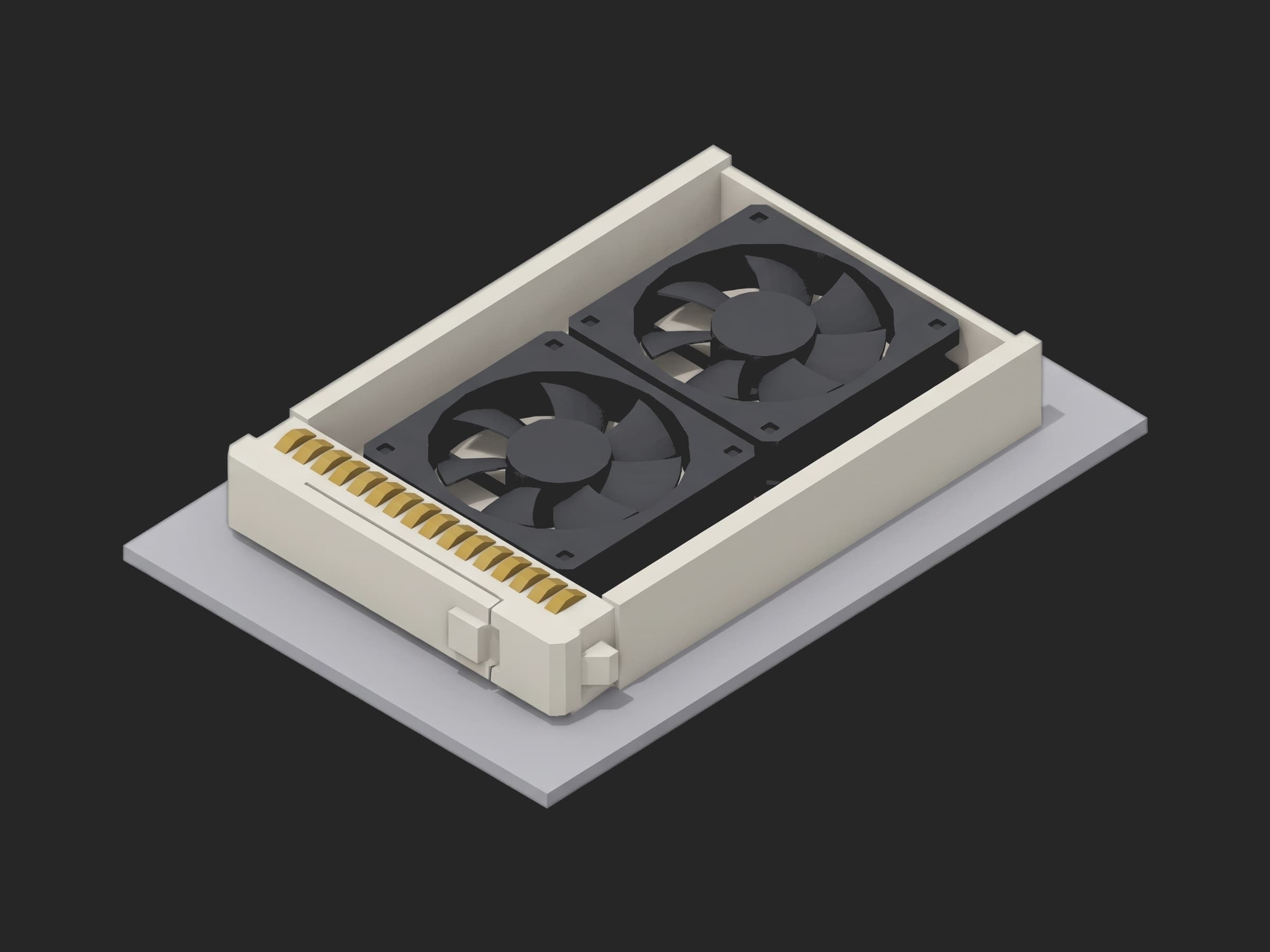
The parts this test exercises: the sled and its insulation from the fan leads, the FRU EEPROM behind the hot-swap contacts, the PWM buffer that feeds each rotor, the two motor drives and their tach outputs, the two ball-bearing pairs, the blades, and the latch that tells the operator which airflow variant is in hand.
The Intel 4-Wire Pulse Width Modulation (PWM) Controlled Fans specification, revision 1.2, is the document every server fan datasheet is written against. It sets the PWM frequency at 25 kHz, acceptable from 21 to 28 kHz (section 2.4), requires the speed, as a percentage of the fan's maximum, to match the PWM duty within 10 points at every point (3.3), caps the vendor's minimum speed at 30 % of maximum (3.2), defines the tach as two pulses per revolution on an open-collector output (2.3), caps the start-up current at 2.0 A at 13.2 V for the fans of its era (2.2), and asks for 7 500 on/off cycles of endurance (5.1.4). A fan tray vendor's end-of-line sheet adds what the fan spec leaves to the datasheet: RPM at 20, 50 and 100 % duty within 10 %, input current, airflow in CFM and static pressure on an AMCA 210 / ISO 5801 chamber, sound pressure at 1 m by ISO 7779 (ECMA-74), insulation resistance of 10 MΩ at 500 Vdc and a dielectric test at 500 Vac for one minute at 5 mA. Every limit in this template is one of those numbers, or says where it came from instead.
Test Purpose
The procedure records one end-of-line fingerprint per tray:
- Insulation resistance and dielectric leakage from the fan leads to the sled with the supply off, before anything spins
- The FRU EEPROM read through the hot-swap connector as one object against the release, its serial compared with the label, and the operator's answers on the latch colour and the finger guard
- Both rotors through 20, 30, 50, 70 and 100 % duty, speed and current on four curves, each rotor's speed in percent of its own full speed judged against the duty line, the 20 % point against the minimum-speed rule, the full speeds against the datasheet, and the two rotors against each other
- A cold start at 13.2 V, the tray current and both tachs recorded whole, judged on the peak and on the time each rotor takes to reach 90 % of the full speed the previous phase recorded
- Tach pulses per revolution against the fixture's optical tach, the tach duty, and the PWM frequency at the rotor pins behind the tray's buffer
- Airflow and static pressure across seven damper points on the chamber, judged in free air, at shut-off and at the chassis design point
- The sled's vibration spectrum at full speed, judged on the 1x tone of each rotor and the ball-pass tones of each bearing, and the sound pressure at 1 m
- A teardown that parks the PWM and the supply, puts the power cycles on the unit and the fixture's mating count on the run, and attaches the raw accelerometer capture
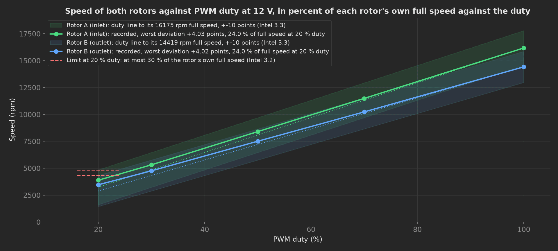
The mock tray's two rotors against the duty line: a minimum-speed clamp lifts both 4 points above it at 20 % duty, well inside the 10 point band, and both sit at 24 % of their own full speed there where the spec allows 30. The inlet rotor runs 1.2 % above its datasheet full speed and the outlet rotor 0.6 % below, which the two scalar full-speed measurements and the mismatch catch, not the curve.
The framework mechanics on show are an operator radio and a switch bound to validated measurements in a setup: phase, pre-baked from a JSON file for headless runs; a previous phase's result injected into the start-up phase as a parameter; a station-scoped plug for the chamber that keeps its damper homed and its mating counter running from one tray to the next; four multi-dimensional measurements with a different aggregation set on each axis; and a teardown: that writes unit.metadata, run.metadata and an attach.data file from a capture the bench plug kept.
Equipment & Setup
To run this end-of-line test on a production line, the following are required:
- A programmable 12 V supply rated for the tray's start-up current at 13.2 V, with a current digitizer fast enough to catch a 100 ms peak
- A DAQ with counters: two PWM outputs at 25 kHz, two tach inputs, one optical tach input, and an IEPE analog input for the accelerometer
- An AMCA 210 / ISO 5801 airflow chamber whose inlet plate carries the tray fixture, with a motorised damper, nozzle differential pressure and chamber static pressure
- An accelerometer on the sled and a class 1 sound level meter at 1 m on the inlet axis, in a hemi-anechoic booth
- An electrical safety analyzer for insulation resistance at 500 Vdc and the dielectric test at 500 Vac, interlocked so the supply cannot enable while it is connected
- An I2C adapter on the hot-swap connector's SMBus pins for the FRU EEPROM
- The Device Under Test (DUT): a dual-rotor 80 mm 12 V hot-swap fan tray with its production FRU programmed
- A TofuPilot Framework procedure to sequence the stimuli and validate the limits
- The TofuPilot Dashboard to keep the per-tray evidence and trend the bearing tones across the lot
Hardware Components
Supply, Counters and Chamber
Two rotors at 4.0 and 3.7 A running current draw about 9.7 A at 13.2 V and peak above 12 A on a cold start, so the supply is a Keysight N6700C mainframe with an N6754A module (60 V, 20 A), whose digitizer records the current waveform the start-up phase judges. An NI USB-6363 gives the two PWM counter outputs, the two tach inputs and the optical tach input, and its analog input takes the accelerometer through an IEPE conditioner (a PCB Piezotronics 352C33 on a 482C05). The airflow chamber is a Long Win LW-9266-class multi-nozzle chamber, or an Airflow Measurement Systems bench: the tray fixture is the chamber's inlet plate, the damper on the outlet sets the operating point, and the nozzle bank's differential pressure gives the flow. The optical tach is a Monarch Instrument remote optical sensor on a reflective mark on each hub.
A single-fixture station: the tray seated on the chamber's inlet plate with the blind-mate connector engaged, the supply and the DAQ beside it, the accelerometer under the sled, the microphone at 1 m on the inlet axis.
Safety Analyzer and FRU
The Chroma 19032 does the 500 Vdc insulation resistance and the 500 Vac dielectric test in one connection, with the fan leads tied together against the sled. The dielectric test is AC because the fan spec's vendors write it that way, at 500 V for one minute; a healthy tray leaks a fraction of a milliamp through the winding's capacitance to the frame, and a lead pinched under the sled leaks the full 5 mA and trips. The FRU EEPROM sits on the tray's small board with the PWM buffers and is read over the connector's SMBus pins in the IPMI FRU format; the part number, hardware revision and airflow variant in it are compared as one object with the release, and the serial with the label on the latch.
Where the Limits Come From
| Test | Limit | Basis |
|---|---|---|
| Insulation resistance | ≥ 10 MΩ at 500 Vdc | vendor EOL item |
| Dielectric | ≤ 5 mA at 500 Vac, 60 s | vendor EOL item |
| PWM frequency at the rotor pins | 21 to 28 kHz | Intel 2.4 |
| Speed against the duty | in percent of the rotor's own full speed, within 10 points of the duty at every point | Intel 3.3 |
| Speed at 20 % duty | ≤ 30 % of the rotor's own full speed | Intel 3.2 |
| Full speed | 16 000 rpm rotor A, 14 500 rpm rotor B, within 10 % | datasheet, the vendor's EOL tolerance; Intel 3.1 leaves the maximum to the vendor |
| Rotor mismatch at 100 % | ≤ 5 % between the two normalised speeds | this line's derivation: a rotor that lags its twin is loaded |
| Current at 100 % | ≤ 4.4 A rotor A, ≤ 4.1 A rotor B | datasheet maximum, rated plus 10 % |
| Start-up peak at 13.2 V | ≤ 15.4 A for the tray | Intel 2.2 caps a single fan of its era at 2.0 A; this line applies the same ratio, two rated currents, to a 7.7 A tray |
| Spin-up | both rotors at 90 % of full speed within 3 s | this line's derivation: the BMC's fan-fault window; Intel 3.2 allows a 2 s start pulse |
| Tach | exactly 2 pulses per revolution, duty 40 to 60 % | Intel 2.3 for the count; the duty window is this line's |
| Airflow in free air | ≥ 157.5 CFM | datasheet 175 CFM less 10 %, the speed tolerance applied to flow, this line's |
| Static pressure at shut-off | ≥ 810 Pa | datasheet 900 Pa less 10 % |
| Pressure at the chassis design flow | ≥ 450 Pa at 100 CFM | this line's derivation from the chassis impedance |
| 1x vibration per rotor | ≤ 1.0 g | ISO 21940-11 grade G6.3 at 16 000 rpm is 6.3 mm/s, 1.06 g at 267 Hz; this line's derivation |
| Ball-pass tones per bearing | ≤ 0.15 g | this line's derivation |
| Sound pressure at 1 m | ≤ 74 dBA | ISO 7779 / ECMA-74 method; datasheet 71 dBA plus 3 dB, this line's |
| Power cycles applied | ≤ 3 | Intel 5.1.4 budgets 7 500; the count goes on the unit |
| FRU identity, serial, latch, guard | exact match | no tolerance applies |
Three rows in that table are traps. Intel's 2.0 A start-up cap cannot be applied as written to a rotor rated at 4 A: a tray that met it would have to soft-start so slowly that it failed the spin-up window, so the limit is scaled to the ratio the spec implies and the description says so. The same section allows the spike to exceed 1.0 A for no more than 1 s, which has no clean scaling to a tray that runs at 9.7 A at 13.2 V; this line replaces it with the spin-up time. And the bearing-band limit is not a standard: it is set from what new bearings show on this fixture, and its value is a trend to watch across the lot, not a number to argue with a supplier.
Test Procedure
Overview
The procedure maps the end-of-line test onto the framework's three stages. Insulation, the FRU read and the operator's answers live in setup: so no rotor turns on a tray with a pinched lead or the wrong airflow variant. The park and the counters live in teardown: so the PWM goes to zero and the supply off even when a main phase fails.
- Setup: insulation resistance and dielectric with the supply off, FRU EEPROM, latch colour and finger guard from the operator.
- Main: both rotors through five duty points, curves, minimum speed, rotor mismatch.
- Main: cold start at 13.2 V, current and tachs whole, peak and spin-up time.
- Main: tach pulses per revolution against the optical tach, tach duty, PWM frequency.
- Main: airflow and static pressure across seven damper points on the chamber.
- Main: vibration spectrum at full speed, 1x and ball-pass tones, sound pressure at 1 m.
- Teardown: PWM to zero, supply off, cycles on the unit, mating count on the run, raw capture attached.
Every metric validates against limits declared in procedure.yaml, and results stream to TofuPilot as the per-tray evidence.
Why TofuPilot Framework?
TofuPilot Framework is a YAML + Python test framework built for hardware manufacturing. Instead of writing all your test logic, measurements, and limits inside Python code, you describe what the test does in a procedure.yaml file, and how in small Python phase files. The framework handles:
- Automatic Python environment management (via
uv) - Operator UI (no frontend code needed)
- Measurement validation and live charts
- Process isolation between phases and equipment plugs
Project Structure
You can find the full source on GitHub. The FanBench plug is a mock of the supply, the counters, the optical tach, the accelerometer, the sound level meter, the safety analyzer and the FRU link together, and FlowBench a mock of the chamber; between them they synthesize a healthy tray on the duty line with new bearings, so the procedure runs end-to-end without a bench or a tray connected. The 60 s dielectric dwell, the settling at each duty point and the spin-up return without waiting.
tofupilot run .For CI or bench automation, the same run executes headless, with the operator's two answers pre-baked from ui.json:
tofupilot run . --no-tui --no-kiosk --json --ui-values ui.jsonThe Procedure File
procedure.yaml declares the unit, the two plugs (the chamber at scope: station), and the three stages with every measurement and limit:
procedure.yaml329 lines
name: Server Fan Tray End-of-Line Testversion: 0.1.0description: End-of-line test of a dual-rotor 80 mm 12 V hot-swap fan tray for a 2U server. Insulation and dielectric with the supply off, the FRU EEPROM read through the hot-swap connector against the release, both rotors through the PWM duty points with the speed in percent of full speed against the duty line, a cold start at 13.2 V with the current recorded whole, tach pulses per revolution against the fixture's optical tach, airflow and static pressure on the chamber, the vibration spectrum for imbalance and bearing tones, sound pressure at 1 m, and a teardown that parks the tray, counts its power cycles and attaches the raw accelerometer capture.unit: auto_identify: true serial_number: description: "Scan the label on the tray's latch" placeholder: "FT80-0000000" pattern: "^FT80-\\d{7}$" default_value: "FT80-0031842" part_number: default_value: "FT-2U-80CR-12" batch_number: default_value: "LOT-2026-38"plugs: - name: Fan Bench description: "12 V supply with current digitizer, PWM and tach counters, optical tach, accelerometer, sound level meter, safety analyzer and the I2C link to the FRU EEPROM (mock, one plug per bench)" python: plugs.fan_bench:FanBench key: bench config: serial_number: "FT80-0031842" - name: Flow Chamber description: "AMCA 210 / ISO 5801 nozzle chamber whose inlet plate is the tray fixture, damper, pressures and the connector mating counter (mock, held across trays)" python: plugs.flow_bench:FlowBench key: flow_bench scope: stationsetup: - name: Identify and Insulation key: identify_and_insulation python: phases.identify_and_insulation ui: components: - key: latch type: radio label: "Latch colour" description: "The latch colour is the airflow variant; this line builds front-to-back trays" required: true bind: measurements.latch_airflow options: - label: "Blue latch, front-to-back" value: "front-to-back" - label: "Red latch, back-to-front" value: "back-to-front" - key: grille type: switch label: "Finger guard seated on the outlet rotor" description: "The chamber reads the tray with its guard, as it ships" required: true bind: measurements.grille_seated measurements: - name: Latch Airflow Variant key: latch_airflow description: "Operator's answer. A back-to-front tray passes every electrical test and starves the chassis." validators: - {operator: "==", expected_value: "front-to-back"} - name: Finger Guard Seated key: grille_seated validators: - {operator: "==", expected_value: true} - name: Insulation Resistance key: insulation_mohm unit: MΩ description: "All lines tied together against the sled at 500 Vdc (vendor EOL item)." validators: - {operator: ">=", expected_value: 10.0} - name: Dielectric Leakage key: dielectric_leakage_ma unit: mA description: "500 Vac lines to sled for 60 s (vendor EOL item); the mock returns without the dwell." validators: - {operator: "<=", expected_value: 5.0} - name: FRU Identity key: fru_identity description: Part number, hardware revision, airflow variant and FRU format from the EEPROM as one object against the release. validators: - operator: "==" expected_value: part_number: FT-2U-80CR-12 hw_rev: B2 airflow: front-to-back fru_format: ipmi-1.0 - name: EEPROM Serial Matches Label key: eeprom_serial_matches_label description: The serial the BMC will inventory is the one on the latch. validators: - {operator: "==", expected_value: true}main: - name: PWM to RPM Curve key: pwm_rpm_curve python: phases.pwm_rpm_curve measurements: - name: PWM Curve key: pwm_curve title: Speed and current of both rotors against PWM duty at 12 V, speed judged in percent of full speed against the duty x_axis: legend: PWM duty unit: "%" y_axis: - legend: Rotor A speed key: rpm_a unit: rpm aggregations: - type: max_dev_pct unit: "%" validators: - {operator: "<=", expected_value: 10.0} - type: min_speed_pct unit: "%" validators: - {operator: "<=", expected_value: 30.0} - legend: Rotor B speed key: rpm_b unit: rpm aggregations: - type: max_dev_pct unit: "%" validators: - {operator: "<=", expected_value: 10.0} - type: min_speed_pct unit: "%" validators: - {operator: "<=", expected_value: 30.0} - legend: Rotor A current key: current_a unit: A aggregations: - type: at_100_pct_a unit: A validators: - {operator: "<=", expected_value: 4.4} - legend: Rotor B current key: current_b unit: A aggregations: - type: at_100_pct_a unit: A validators: - {operator: "<=", expected_value: 4.1} - name: Full Speed A key: full_speed_a_rpm unit: rpm description: "16 000 rpm at 100 % duty on the datasheet, within the datasheet's 10 % (Intel 3.1 leaves the maximum to the vendor); the reference for the spin-up time." validators: - {operator: ">=", expected_value: 14400.0} - {operator: "<=", expected_value: 17600.0} - name: Full Speed B key: full_speed_b_rpm unit: rpm description: "14 500 rpm at 100 % duty on the datasheet, within 10 %." validators: - {operator: ">=", expected_value: 13050.0} - {operator: "<=", expected_value: 15950.0} - name: Rotor Mismatch key: rotor_mismatch_pct unit: "%" description: "Each rotor's full speed as a fraction of its own nominal; the two fractions must agree within 5 %. This line's derivation: a rotor that lags its twin is loaded by a rubbing blade or a bearing, even while still inside its own 10 %." validators: - {operator: "<=", expected_value: 5.0} - name: Start-Up Current key: startup_current python: phases.startup_current depends_on: [pwm_rpm_curve] measurements: - name: Start-Up key: startup title: Tray current and both rotor speeds on a 0 to 100 percent step at 13.2 V (Intel 2.2) x_axis: legend: Time after the step unit: s y_axis: - legend: Tray current key: current unit: A aggregations: - type: peak_a unit: A validators: - {operator: "<=", expected_value: 15.4} - legend: Rotor A speed key: rpm_a unit: rpm aggregations: - type: t90_s unit: s validators: - {operator: "<=", expected_value: 3.0} - legend: Rotor B speed key: rpm_b unit: rpm aggregations: - type: t90_s unit: s validators: - {operator: "<=", expected_value: 3.0} - name: Tach Integrity key: tach_integrity python: phases.tach_integrity depends_on: [startup_current] measurements: - name: Tach Pulses Per Revolution A key: tach_pulses_per_rev_a description: "Tach frequency over the optical tach's speed (Intel 2.3: two pulses per revolution)." validators: - {operator: "==", expected_value: 2} - name: Tach Duty A key: tach_duty_a_pct unit: "%" validators: - {operator: ">=", expected_value: 40.0} - {operator: "<=", expected_value: 60.0} - name: PWM Frequency at Rotor A key: pwm_freq_a_khz unit: kHz description: "At the rotor pins behind the tray's buffer (Intel 2.4: 25 kHz target, 21 to 28 accepted)." validators: - {operator: ">=", expected_value: 21.0} - {operator: "<=", expected_value: 28.0} - name: Tach Pulses Per Revolution B key: tach_pulses_per_rev_b validators: - {operator: "==", expected_value: 2} - name: Tach Duty B key: tach_duty_b_pct unit: "%" validators: - {operator: ">=", expected_value: 40.0} - {operator: "<=", expected_value: 60.0} - name: PWM Frequency at Rotor B key: pwm_freq_b_khz unit: kHz validators: - {operator: ">=", expected_value: 21.0} - {operator: "<=", expected_value: 28.0} - name: Airflow and Static Pressure key: airflow_and_pressure python: phases.airflow_and_pressure depends_on: [tach_integrity] timeout: 5m measurements: - name: Fan Curve key: fan_curve title: Airflow and static pressure at 100 percent duty, damper from open to shut x_axis: legend: Damper opening unit: "%" y_axis: - legend: Airflow key: airflow unit: CFM aggregations: - type: free_air_cfm unit: CFM validators: - {operator: ">=", expected_value: 157.5} - legend: Static pressure key: static_pressure unit: Pa aggregations: - type: shutoff_pa unit: Pa validators: - {operator: ">=", expected_value: 810.0} - type: at_design_cfm_pa unit: Pa validators: - {operator: ">=", expected_value: 450.0} - name: Vibration and Acoustic key: vibration_and_acoustic python: phases.vibration_and_acoustic depends_on: [airflow_and_pressure] measurements: - name: Vibration Spectrum key: spectrum title: Sled acceleration spectrum at 100 percent duty, 20 kHz capture x_axis: legend: Frequency unit: Hz y_axis: - legend: Amplitude key: amplitude unit: g aggregations: - type: one_x_a_g unit: g validators: - {operator: "<=", expected_value: 1.0} - type: one_x_b_g unit: g validators: - {operator: "<=", expected_value: 1.0} - type: bearing_a_g unit: g validators: - {operator: "<=", expected_value: 0.15} - type: bearing_b_g unit: g validators: - {operator: "<=", expected_value: 0.15} - name: Sound Pressure at 1 m key: sound_pressure_dba unit: dBA description: "ISO 7779 / ECMA-74 method, 1 m on the inlet axis, hemi-anechoic booth. Datasheet 71 dBA plus 3 dB, this line's derivation." validators: - {operator: "<=", expected_value: 74.0}teardown: - name: Park and Cycles key: park_and_cycles python: phases.park_and_cycles measurements: - name: Current After Park key: current_after_park_a unit: A description: Supply off, nothing back-feeds the tray. validators: - {operator: "<=", expected_value: 0.01} - name: Power Cycles Applied key: power_cycles_applied description: "Two in this procedure, against the 7 500 on/off cycles of Intel 5.1.4; the count goes on the unit." validators: - {operator: "<=", expected_value: 3}Framework features to notice:
- Operator answers as validated measurements. The setup phase's
ui:carries a radio bound tomeasurements.latch_airflowand a switch bound tomeasurements.grille_seated; both validate like any other measurement (== front-to-back,== true), and the run records what the operator actually answered. Headless runs take the two answers fromui.jsonthrough--ui-values. - A previous result as a parameter.
startup_currentnamespwm_rpm_curveas a function parameter and readsfull_speed_a_rpmandfull_speed_b_rpmfrom it, so the spin-up time is measured against this tray's own full speed, not the datasheet's. scope: stationfor the chamber. TheFlowBenchinstance survives from one tray to the next: the damper stays homed and the connector mating counter keeps counting. In a one-shottofupilot runit behaves as execution scope, which is why the mock reports a mating count of one.- Four curves, four aggregation sets.
pwm_curvecarries two speed axes judged onmax_dev_pctandmin_speed_pctand two current axes judged onat_100_pct_a;startupcarries the current judged onpeak_aand both tachs judged ont90_s;fan_curveandspectrumeach judge one waveform on two to four numbers while the whole trace stays attached. - A whole object, compared once.
fru_identityvalidates with one==; the report shows which key differed.tach_pulses_per_rev_ais an integer== 2. teardown:writes the record.unit.metadata["power_cycles"],run.metadata["fixture_matings"]andattach.data(...)of the raw accelerometer capture the bench plug kept, whatever a main phase did.
Identify and Insulation
The tray is seated, the connector mated, and the safety analyzer runs with the supply off: all lines tied together against the sled at 500 Vdc for the insulation resistance, then 500 Vac for the dielectric leakage. The mock returns the dielectric reading without the 60 s dwell and the log says so. Then the first power-on at 0 % duty and the FRU EEPROM read: part number, hardware revision, airflow variant and format as one object, the serial against the label. The operator's two answers arrive through the bindings; the phase does not touch them.
phases/identify_and_insulation.py28 lines
from utils.recipe import DIELECTRIC_DWELL_S, DIELECTRIC_VAC, IR_TEST_VDC, SUPPLY_Vdef identify_and_insulation(measurements, bench, flow_bench, unit, run, log): """Setup: the tray is seated on the chamber's inlet plate, the safety analyzer tests the lines against the sled with the supply off, then the first power-on reads the FRU EEPROM through the hot-swap connector. The operator's answers on the latch colour and the grille arrive as bound measurements. A tray with a pinched lead under the sled, or the wrong airflow variant, stops here before the rotors turn.""" flow_bench.clamp() run.metadata["fixture_matings"] = flow_bench.mating_count() bench.supply_off() ir = bench.insulation_mohm(IR_TEST_VDC) leak = bench.dielectric_ma(DIELECTRIC_VAC, DIELECTRIC_DWELL_S) log.info(f"{unit.serial_number}: {ir:.0f} MOhm at {IR_TEST_VDC:.0f} Vdc, {leak:.3f} mA at {DIELECTRIC_VAC:.0f} Vac (mock: the {DIELECTRIC_DWELL_S:.0f} s dwell is not waited)") bench.supply_on(SUPPLY_V) bench.set_duty("a", 0.0) bench.set_duty("b", 0.0) fru = bench.fru_identity() serial = bench.fru_serial() measurements.insulation_mohm = ir measurements.dielectric_leakage_ma = leak measurements.fru_identity = fru measurements.eeprom_serial_matches_label = serial == unit.serial_number unit.metadata["hw_rev"] = fru["hw_rev"] log.info(f"FRU {fru['part_number']} rev {fru['hw_rev']} {fru['airflow']}, EEPROM serial {serial}, label {unit.serial_number}")PWM to RPM Curve
Both rotors are stepped through 20, 30, 50, 70 and 100 % duty at 12 V; at each point the tach gives the speed and the fixture's shunt the current on that rotor's feed. The spec's curve is the duty line: the speed as a percentage of the rotor's own full speed must match the duty within 10 points, and the 20 % point must sit at or below 30 %. The full speed itself is judged against the datasheet as a scalar, and the two full speeds against each other once normalised. A rotor still inside its own 10 % but 5 % behind its twin is dragging a blade or a bearing.
phases/pwm_rpm_curve.py57 lines
import numpy as npfrom utils.recipe import DUTY_POINTS_PCT, NOMINAL_MAX_RPM, ROTORS, SETTLE_S, SUPPLY_Vdef curve_stats(rotor, rpm, log): """Intel 3.3: the speed as a percentage of the rotor's own full speed must match the duty within 10 points; 3.2: the 20 % point at or below 30 % of full speed.""" pct_of_full = 100.0 * np.array(rpm) / rpm[-1] dev = pct_of_full - np.array(DUTY_POINTS_PCT) worst = dev[np.argmax(np.abs(dev))] log.info(f"Rotor {rotor.upper()}: worst deviation {worst:+.2f} points from the duty line, {pct_of_full[0]:.1f} % of full speed at {DUTY_POINTS_PCT[0]} % duty") return round(float(abs(worst)), 2), round(float(pct_of_full[0]), 1)def pwm_rpm_curve(measurements, bench, log): """Both rotors through the duty points at 12 V, speed from each tach and current from each feed. Each rotor is judged against the duty line (speed in percent of its own full speed within 10 points of the duty, the 20 % point at or below 30 %), its full speed against the datasheet, and the two rotors against each other at 100 %: a rotor that lags its twin is loaded, even inside its own band.""" bench.supply_on(SUPPLY_V) rpm = {r: [] for r in ROTORS} amps = {r: [] for r in ROTORS} for duty in DUTY_POINTS_PCT: for r in ROTORS: bench.set_duty(r, duty) bench.settle(SETTLE_S) for r in ROTORS: rpm[r].append(bench.tach_rpm(r)) amps[r].append(bench.rotor_current_a(r)) log.info(f"{duty:3d} %: A {rpm['a'][-1]:.0f} rpm {amps['a'][-1]:.2f} A, B {rpm['b'][-1]:.0f} rpm {amps['b'][-1]:.2f} A") dev_a, min_a = curve_stats("a", rpm["a"], log) dev_b, min_b = curve_stats("b", rpm["b"], log) m = measurements.pwm_curve m.x_axis = DUTY_POINTS_PCT m.y_axis.rpm_a = rpm["a"] m.y_axis.rpm_a.aggregations.max_dev_pct = dev_a m.y_axis.rpm_a.aggregations.min_speed_pct = min_a m.y_axis.rpm_b = rpm["b"] m.y_axis.rpm_b.aggregations.max_dev_pct = dev_b m.y_axis.rpm_b.aggregations.min_speed_pct = min_b m.y_axis.current_a = amps["a"] m.y_axis.current_a.aggregations.at_100_pct_a = amps["a"][-1] m.y_axis.current_b = amps["b"] m.y_axis.current_b.aggregations.at_100_pct_a = amps["b"][-1] full_a = rpm["a"][-1] full_b = rpm["b"][-1] mismatch = 100.0 * abs(full_a / NOMINAL_MAX_RPM["a"] - full_b / NOMINAL_MAX_RPM["b"]) measurements.full_speed_a_rpm = full_a measurements.full_speed_b_rpm = full_b measurements.rotor_mismatch_pct = round(mismatch, 2) log.info(f"Full speed A {full_a:.0f} rpm, B {full_b:.0f} rpm, normalised mismatch {mismatch:.2f} %")Start-Up Current
Supply off, both duties at zero, then the supply at 13.2 V and both duties stepped to 100 % at once. The tray current and both tachs are recorded together from the supply's digitizer and the counters; the phase judges the peak against the scaled Intel limit, and the time each rotor takes to reach 90 % of the full speed the previous phase recorded, injected as the pwm_rpm_curve parameter.
phases/startup_current.py36 lines
import numpy as npfrom utils.recipe import STARTUP_V, SUPPLY_Vdef time_to_pct(t_s, rpm, target_rpm): """First sample at or above the target speed.""" idx = np.where(np.asarray(rpm) >= target_rpm)[0] return float(t_s[idx[0]]) if len(idx) else float(t_s[-1])def startup_current(measurements, bench, pwm_rpm_curve, log): """Cold start at 13.2 V, the supply's upper tolerance, both duties stepped from 0 to 100 % at once: the tray current recorded whole from the supply's digitizer, both tachs alongside. The peak is judged against the scaled Intel limit and each rotor against the time it takes to reach 90 % of the full speed the previous phase recorded.""" bench.set_duty("a", 0.0) bench.set_duty("b", 0.0) bench.supply_off() t_s, amps, rpm_a, rpm_b = bench.startup_capture(STARTUP_V) bench.supply_on(SUPPLY_V) t = np.asarray(t_s) peak = float(np.max(amps)) t90_a = time_to_pct(t, rpm_a, 0.9 * float(pwm_rpm_curve.full_speed_a_rpm)) t90_b = time_to_pct(t, rpm_b, 0.9 * float(pwm_rpm_curve.full_speed_b_rpm)) m = measurements.startup m.x_axis = t_s m.y_axis.current = amps m.y_axis.current.aggregations.peak_a = round(peak, 2) m.y_axis.rpm_a = rpm_a m.y_axis.rpm_a.aggregations.t90_s = round(t90_a, 3) m.y_axis.rpm_b = rpm_b m.y_axis.rpm_b.aggregations.t90_s = round(t90_b, 3) log.info(f"Start at {STARTUP_V} V: peak {peak:.2f} A at {t[int(np.argmax(amps))]:.3f} s, A at 90 % in {t90_a:.2f} s, B in {t90_b:.2f} s over {len(amps)} samples (mock: capture returned without waiting)")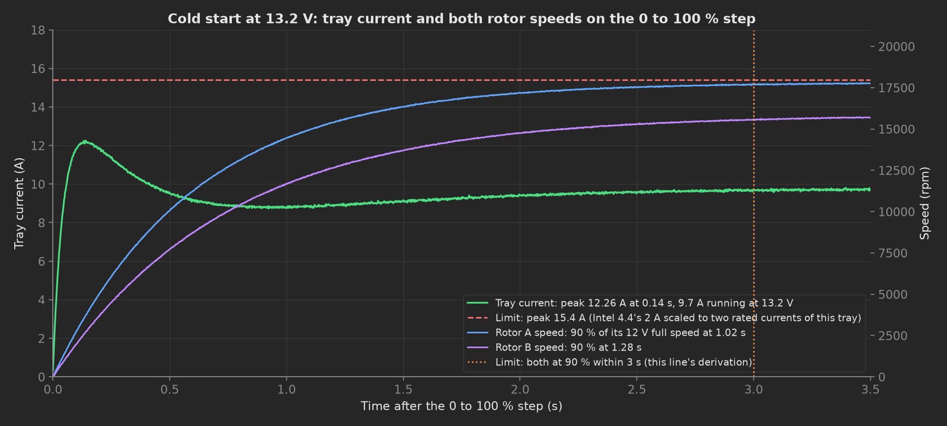
The mock tray's cold start: each drive holds its winding at twice rated current until the rotor's back-EMF builds, so the tray peaks at 12.3 A at 140 ms and settles to 9.7 A at 13.2 V, the current the spec's 1 s spike clause was written around for a fan a tenth this size. A rotor with a seized bearing holds its start-up current and never reaches 90 %; a drive with its current limit mis-set peaks above the line.
Tach Integrity
At 50 % duty, each rotor's tach frequency is counted for one second next to the optical tach on its hub; the ratio is the pulses per revolution and must be exactly two. The tach duty is read from the counter and the PWM frequency at the rotor's pins, behind the tray's buffer, on the same DAQ. A tray whose buffer regenerates the PWM at the wrong frequency runs its rotors outside the curve the BMC expects.
phases/tach_integrity.py29 lines
from utils.recipe import ROTORS, SETTLE_S, SUPPLY_V, TACH_CHECK_DUTY_PCTdef tach_integrity(measurements, bench, log): """At 50 % duty, each rotor's tach frequency against the fixture's optical tach on the hub: pulses per revolution must be exactly two, the tach duty inside the window, and the PWM at the rotor pins, behind the tray's buffer, inside the Intel frequency window. A BMC counting a one-pulse tach reads the rotor at half speed and drives the whole chassis to full speed for nothing.""" bench.supply_on(SUPPLY_V) for r in ROTORS: bench.set_duty(r, TACH_CHECK_DUTY_PCT) bench.settle(SETTLE_S) for r in ROTORS: tach_hz = bench.tach_frequency_hz(r) optical_rpm = bench.optical_rpm(r) pulses = tach_hz * 60.0 / optical_rpm duty = bench.tach_duty_pct(r) pwm_khz = bench.pwm_frequency_khz(r) log.info(f"Rotor {r.upper()}: tach {tach_hz:.1f} Hz, optical {optical_rpm:.0f} rpm, {pulses:.3f} pulses/rev, tach duty {duty:.1f} %, PWM {pwm_khz:.2f} kHz at the pins") if r == "a": measurements.tach_pulses_per_rev_a = int(round(pulses)) measurements.tach_duty_a_pct = duty measurements.pwm_freq_a_khz = pwm_khz else: measurements.tach_pulses_per_rev_b = int(round(pulses)) measurements.tach_duty_b_pct = duty measurements.pwm_freq_b_khz = pwm_khzAirflow and Static Pressure
Both rotors at 100 %, the damper walked from fully open to shut in seven steps, airflow from the nozzle bank and static pressure from the chamber tap at each. Free-air flow and shut-off pressure are judged against the datasheet less the tolerance; the curve is interpolated at the chassis design flow, the point the server actually needs. On a real chamber each point settles for seconds, which is what the phase's timeout is for.
phases/airflow_and_pressure.py31 lines
import numpy as npfrom utils.recipe import CHASSIS_DESIGN_CFM, DAMPER_POINTS, ROTORS, SETTLE_S, SUPPLY_Vdef airflow_and_pressure(measurements, bench, flow_bench, log): """Both rotors at 100 % on the chamber, the damper walked from fully open to shut: airflow from the nozzle bank and static pressure from the chamber tap at each point. Free-air flow and shut-off pressure are judged against the datasheet, and the curve is interpolated at the chassis design flow, the point the server needs. On a real chamber each point settles for seconds; the mock returns at once.""" bench.supply_on(SUPPLY_V) for r in ROTORS: bench.set_duty(r, 100.0) bench.settle(SETTLE_S) cfm, pa = flow_bench.fan_curve(DAMPER_POINTS) opening = np.linspace(100.0, 0.0, DAMPER_POINTS).round(1).tolist() # the curve is sampled with flow decreasing; interp wants it increasing at_design = float(np.interp(CHASSIS_DESIGN_CFM, cfm[::-1], pa[::-1])) for o, q, p in zip(opening, cfm, pa): log.info(f"Damper {o:5.1f} % open: {q:6.1f} CFM at {p:4.0f} Pa") m = measurements.fan_curve m.x_axis = opening m.y_axis.airflow = cfm m.y_axis.airflow.aggregations.free_air_cfm = cfm[0] m.y_axis.static_pressure = pa m.y_axis.static_pressure.aggregations.shutoff_pa = pa[-1] m.y_axis.static_pressure.aggregations.at_design_cfm_pa = round(at_design, 0) log.info(f"Free air {cfm[0]:.1f} CFM, shut-off {pa[-1]:.0f} Pa, {at_design:.0f} Pa at the chassis design point of {CHASSIS_DESIGN_CFM:.0f} CFM")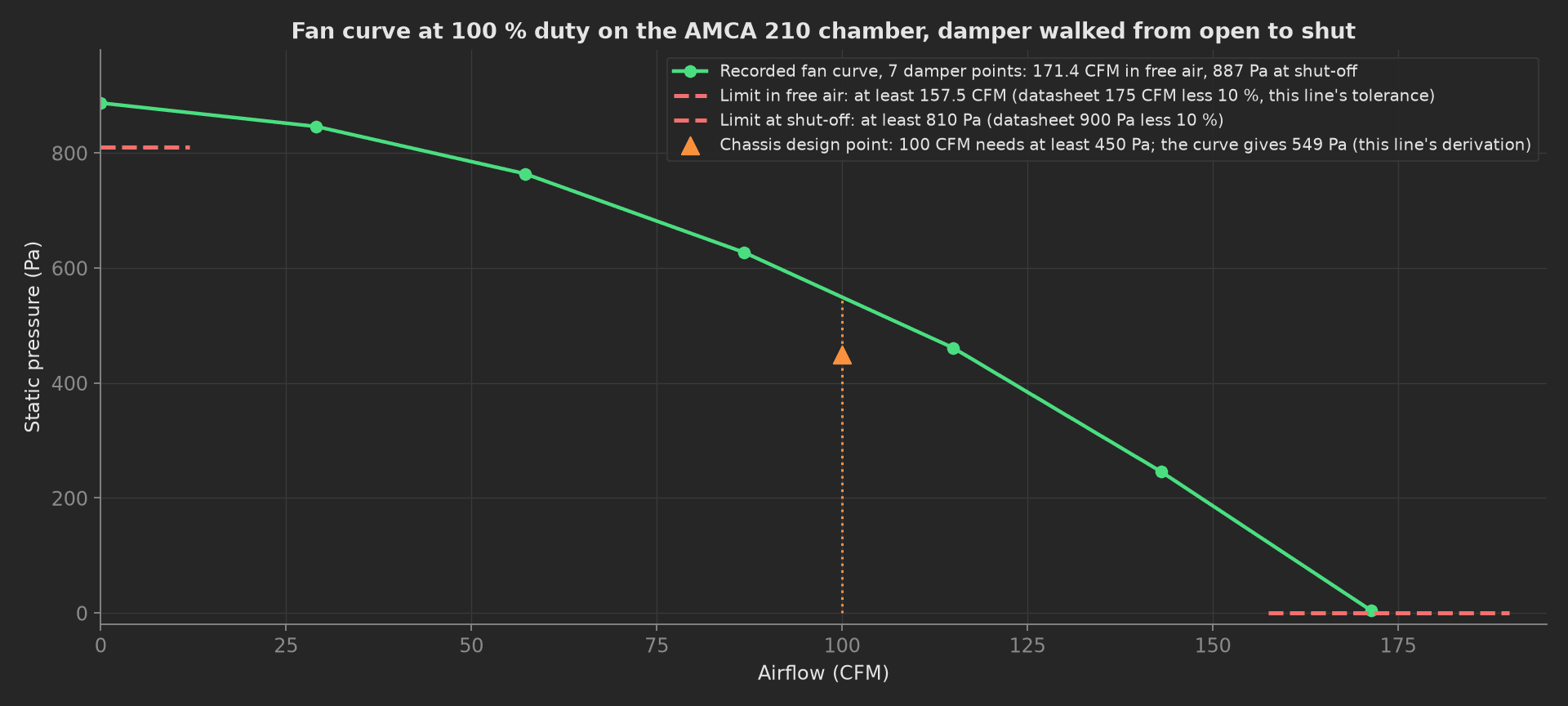
The mock tray's fan curve: 171.4 CFM in free air, 887 Pa at shut-off, 549 Pa at the 100 CFM the chassis draws. A rotor with a bent blade loses the shut-off end first; a tray with a guard that is not seated loses the free-air end.
Vibration and Acoustic
One accelerometer capture on the sled at full speed, 0.5 s at 20 kHz, the spectrum by FFT with a Hann window. The shaft frequency of each rotor comes from its tach, so the 1x tone is read where it is, not where the datasheet says; the ball-pass frequencies of the outer and inner race come from the bearing geometry in the recipe. The blade-pass tone at seven times the shaft frequency is logged and not judged: it is the aerodynamics, not a defect. Then the sound level meter at 1 m.
phases/vibration_and_acoustic.py49 lines
import numpy as npfrom utils.recipe import BLADES, ROTORS, SETTLE_S, VIB_SAMPLE_HZ, VIB_SPECTRUM_MAX_HZ, bearing_defect_frequenciesdef peak_near(freqs, spectrum, target_hz, tolerance_bins=3): """Largest bin within a few bins of the target, so a speed that drifts a few rpm during the capture still lands on the tone.""" idx = int(np.argmin(np.abs(freqs - target_hz))) lo = max(0, idx - tolerance_bins) hi = min(len(spectrum), idx + tolerance_bins + 1) return float(np.max(spectrum[lo:hi]))def vibration_and_acoustic(measurements, bench, log): """Both rotors at 100 %, one accelerometer capture on the sled, the spectrum by FFT. The 1x tone of each rotor, at the shaft frequency the tach gives, is the imbalance; the ball-pass tones of each rotor's bearing are the bearing check. The blade-pass tone is logged, not judged: it is the fan's aerodynamics, not a defect. Then the A-weighted sound pressure at 1 m on the inlet axis.""" bench.settle(SETTLE_S) samples = np.asarray(bench.vibration_capture()) window = np.hanning(len(samples)) spectrum = np.abs(np.fft.rfft(samples * window)) * 2.0 / np.sum(window) freqs = np.fft.rfftfreq(len(samples), 1.0 / VIB_SAMPLE_HZ) one_x = {} bearing = {} for r in ROTORS: f_r = bench.tach_rpm(r) / 60.0 d = bearing_defect_frequencies(f_r) one_x[r] = peak_near(freqs, spectrum, f_r) bpfo = peak_near(freqs, spectrum, d["bpfo"]) bpfi = peak_near(freqs, spectrum, d["bpfi"]) bearing[r] = max(bpfo, bpfi) blade = peak_near(freqs, spectrum, BLADES * f_r) log.info(f"Rotor {r.upper()} at {f_r * 60:.0f} rpm: 1x {one_x[r]:.3f} g at {f_r:.0f} Hz, BPFO {bpfo:.3f} g at {d['bpfo']:.0f} Hz, BPFI {bpfi:.3f} g at {d['bpfi']:.0f} Hz, blade pass {blade:.3f} g at {BLADES * f_r:.0f} Hz") spl = bench.sound_pressure_dba() keep = freqs <= VIB_SPECTRUM_MAX_HZ m = measurements.spectrum m.x_axis = freqs[keep].round(1).tolist() m.y_axis.amplitude = spectrum[keep].round(4).tolist() m.y_axis.amplitude.aggregations.one_x_a_g = round(one_x["a"], 3) m.y_axis.amplitude.aggregations.one_x_b_g = round(one_x["b"], 3) m.y_axis.amplitude.aggregations.bearing_a_g = round(bearing["a"], 3) m.y_axis.amplitude.aggregations.bearing_b_g = round(bearing["b"], 3) measurements.sound_pressure_dba = spl log.info(f"{spl:.1f} dBA at 1 m, {int(keep.sum())} bins to {VIB_SPECTRUM_MAX_HZ:.0f} Hz")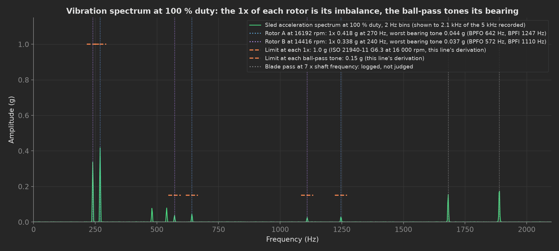
The mock tray's spectrum: two 1x tones under half the limit, ball-pass tones of new bearings at 0.04 g, the two blade-pass tones above the bearing limit and ignored by design. A dented outer race puts a tone at 2.38 times the shaft frequency that grows week by week in the field; this phase catches it at 0.15 g on the line, and the raw capture attached at teardown lets it be re-analysed later with a different band.
Park and Cycles
The teardown phase sets both duties to zero and switches the supply off, releases the tray from the chamber plate, and records what the test did to the unit: the power cycles applied, against the 7 500 of the fan spec's 5.1.4, go on the unit; the fixture's mating count goes on the run, so the connector on the fixture is replaced on a count and not on a failure; and the raw accelerometer capture the bench plug kept is attached as CSV.
phases/park_and_cycles.py32 lines
import ioimport numpy as npfrom utils.recipe import ROTORSdef park_and_cycles(measurements, bench, flow_bench, unit, run, attach, log): """Teardown: PWM to 0 on both rotors, supply off, the tray released from the chamber plate, whatever happened before. The power cycles this test applied go on the unit against its 7 500-cycle budget, the fixture's mating count on the run for connector wear, and the raw accelerometer capture is attached so a bearing can be re-analysed later without the tray.""" for r in ROTORS: bench.set_duty(r, 0.0) bench.supply_off() residual = bench.supply_current_a() flow_bench.release() cycles = bench.power_cycles() matings = flow_bench.mating_count() measurements.current_after_park_a = residual measurements.power_cycles_applied = cycles unit.metadata["power_cycles"] = cycles run.metadata["fixture_matings"] = matings raw = bench.last_vibration_capture() if raw: buf = io.StringIO() np.savetxt(buf, np.asarray(raw["samples"]), fmt="%.5f", header=f"acceleration_g at {raw['sample_rate_hz']:.0f} Hz", comments="# ") attach.data(buf.getvalue().encode(), "vibration_raw_20khz.csv") log.info(f"Parked: {residual:.4f} A with the supply off, {cycles} power cycles applied, fixture mating {matings}, raw capture {'attached' if raw else 'absent'}")Mock Plugs
FanBench stands in for six instruments and the DUT because every reading depends on the duty and the supply voltage at that instant, and plugs run in separate processes. Its rotors follow the duty line with a 4 point lift at 20 % duty, the inlet rotor 1.2 % fast and the outlet rotor 0.6 % slow on full speed, its currents follow speed to the power 2.5 from a 0.15 A idle, its cold start holds each winding at twice rated current until the back-EMF builds, its tachs are clean two-pulse square waves, its spectrum carries the 1x, 2x, blade-pass and ball-pass tones of each rotor on 0.02 g of noise, and it keeps the last capture for the teardown. FlowBench holds the chamber at scope: station: a fan curve from 172 CFM in free air to 885 Pa at shut-off, and a mating counter that increments on every clamp. Every method returns plain Python types because plug calls cross a JSON boundary; a measurement read back from measurements.<key> returns a proxy, so the phases keep locals for their log lines.
On a real bench, split FanBench into the supply over SCPI, the DAQ through nidaqmx for the PWM outputs, the tach and optical inputs and the IEPE channel, the sound level meter over its API, the safety analyzer over SCPI and the FRU EEPROM over smbus; keep FlowBench on the chamber's serial protocol and at station scope. Interlock the safety analyzer against the supply, let each damper point settle before reading, and wait the full 60 s dielectric dwell. The phases, measurements and limits stay the same.