
Get the complete source, dependencies and setup instructions from the template repository.
Open the source on GitHub ↗Introduction
Reaction Wheel Acceptance Overview
A reaction wheel is a flywheel on a pair of ball bearings, driven by a brushless motor, and it is the one mechanism on a small satellite that runs continuously for the whole mission. Every unit that leaves the vendor's line is accepted on the same set of numbers: how much the bearings drag once they have settled, how well the rotor is balanced, how much bus power it draws at speed, and how much force and torque it exports into the structure while it spins. The last one is the micro-vibration budget of the spacecraft; a wheel that shakes the optical bench at 100 Hz is a wheel the payload cannot use, whatever its momentum rating says.
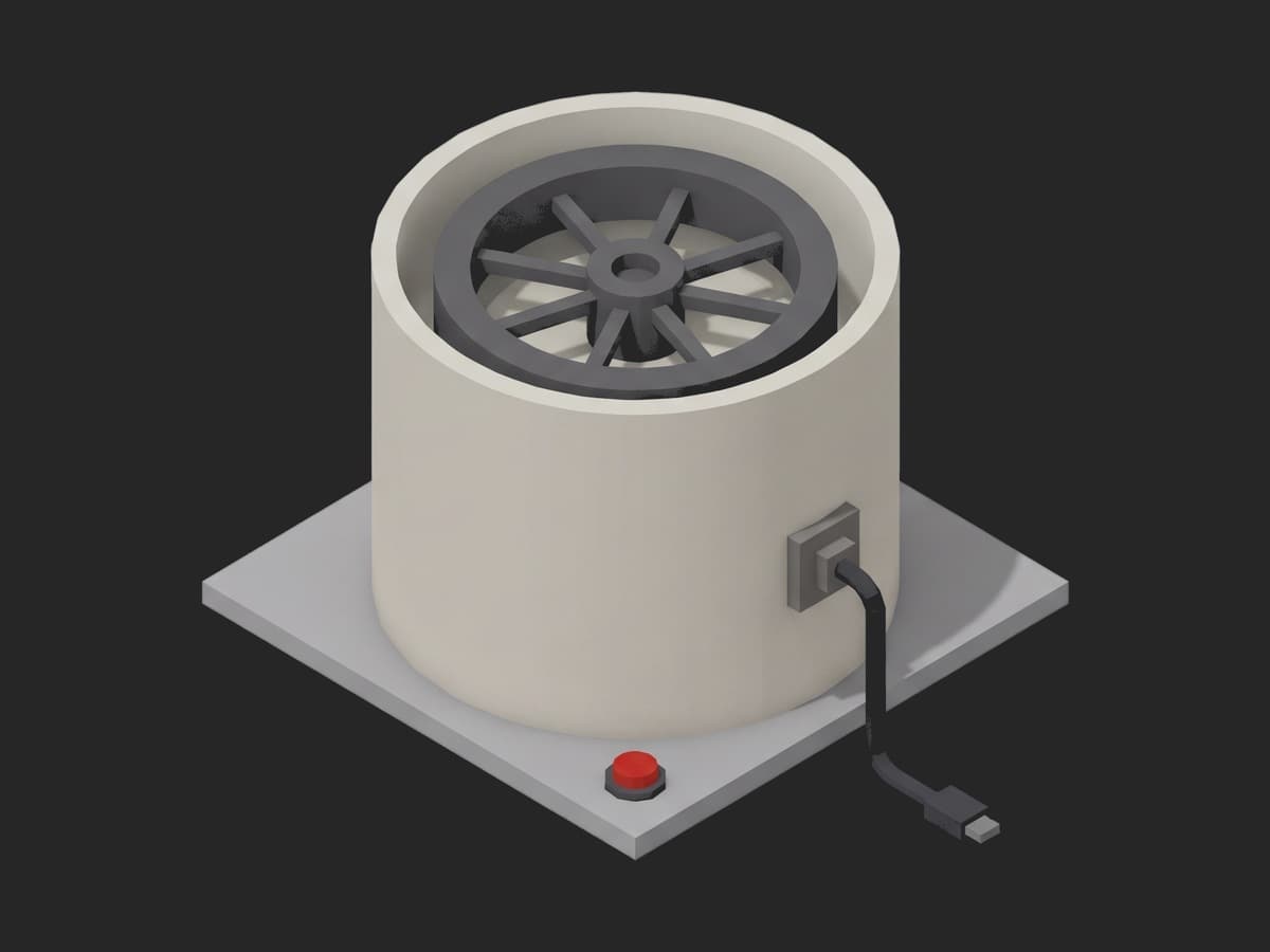
The unit under test with its lid off: a rim-heavy flywheel on two bearings in a sealed can, one connector for power and telemetry. Everything the acceptance test measures is a property of the rotor and the two bearings.
The numbers are small. A 0.05 Nms-class wheel draws a few watts, its bearing drag is a few tenths of a milli-newton-metre, and its residual unbalance is a fraction of a gram-millimetre. Blue Canyon publishes a static unbalance under 1.2 g·mm and a dynamic unbalance under 20 g·mm² for its small wheels and ships the measured pair per serial (see Blue Canyon's reaction wheel data); NewSpace Systems quotes 4 W at 3000 rpm and 6 W at 6500 rpm steady state on a comparable unit. The force the unbalance exports rises with the square of the wheel speed, so a rotor at 0.35 g·mm pushes about 140 mN on the mounting plate at 6000 rpm. Reading that on a dynamometer that resolves 3 mN takes an isolated table and a charge amplifier, and the sweep is the part of the test that tells a good bearing from a damaged one.
Test Purpose
The procedure records one acceptance record per wheel:
- Firmware, bearing temperature at rest, and the serial's cumulative vibration log against the bearing's qualification budget, before anything spins
- A one-hour wear-in through the speed profile with bearing drag and temperature logged, the settled drag validated
- Static and dynamic unbalance from the dynamometer against the vendor's per-serial acceptance figures
- Bus power at 3000 and 6000 rpm, then the bearing friction torque from a coast-down with the drive disabled
- Exported force over a 500 to 6000 rpm sweep, validated against an absolute ceiling and against the speed-squared law a balanced rotor follows
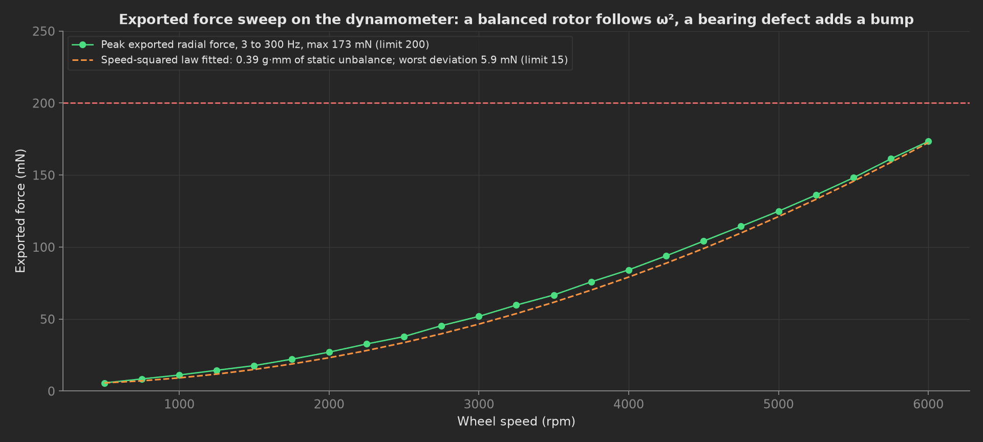
The mock wheel on the dynamometer: 173 mN at 6000 rpm against a 200 mN ceiling, and 5.9 mN worst deviation from the speed-squared law fitted to the sweep. A rotor that is simply out of balance moves the whole parabola up; a bearing with a damaged race adds a ball-pass line that does not scale with speed squared and shows as a bump the deviation aggregation catches.
The framework mechanics on show are a per-serial consumable budget validated in setup: and written to the unit metadata, a progress component on a time-scaled long phase with a timeout, two curves in one measurement each with its own aggregation and limit, a physical constant derived from a curve, a deviation-from-model aggregation next to an absolute one, and a teardown: that stops the wheel whatever happened.
Equipment & Setup
To accept reaction wheels on a production bench, the following are required:
- A multicomponent dynamometer under the wheel's mounting plate, with a charge amplifier and a DAQ that covers 3 to 300 Hz
- An isolated table that keeps the building out of the force measurement
- A bus power analyzer on the 28 V supply and the wheel's own telemetry link for speed, current and bearing temperature
- The Device Under Test (DUT): a 0.05 Nms-class reaction wheel, ±6000 rpm, 10 mNm
- A TofuPilot Framework procedure to sequence the wear-in, the balance reading, the power and coast-down, and the sweep
- The TofuPilot Dashboard to keep the vibration-exposure log per serial and trend drag, unbalance and exported force across the lot
Hardware Components
Dynamometer
The Kistler 9119AA1 is the reference for wheel micro-vibration: a three-component force plate with a threshold under 2 mN on Fx and Fy, three moment channels, and a natural frequency high enough that the 3 to 300 Hz band of interest sits well below it. A 5070A charge amplifier conditions the six piezo channels and the DAQ samples at 3200 S/s. The same plate reads the once-per-rev force and moment at balancing speed, which is where the static and dynamic unbalance come from, and the broadband force during the sweep. Anything that resolves a few mN at 100 Hz on a stiff plate does the job; what does not work is an accelerometer on the housing, because it reads the wheel's own response rather than what the wheel exports.
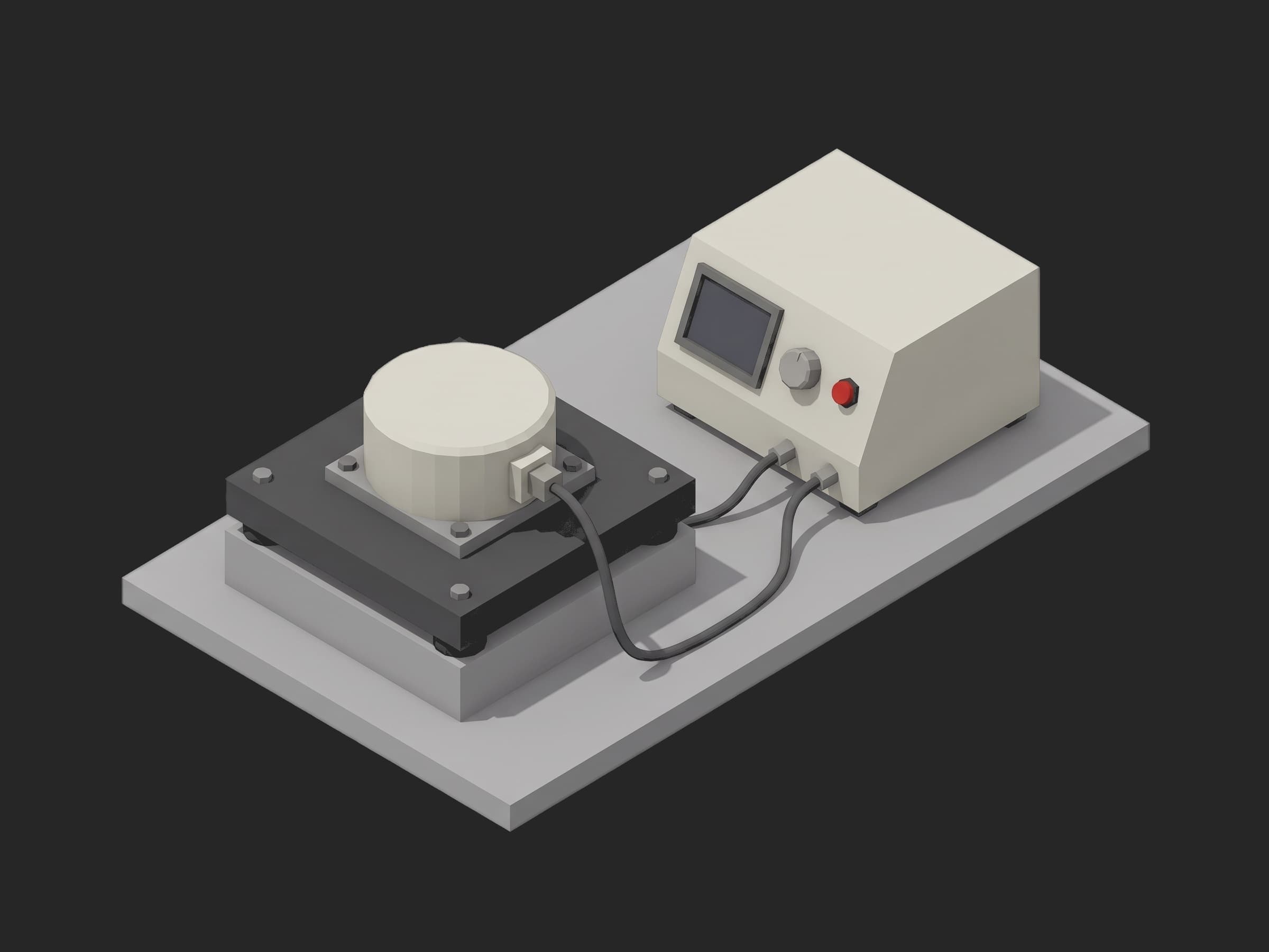
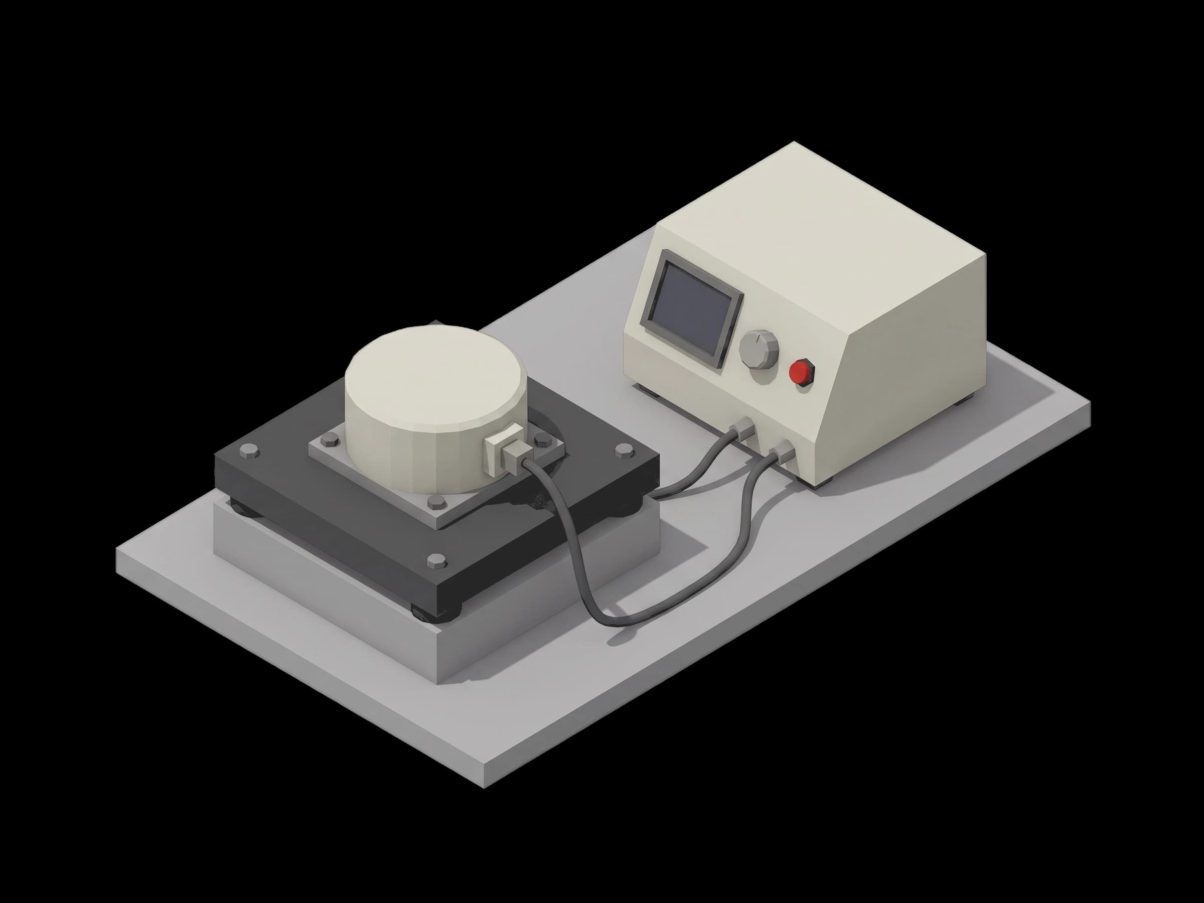
The bench: the wheel bolted flat on the dynamometer plate on its isolation block, the power analyzer and telemetry interface beside it. The plate's own mass and the block's stiffness set the noise floor of the whole test.
Wheel Telemetry and Bus Power
The wheel reports speed, motor current and bearing temperature over its serial link at a few hertz; the procedure reads all three during the wear-in and at each step of the sweep. A Yokogawa WT-class analyzer on the 28 V bus gives the steady-state power at each speed, the number the spacecraft's power budget uses. Bearing temperature is the second output of the wear-in: a bearing whose lubricant is distributed runs cooler, and a bearing that climbs past the limit during an hour at 6000 rpm is not going to survive a mission.
Wear-In and the Vibration Log
SMC-S-016 lists wear-in as a required acceptance test for moving mechanical assemblies, and a wheel's bearings need the hour through the speed profile before the drag, the power and the coast-down mean anything. The second bookkeeping item is the cumulative vibration exposure of the bearings: the wheel's ICD caps how many seconds of acceptance vibration the bearings may see on the ground so that ground plus launch stays under what the bearing was qualified to. The procedure reads that log per serial in setup and refuses to proceed on a wheel that has already spent its allowance. ECSS-E-ST-10-03C leaves the micro-vibration characterisation to the customer's requirements, so the exported-force limits here are the wheel's own, not a standard's.
Where the Limits Come From
The unbalance limits are the vendor's published acceptance figures for this wheel class: 1.2 g·mm static and 20 g·mm² dynamic. The settled drag limit of 0.30 mNm, the 0.35 mNm friction torque from the coast-down, and the 4.5 W and 7.5 W power ceilings sit above the vendor's steady-state curve with margin for a warm bench. The 200 mN exported-force ceiling is what a rotor at the unbalance limit pushes at full speed plus the bearing's contribution, and the 15 mN deviation limit is about five times the dynamometer's resolution. A customer sets the exported-force numbers from the spacecraft's micro-vibration budget, then tightens the deviation limit from the distribution the dashboard shows after a few dozen wheels.
Test Procedure
Overview
The procedure maps the acceptance test onto the framework's three stages. Identification and the vibration budget live in setup: so a wheel that fails the gate never spins. Stopping the wheel and reading the bearing temperature live in teardown: so the bench is safe to unload whether the test passed or not.
- Setup: firmware, bearing temperature at rest, vibration log against the budget.
- Main: one-hour wear-in through 1000, 3000, +6000 and -6000 rpm, drag and temperature logged.
- Main: static and dynamic unbalance from the dynamometer.
- Main: bus power at 3000 and 6000 rpm, coast-down from 6000 rpm, friction torque from the deceleration.
- Main: exported force at each speed from 500 to 6000 rpm, checked against the speed-squared law.
- Teardown: wheel stopped, bearing temperature read.
Every metric validates against limits declared in procedure.yaml, and results stream to TofuPilot for per-serial trending across the lot.
Why TofuPilot Framework?
TofuPilot Framework is a YAML + Python test framework built for hardware manufacturing. Instead of writing all your test logic, measurements, and limits inside Python code, you describe what the test does in a procedure.yaml file, and how in small Python phase files. The framework handles:
- Automatic Python environment management (via
uv) - Operator UI (no frontend code needed)
- Measurement validation and live charts
- Process isolation between phases and equipment plugs
Project Structure
You can find the full source on GitHub. The WheelBench plug is a mock of the wheel's telemetry link, the power analyzer and the dynamometer together, synthesizing a healthy wheel with 0.35 g·mm of static unbalance, bearings that settle from 0.31 to 0.19 mNm during the wear-in, and an exported force that follows the speed-squared law with the bearing's ball-pass harmonic on top, so the procedure runs end-to-end without a wheel or a dynamometer connected.
tofupilot run .For CI or bench automation, the same run executes headless:
tofupilot run . --no-tui --no-kiosk --jsonThe Procedure File
procedure.yaml declares the unit, the bench plug, and the three stages with every measurement and limit:
procedure.yaml · 171 lines
name: Reaction Wheel Acceptance Testversion: 0.1.0description: Acceptance test of a smallsat reaction wheel. Telemetry and vibration-exposure log in setup, time-scaled one-hour wear-in with bearing drag and temperature, static and dynamic unbalance on the dynamometer, bus power at two speeds and bearing friction from a coast-down, exported force over a speed sweep against the speed-squared law.unit: auto_identify: true serial_number: description: "Scan the wheel's housing label" placeholder: "RW-050-0000" pattern: "^RW-050-\\d{4}$" default_value: "RW-050-0312" part_number: default_value: "RW-050-28V" batch_number: default_value: "LOT-2026-09"plugs: - name: Wheel Bench description: "Wheel telemetry over RS-422, bus power analyzer, Kistler dynamometer under the mounting plate (mock, one plug per bench)" python: plugs.wheel_bench:WheelBench key: benchsetup: - name: Identify key: identify python: phases.identify measurements: - name: Firmware Version key: firmware_version validators: - {operator: matches, expected_value: "^1\\.\\d+\\.\\d+$"} - name: Bearing Temperature Start key: bearing_temp_start_c unit: °C validators: - {operator: ">=", expected_value: 18.0} - {operator: "<=", expected_value: 26.0} - name: Vibration Log key: vibration_log_s unit: s description: Cumulative acceptance vibration already on this serial; the bearing's qualification budget for acceptance plus launch is finite and the ICD says so. validators: - {operator: "<=", expected_value: 1800.0}main: - name: Run In key: run_in python: phases.run_in timeout: 2h ui: components: - key: run_in_progress type: progress label: "Wear-in" description: "60 min through 1000, 3000, +6000, -6000 rpm" default_value: 0 max: 100 measurements: - name: Wear-In key: wear_in title: Bearing drag torque and temperature through the wear-in x_axis: legend: Time unit: min y_axis: - legend: Drag key: drag unit: mNm aggregations: - type: final_mnm unit: mNm validators: - {operator: "<=", expected_value: 0.30} - legend: Bearing temperature key: temperature unit: °C aggregations: - type: max_c unit: °C validators: - {operator: "<=", expected_value: 45.0} - name: Balance key: balance python: phases.balance depends_on: [run_in] measurements: - name: Static Unbalance key: static_unbalance_gmm unit: g·mm description: Vendor acceptance figure for this wheel class, shipped per serial. validators: - {operator: "<=", expected_value: 1.2} - name: Dynamic Unbalance key: dynamic_unbalance_gmm2 unit: g·mm² validators: - {operator: "<=", expected_value: 20.0} - name: Power And Friction key: power_and_friction python: phases.power_and_friction depends_on: [balance] timeout: 15m measurements: - name: Power At 3000 rpm key: power_3000_w unit: W validators: - {operator: "<=", expected_value: 4.5} - name: Power At 6000 rpm key: power_6000_w unit: W validators: - {operator: "<=", expected_value: 7.5} - name: Coast-Down key: coast_down title: Speed after the drive is disabled at 6000 rpm x_axis: legend: Time unit: s y_axis: - legend: Speed key: speed unit: rpm aggregations: - type: friction_mnm unit: mNm validators: - {operator: "<=", expected_value: 0.35} - type: duration_s unit: s validators: - {operator: ">=", expected_value: 120.0} - name: Exported Force key: exported_force python: phases.exported_force depends_on: [power_and_friction] timeout: 15m measurements: - name: EFT key: eft title: Peak exported radial force, 3 to 300 Hz, against wheel speed x_axis: legend: Speed unit: rpm y_axis: - legend: Force key: force unit: mN aggregations: - type: max_mn unit: mN validators: - {operator: "<=", expected_value: 200.0} - type: max_deviation_mn unit: mN validators: - {operator: "<=", expected_value: 15.0}teardown: - name: Stop key: stop python: phases.stop measurements: - name: Bearing Temperature End key: bearing_temp_end_c unit: °C validators: - {operator: "<=", expected_value: 45.0}Framework features to notice:
- A consumable budget in setup.
vibration_log_s <= 1800is not a property of the wheel's performance; it is how much of the bearing's ground allowance this serial has spent. It gates the run and lands on the unit metadata so the dashboard shows it per serial. - Progress on a long phase. The wear-in is an hour on real hardware; the
progresscomponent and thetimeout: 2hmake the phase visible and bounded without any UI code. - Two curves, two limits.
wear_inrecords drag and bearing temperature against time; each curve carries its own aggregation,final_mnmon one andmax_con the other, with its own validator. - A constant from a curve.
coast_down.friction_mnmis the deceleration slope of the first 60 s times the rotor's inertia; the framework stores the curve and validates the derived number. - Model deviation next to an absolute.
eft.max_mn <= 200bounds what the wheel exports;max_deviation_mn <= 15bounds how far the sweep departs from the speed-squared law a balanced rotor obeys, which is what a bearing defect changes.
Identify
The setup phase reads the firmware and the bearing temperature at rest over the telemetry link, then reads the serial's cumulative vibration log and writes it to the unit metadata. A wheel that has already spent its acceptance vibration allowance fails here and never spins:
from utils.recipe import VIBRATION_LIFE_Sdef identify(measurements, bench, unit, log): """Setup: telemetry link, firmware, bearing temperature at rest, and the serial's cumulative vibration log against the bearing budget; a wheel that has already spent its acceptance vibration allowance is not re-vibrated whatever the sequence says.""" ident = bench.identify() measurements.firmware_version = ident["firmware"] measurements.bearing_temp_start_c = ident["bearing_temp_c"] vib = bench.vibration_log_s() measurements.vibration_log_s = vib unit.metadata["vibration_exposure_s"] = vib log.info(f"Wheel {unit.serial_number}: fw {ident['firmware']}, bearings at {ident['bearing_temp_c']} C, {vib:.0f} s of vibration logged against a {VIBRATION_LIFE_S:.0f} s budget")Run In
One call returns the hour of wear-in as three lists; the phase converts time to minutes, records drag and bearing temperature as two curves of one measurement, and computes the settled drag as the mean of the last five minutes:
phases/run_in.py · 21 lines
import numpy as npfrom utils.recipe import RUN_IN_MINUTES, RUN_IN_SPEEDS_RPMdef run_in(measurements, bench, ui, log): """Wear-in per SMC-S-016: the wheel through its speed profile for an hour, bearing drag and temperature logged. The drag at the end is the number the coast-down and the power test are judged against.""" cap = bench.run_in(RUN_IN_SPEEDS_RPM, RUN_IN_MINUTES) ui.run_in_progress = 100 drag = np.array(cap["drag_mnm"]) t = np.array(cap["time_s"]) final = float(drag[t >= t[-1] - 300.0].mean()) measurements.wear_in.x_axis = (t / 60.0).round(2).tolist() measurements.wear_in.y_axis.drag = cap["drag_mnm"] measurements.wear_in.y_axis.drag.aggregations.final_mnm = final measurements.wear_in.y_axis.temperature = cap["bearing_temp_c"] measurements.wear_in.y_axis.temperature.aggregations.max_c = float(max(cap["bearing_temp_c"])) log.info(f"Wear-in {RUN_IN_MINUTES:.0f} min: drag {drag[0]:.3f} -> {final:.3f} mNm, bearings to {max(cap['bearing_temp_c']):.1f} C")Balance
The dynamometer at a fixed balancing speed gives the once-per-rev force and moment, which are the static and dynamic unbalance. The two scalars go straight against the vendor's acceptance figures:
def balance(measurements, bench, log): """Static and dynamic unbalance from the dynamometer at balancing speed. The vendor ships these two numbers per serial; the limits are the vendor's own acceptance figures.""" bal = bench.balance_measurement() measurements.static_unbalance_gmm = bal["static_gmm"] measurements.dynamic_unbalance_gmm2 = bal["dynamic_gmm2"] log.info(f"Static {bal['static_gmm']:.2f} g-mm, dynamic {bal['dynamic_gmm2']:.1f} g-mm2")Power And Friction
Bus power at 3000 and 6000 rpm from the analyzer, then the drive is disabled at 6000 rpm and the speed logged until 500 rpm. The slope of the first 60 s times the rotor's inertia is the bearing friction torque at high speed, the number that separates a dry or damaged bearing from a good one:
phases/power_and_friction.py · 31 lines
import numpy as npfrom utils.recipe import COAST_DOWN_FROM_RPM, MOMENTUM_NMS_AT_MAX, MAX_SPEED_RPM, POWER_W_MAXdef power_and_friction(measurements, bench, log): """Steady-state bus power at two speeds, then a coast-down from full speed with the drive disabled: the deceleration times the inertia is the bearing friction torque, the number that tells a dry or a damaged bearing from a good one.""" for rpm in sorted(POWER_W_MAX): bench.spin_to(rpm) p = bench.steady_power_w(rpm) setattr(measurements, f"power_{int(rpm)}_w", p) log.info(f"{rpm:.0f} rpm: {p:.2f} W on the bus") bench.spin_to(COAST_DOWN_FROM_RPM) coast = bench.coast_down(COAST_DOWN_FROM_RPM) t = np.array(coast["time_s"]) w = np.array(coast["speed_rpm"]) * 2 * np.pi / 60.0 inertia = MOMENTUM_NMS_AT_MAX / (MAX_SPEED_RPM * 2 * np.pi / 60.0) # Friction torque at high speed from the first 60 s of the coast-down. m = t <= 60.0 slope, _ = np.polyfit(t[m], w[m], 1) friction_mnm = float(-slope * inertia * 1000.0) measurements.coast_down.x_axis = coast["time_s"] measurements.coast_down.y_axis.speed = coast["speed_rpm"] measurements.coast_down.y_axis.speed.aggregations.friction_mnm = friction_mnm measurements.coast_down.y_axis.speed.aggregations.duration_s = float(t[-1]) log.info(f"Coast-down from {COAST_DOWN_FROM_RPM:.0f} rpm: {t[-1]:.0f} s to 500 rpm, friction {friction_mnm:.3f} mNm at high speed")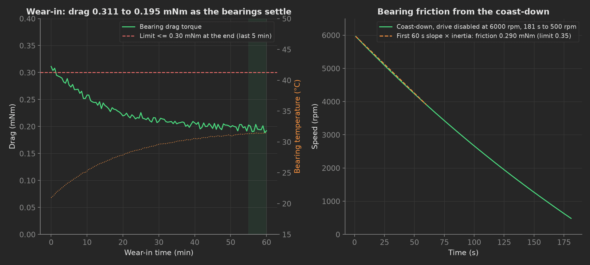
The mock wheel's hour: drag settles from 0.311 to 0.195 mNm as the lubricant distributes, bearings warm to 31.5 °C, and the coast-down from 6000 rpm takes 181 s with a friction torque of 0.290 mNm from the first minute. The bus draws 2.53 W at 3000 rpm and 2.90 W at 6000 rpm. A wheel whose drag does not settle, or whose coast-down is short, has a bearing problem the sweep will then locate.
Exported Force
At each speed of the sweep the phase reads the peak exported radial force in the 3 to 300 Hz band, fits the speed-squared law to the whole sweep, and reports the maximum and the worst deviation from the fit:
phases/exported_force.py · 25 lines
import numpy as npfrom utils.recipe import EFT_SWEEP_RPMdef exported_force(measurements, bench, log): """Exported force on the dynamometer at each speed of the sweep, 3 to 300 Hz. A balanced rotor's force rises with speed squared; a bearing defect adds a line that does not, and shows as a bump in the curve.""" force = [] for rpm in EFT_SWEEP_RPM: bench.spin_to(rpm) force.append(bench.exported_force_mn(rpm)) bench.stop() force = np.array(force) rpm = np.array(EFT_SWEEP_RPM, dtype=float) # Fit the unbalance law and report the worst deviation from it. k, _ = np.polyfit(rpm ** 2, force, 1) resid = force - (k * rpm ** 2 + force[0] - k * rpm[0] ** 2) measurements.eft.x_axis = EFT_SWEEP_RPM measurements.eft.y_axis.force = force.tolist() measurements.eft.y_axis.force.aggregations.max_mn = float(force.max()) measurements.eft.y_axis.force.aggregations.max_deviation_mn = float(np.abs(resid).max()) log.info(f"Exported force {force.min():.1f}..{force.max():.1f} mN over {rpm.min():.0f}..{rpm.max():.0f} rpm, worst deviation from the speed-squared law {np.abs(resid).max():.1f} mN")Mock Plug
WheelBench stands in for the wheel's telemetry link, the bus power analyzer and the dynamometer. It draws a rotor with 0.35 g·mm of static and 9 g·mm² of dynamic unbalance, bearing drag that decays exponentially from 0.31 to 0.19 mNm with a 15-minute time constant while the bearings warm from 21 to 32 °C, bus power as the drag times the speed over the drive efficiency plus 2.4 W of electronics, a coast-down integrated at 1 Hz from the drag over the inertia, and an exported force that is the unbalance times the speed squared plus a small bearing term. The wear-in is time-scaled and returns in one call. Every method returns plain Python types because plug calls cross a JSON boundary; a measurement read back from measurements.<key> returns a proxy, so the phases keep locals for their log lines.
On a real station, the class speaks the wheel's protocol over pyserial for speed, current and bearing temperature, SCPI to the power analyzer over pyvisa, and reads the six dynamometer channels through the charge amplifier and the DAQ with a 3 to 300 Hz band. Set TIME_SCALE = 1.0 in utils/recipe.py for the real hour of wear-in, keep the vibration-exposure log in the dashboard per serial and add every acceptance vibration run to it, and take the unbalance limits from the vendor's data sheet for the wheel class. The phases, measurements and limits stay the same.