
Get the complete source, dependencies and setup instructions from the template repository.
Open the source on GitHubIntroduction
The LRU and the ARINC 429 Bus
An LRU (line-replaceable unit) is a self-contained box in the avionics bay, swapped as a whole during maintenance and sent to a component shop for repair. Many LRUs sit on the aircraft's DC power distribution and report their status over ARINC 429, the standard digital databus for commercial avionics. A power distribution or bus control unit is a good example: it takes redundant 28 V DC feeds and transmits fault and status words to the flight computers and the central maintenance system.
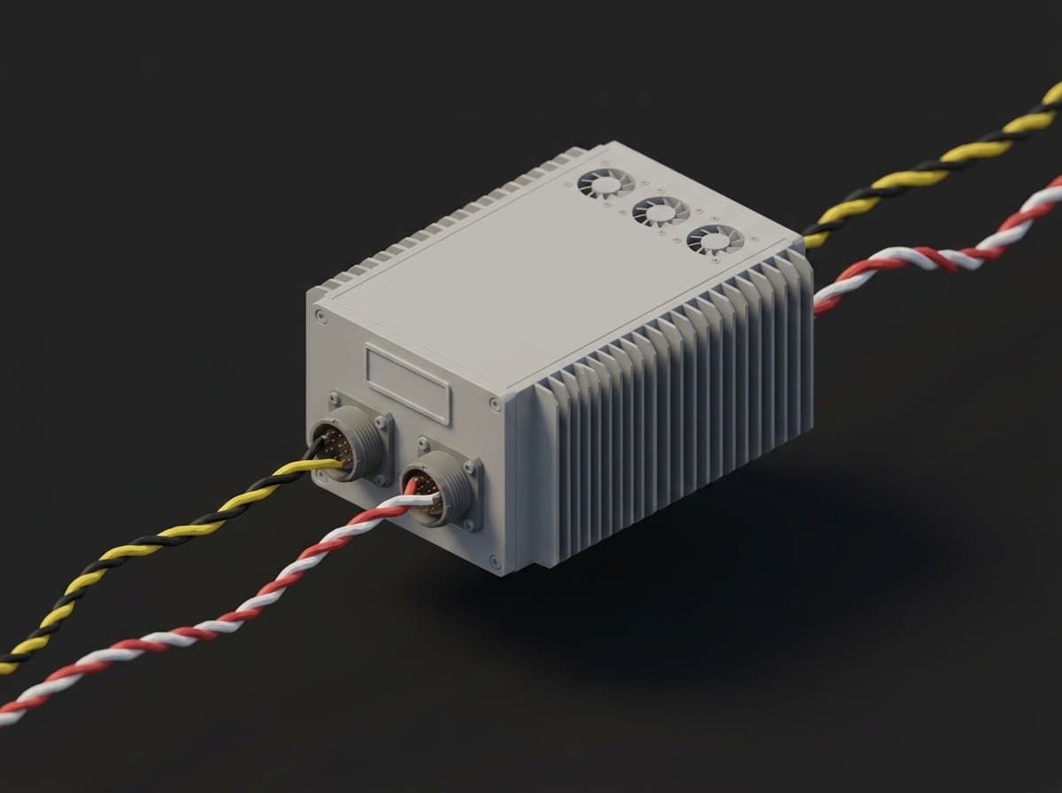
A typical LRU: sealed aluminium housing, circular connectors carrying both 28 V buses and the ARINC 429 pairs, swapped as one part on the aircraft and tested as one part in the shop.
Two properties of this class of unit shape the whole test. First, it has two segregated power inputs, a primary and a backup bus, electrically and mechanically separated so the loss of one supply cannot take the unit down. Aircraft DC power is nominally 28 V DC, produced by transformer-rectifier units from the 115 V AC buses. Second, it talks over ARINC 429, so the acceptance test has to speak that protocol to stimulate the unit and read it back.
ARINC 429 is a unidirectional, point-to-point databus: one transmitter drives up to twenty receivers on a twisted shielded pair, and a bidirectional link needs two buses. It runs at either low speed (12.5 kbit/s) or high speed (100 kbit/s), and the two rates cannot share a bus. Each message is a 32-bit word with five fields:
| Bits | Field | Purpose |
|---|---|---|
| 1–8 | Label | Octal code identifying the data type |
| 9–10 | SDI | Source/destination identifier |
| 11–29 | Data | The payload (BNR, BCD, or discrete) |
| 30–31 | SSM | Sign/status matrix (normal, failure warning, no-computed-data, functional test) |
| 32 | Parity | Odd parity over the word |
The differential signal swings ±10 V between the two legs, with defined high, null, and low bands and a specified rise/fall time (1.5 ± 0.5 µs at high speed, 10 ± 5 µs at low speed). These are real, measurable pass/fail quantities on the bench.
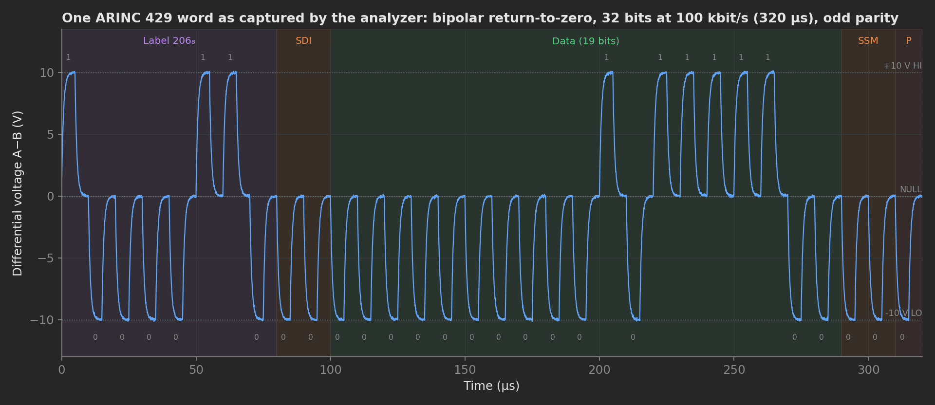
Label 206 as the mock analyzer captures it: bipolar return-to-zero, every bit spends its first half at +10 V or -10 V and its second half at null, 32 bits in 320 µs at high speed, odd parity in bit 32.
Purpose of the Test
When a removed unit arrives at the shop, the acceptance test per the OEM's CMM (component maintenance manual) has to prove three things before the unit is released on an EASA Form 1: it draws the right current on each bus, it transmits every expected ARINC 429 label correctly, and it fails over from one power bus to the other without dropping its output. This template builds that test as a structured, automated procedure so that every measured value, not just the pass/fail verdict, is recorded against the unit's serial number. The per-unit fingerprint:
- Bus A and bus B current at matched 28.0 V, and their mismatch
- Label word error rate and response latency on the ARINC 429 output
- Bus waveform: one captured word with its rise time and HI level
- Output accuracy of the decoded engineering-unit value
- Failover: word error rate and bus B current with bus A cut
- Power-down state of both buses, recorded by the teardown
The reason to keep the values matters as much as the test itself. A large share of avionics LRUs that come back to the shop test No Fault Found: field data puts avionics NFF as high as 20 percent of removals, and at the repair-bench level figures upward of 70 percent have been reported for some unit types. An NFF unit consumes a full bench cycle and returns to stock having taught the shop nothing, unless the measurements behind the pass are trended over time. ARINC 672 exists specifically as an industry guideline for reducing NFF, and structured test data is the raw material for it.
Beyond the avionics content, this template demonstrates four framework mechanics: one driver class with one thin subclass per instrument address for the two identical supplies, a multi-dimensional measurement with custom aggregations computed in Python and validated in YAML, a derived measurement combining two plugs, and a teardown stage that powers the unit down whatever happened before.
Equipment & Setup
To run a dual-bus ARINC 429 acceptance test you will need:
- Two identical programmable DC supplies, one per power bus, each set to 28.0 V.
- An ARINC 429 bus analyzer with transmit ports (to stimulate the unit's receive labels), receive ports (to capture and time-tag the unit's transmit labels), and a waveform capture on the pair.
- A bench digital multimeter (DMM) for output voltage and insulation/dielectric checks.
- The device under test (DUT): the LRU, wired to both supplies and to the analyzer's bus pairs.
- A TofuPilot Framework procedure to power the unit, drive the analyzer, evaluate every measurement against its CMM limits, and provide a global pass/fail status.
- The TofuPilot Dashboard to store results for traceability and analytics.
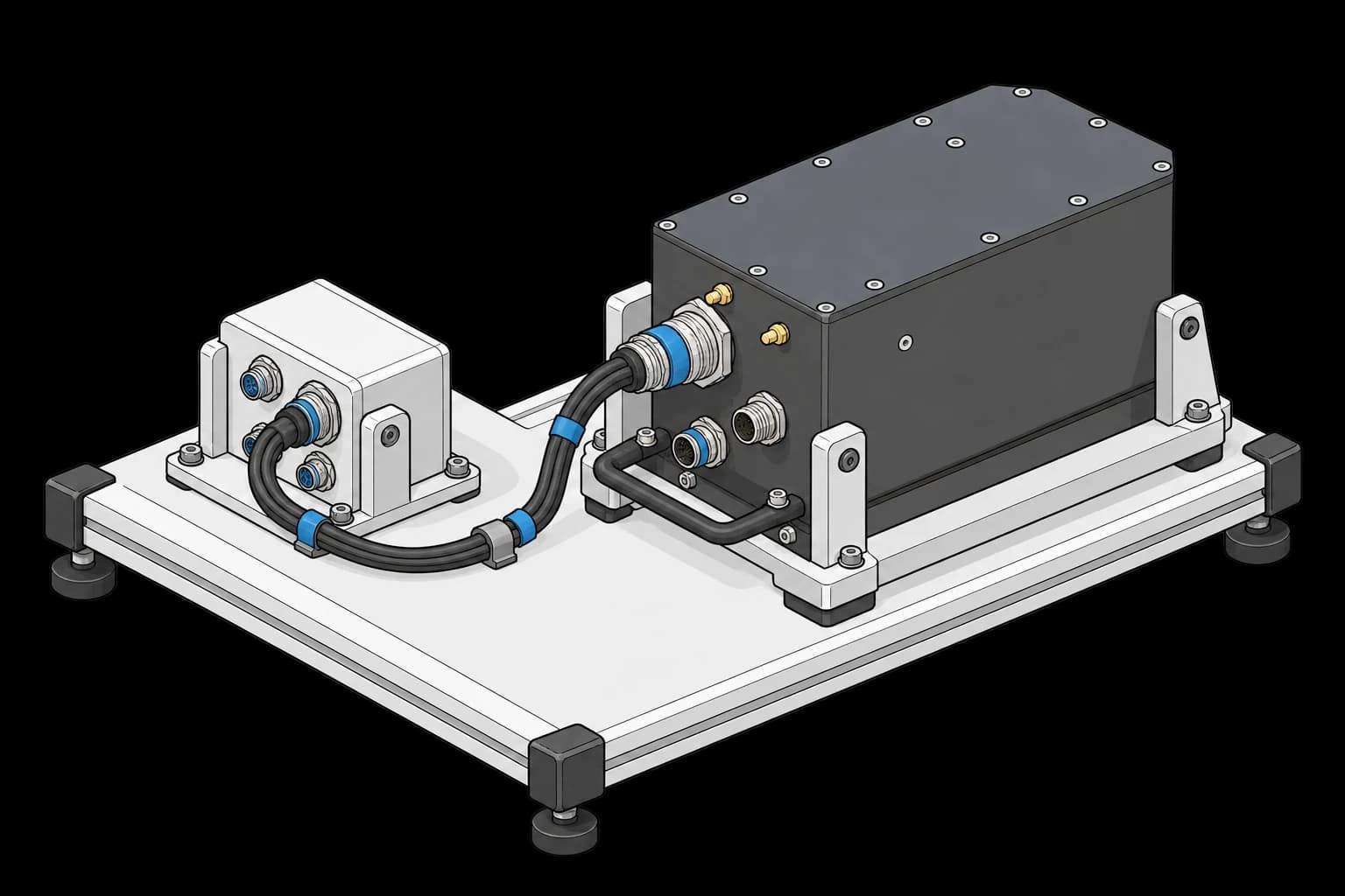
The fixture secures the avionics unit and exposes its connector harnesses. The power supplies, ARINC analyzer and test computer are not shown.
Why Two Identical Supplies
The unit under test has two power inputs by design, for redundancy, so the bench must feed each one from its own independent supply. Using two supplies of the same model, held at a matched 28.0 V, means any difference in current draw between bus A and bus B is a property of the unit, not an artifact of two mismatched instruments. It also lets the test prove the failover directly: cut supply A, and confirm the unit rides through on supply B without interrupting its ARINC 429 output.
A common bench choice is a pair of 3-channel programmable supplies (30 V / 3 A per channel, sub-0.1 percent programming accuracy, SCPI-controllable over LAN, USB, or RS-232), for example two Rigol DP832-class units. The important point for the software is not the model but that there are two of them, identical, each at a different address.
ARINC 429 Analyzer
Production benches use a PCI/PXI or USB ARINC 429 interface with several transmit and receive channels (Astronics Ballard, AIM, or Holt evaluation boards). Word error rate and latency come from the channel's receive FIFO with hardware time tags; the waveform comes from an oscilloscope probe across the pair, or from the analyzer's own capture on interfaces that provide it. The template's mock synthesizes both from the same 32-bit encoder so the procedure runs without hardware.
Test Procedure
Overview
After connecting the unit to both supplies and to the analyzer pairs, the procedure runs:
- Power both buses to 28.0 V and record per-bus current and their mismatch.
- Measure the label 206 word error rate and response latency, capture one word and compute its rise time and HI level.
- Decode an engineering-unit output and compare it to the commanded value.
- Cut bus A, confirm the label error rate holds at zero on bus B alone, record bus B current.
- Teardown: both supplies to 0 V, confirm both buses read below 0.5 V.
- Validate every metric against its declared limits and stream the run to TofuPilot.
Why TofuPilot Framework
TofuPilot Framework is a YAML + Python test framework built for hardware. You describe what the test does in a procedure.yaml file and how in small Python phase and plug files. The framework handles Python environment management, the operator UI, measurement validation and live charts, and process isolation between phases and each piece of equipment.
Project Structure
The plugs are mocks: the supplies return fixed currents with noise, the analyzer synthesizes a word on the bus. Run it with tofupilot run . --no-tui --no-kiosk --json. You can find the full source on GitHub.
The Procedure File
This is the exact file the template ships, verified end to end with the CLI. It identifies the unit, declares the four instruments as plugs, lays out four main phases with their measurements and CMM limits, and a teardown phase:
procedure.yaml136 lines
name: ARINC 429 LRU Acceptance Testversion: 0.1.0description: Functional acceptance test for a dual-bus avionics LRU, using two identical 28V supplies, an ARINC 429 bus analyzer, and a DMM.unit: auto_identify: true serial_number: description: "Serial from the LRU nameplate" placeholder: "LRU000000" pattern: "^LRU\\d{6}$" default_value: "LRU000042" part_number: default_value: "622-1234-001"plugs: - name: PSU Bus A description: 28V DC supply for redundant bus A (mock Rigol DP832-class, VISA 192.168.1.50) python: plugs.psu:PsuBusA key: psu_a - name: PSU Bus B description: 28V DC supply for redundant bus B (mock Rigol DP832-class, VISA 192.168.1.51) python: plugs.psu:PsuBusB key: psu_b - name: ARINC 429 Analyzer description: ARINC 429 bus analyzer for label capture, latency and waveform (mock) python: plugs.arinc:Arinc429Analyzer key: arinc - name: DMM description: Digital multimeter for output accuracy (mock) python: plugs.dmm:Dmm key: dmmmain: - name: Power Up key: power_up python: phases.power_up measurements: - name: Bus A Current key: bus_a_current unit: A validators: - {operator: "<=", expected_value: 1.8} - name: Bus B Current key: bus_b_current unit: A validators: - {operator: "<=", expected_value: 1.8} - name: Bus Current Mismatch key: bus_current_mismatch unit: A description: Absolute difference between the two bus currents at matched 28.0 V. Two identical supplies make this a property of the unit. validators: - {operator: "<=", expected_value: 0.2} - name: Bus Integrity key: bus_integrity python: phases.bus_integrity depends_on: [power_up] measurements: - name: Label Word Error Rate key: word_error_rate description: Fraction of label 206 words received corrupted or missing over the capture window. validators: - {operator: "<=", expected_value: 0.00001} - name: Response Latency key: response_latency unit: ms validators: - {operator: "<=", expected_value: 50} - name: Label 206 Waveform key: label_waveform title: ARINC 429 word on the bus (label 206, high speed) description: Differential voltage of one captured 32-bit word, bipolar return-to-zero at 100 kbit/s. x_axis: legend: Time unit: µs y_axis: - legend: Differential voltage key: v_diff unit: V aggregations: - type: rise_time_us unit: µs validators: - {operator: ">=", expected_value: 1.0} - {operator: "<=", expected_value: 2.0} - type: high_level_v unit: V validators: - {operator: ">=", expected_value: 9.0} - {operator: "<=", expected_value: 11.0} - name: Output Accuracy key: output_accuracy python: phases.output_accuracy depends_on: [bus_integrity] measurements: - name: Output Error key: output_error unit: "%" validators: - {operator: ">=", expected_value: -0.5} - {operator: "<=", expected_value: 0.5} - name: Bus Failover key: bus_failover python: phases.bus_failover depends_on: [output_accuracy] measurements: - name: Failover Word Error Rate key: failover_word_error_rate description: Label 206 error rate while bus A is cut and the unit rides on bus B alone. validators: - {operator: "<=", expected_value: 0.00001} - name: Bus B Current On Failover key: bus_b_failover_current unit: A description: Bus B carries the whole unit once bus A is gone. validators: - {operator: "<=", expected_value: 3.0}teardown: - name: Power Down key: power_down python: phases.power_down measurements: - name: Bus A Off Voltage key: bus_a_off_voltage unit: V validators: - {operator: "<=", expected_value: 0.5} - name: Bus B Off Voltage key: bus_b_off_voltage unit: V validators: - {operator: "<=", expected_value: 0.5}The limits shown are illustrative; on a real bench they come from the unit's CMM. Framework features to notice:
- Two plugs, one driver:
psu_aandpsu_bpoint at two subclasses of the same driver class; each phase that needs both names them as two parameters. - Multi-dimensional measurement with custom aggregations:
label_waveformstores the captured word as an x/y series;rise_time_usandhigh_level_vare free-named aggregations that Python computes on the series and the YAML validates against the bus spec. - Derived measurement:
bus_current_mismatchis computed in the phase from two plug readings and validated like any other value. - Teardown stage:
power_downruns after the main phases whatever their outcome, so a failed unit is never left energized on the bench. - Unit serial pattern: the nameplate serial is validated against
^LRU\d{6}$before the run starts.
Controlling Two Identical Instruments
Here is the question that trips up most people setting up a multi-instrument bench: how do you drive two supplies of the same model without duplicating the driver code, and where do the addresses live?
The framework instantiates a plug by calling the class with no arguments, so the cleanest pattern is one shared driver class plus a thin subclass per address. The driver logic is written once; each subclass just fixes which physical instrument it is:
plugs/psu.py41 lines
import randomclass ProgrammablePsu: """Shared driver for a programmable DC supply at a given VISA address.""" def __init__(self, address, idle_current_a): self.address = address self._idle_current_a = idle_current_a self._volts = 0.0 self._extra_load_a = 0.0 # self.inst = pyvisa.ResourceManager().open_resource(address) print(f"Connected PSU at {self.address}") def set_voltage(self, volts): # self.inst.write(f":SOUR:VOLT {volts}") self._volts = float(volts) def measure_voltage(self): # return float(self.inst.query(":MEAS:VOLT?")) return self._volts + random.gauss(0.0, 0.01) def measure_current(self): # return float(self.inst.query(":MEAS:CURR?")) if self._volts < 18.0: return 0.0 return self._idle_current_a + self._extra_load_a + random.gauss(0.0, 0.01) def take_over_load(self, amps): """Mock only: the other bus dropped, this supply now carries its share.""" self._extra_load_a = float(amps)class PsuBusA(ProgrammablePsu): def __init__(self): super().__init__("TCPIP0::192.168.1.50::INSTR", idle_current_a=1.42)class PsuBusB(ProgrammablePsu): def __init__(self): super().__init__("TCPIP0::192.168.1.51::INSTR", idle_current_a=1.39)Each subclass is referenced as its own plug in the YAML, with its own key. The framework runs each plug in its own process and passes both into a phase by matching the parameter name to the plug key. So psu_a and psu_b are two independent connections sharing every line of driver code, and adding a third supply is three more lines.
Power Up
Both buses go to 28.0 V and the phase records what each one draws. Two identical supplies at matched voltage make the per-bus comparison meaningful, so the mismatch is a measurement in its own right:
def power_up(psu_a, psu_b, measurements, log): log.info("Powering redundant buses A and B to 28.0 V") psu_a.set_voltage(28.0) psu_b.set_voltage(28.0) i_a = psu_a.measure_current() i_b = psu_b.measure_current() log.info(f"Bus A {i_a:.2f} A, bus B {i_b:.2f} A") measurements.bus_a_current = i_a measurements.bus_b_current = i_b measurements.bus_current_mismatch = abs(i_a - i_b)Bus Integrity
The analyzer reports the label 206 error rate and the response latency, then captures one word on the pair. The phase pushes the raw samples into the multi-dimensional measurement and computes the two aggregations the YAML validates:
from utils.waveform import high_level, rise_timeLABEL = 0o206def bus_integrity(arinc, measurements, log): log.info("Checking ARINC 429 label integrity and latency") measurements.word_error_rate = arinc.measure_word_error_rate(LABEL) measurements.response_latency = arinc.measure_latency_ms() t_us, v_diff = arinc.capture_word(LABEL) measurements.label_waveform.x_axis = t_us measurements.label_waveform.y_axis.v_diff = v_diff measurements.label_waveform.y_axis.v_diff.aggregations.rise_time_us = rise_time(t_us, v_diff) measurements.label_waveform.y_axis.v_diff.aggregations.high_level_v = high_level(t_us, v_diff) log.info(f"Rise time {rise_time(t_us, v_diff):.2f} us, HI level {high_level(t_us, v_diff):.2f} V")The edge metrics live in a small utility module: the HI level is the mean of the settled top samples, the rise time is the 10-90 % crossing of the first null-to-HI edge:
utils/waveform.py19 lines
import numpy as npdef high_level(t_us, v_diff): """Mean of the settled HI half-bits (top 10 % of samples, noise-tolerant).""" v = np.asarray(v_diff) top = np.sort(v)[int(0.9 * v.size) :] return float(top.mean())def rise_time(t_us, v_diff): """10-90 % rise time of the first null -> HI transition, in microseconds.""" t = np.asarray(t_us) v = np.asarray(v_diff) high = high_level(t_us, v_diff) lo, hi = 0.1 * high, 0.9 * high i_lo = int(np.argmax(v >= lo)) i_hi = int(np.argmax(v >= hi)) return float(t[i_hi] - t[i_lo])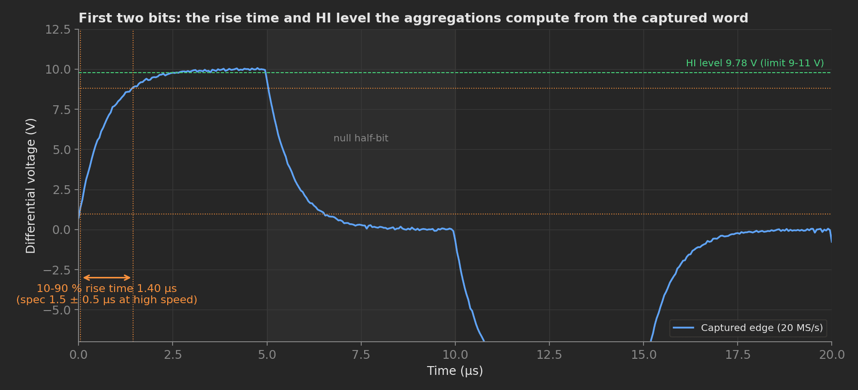
The two aggregations on the captured word: 1.40 µs rise time inside the 1 to 2 µs window, 9.78 V HI level inside the 9 to 11 V transmitter output band. A driver with a failing output stage shows up here as a slow edge or a sagging HI level long before the label stops decoding.
Output Accuracy
An engineering-unit output is decoded and compared to the commanded value:
def output_accuracy(dmm, measurements, log): log.info("Measuring output accuracy against reference") measurements.output_error = dmm.measure_output_error_pct()Bus Failover
The redundancy check is what a single-supply bench cannot do. With two independent supplies under software control, the phase drops bus A and confirms the unit holds its ARINC 429 output on bus B, and records how much current bus B carries alone:
LABEL = 0o206def bus_failover(psu_a, psu_b, arinc, measurements, log): log.info("Dropping bus A, confirming output holds on bus B") psu_a.set_voltage(0.0) psu_b.take_over_load(1.35) # mock: bus B now carries the unit alone measurements.failover_word_error_rate = arinc.measure_word_error_rate(LABEL) i_b = psu_b.measure_current() log.info(f"Bus B {i_b:.2f} A with bus A cut") measurements.bus_b_failover_current = i_b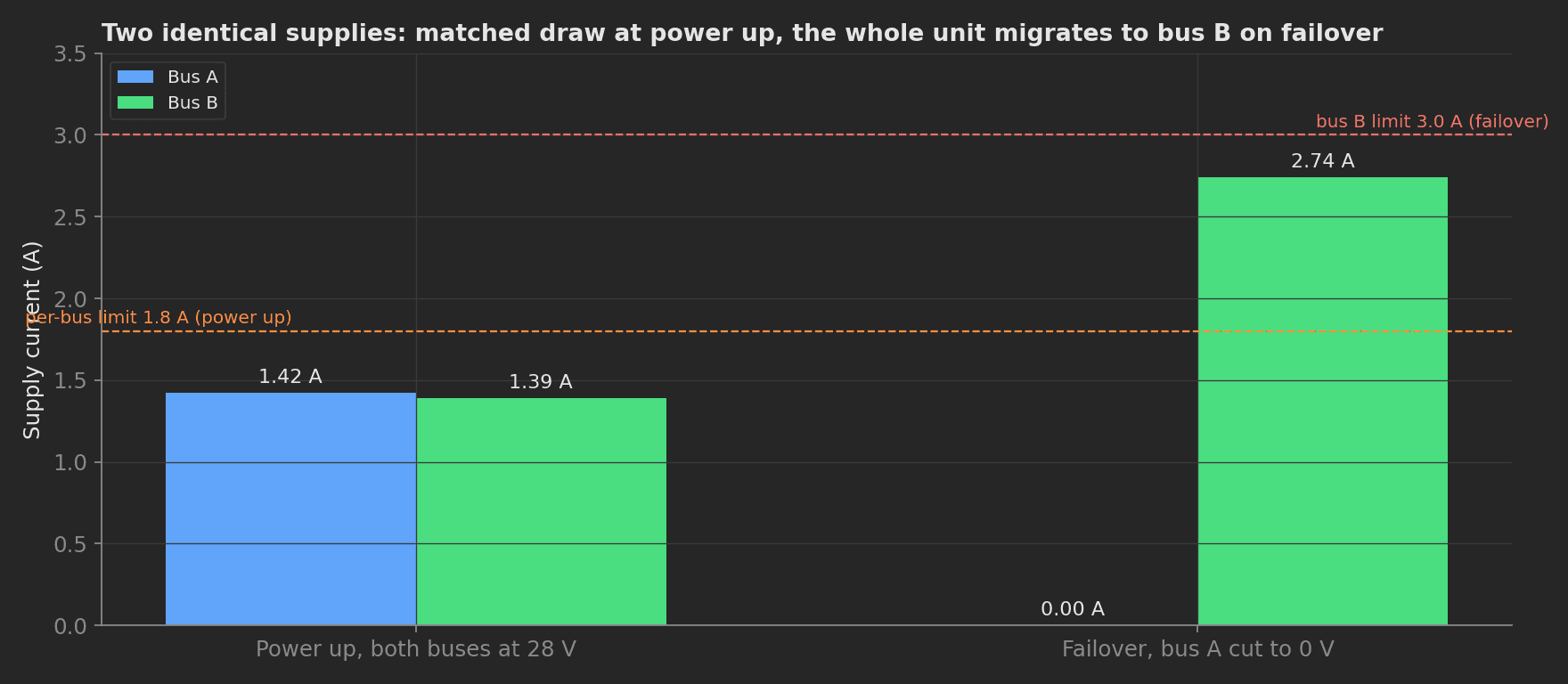
Currents through the run: matched draw at power up (0.05 A mismatch against a 0.2 A limit), then the whole unit on bus B once bus A is cut. Because each supply is its own plug, cutting one and watching the other is a two-line phase, not a bench rewire.
Power Down
The teardown always runs, even when a main phase failed, so no unit is left energized on the bench:
def power_down(psu_a, psu_b, measurements, log): """Teardown: always runs, so the unit is never left powered on the bench.""" log.info("Powering down both buses") psu_a.set_voltage(0.0) psu_b.set_voltage(0.0) measurements.bus_a_off_voltage = abs(psu_a.measure_voltage()) measurements.bus_b_off_voltage = abs(psu_b.measure_voltage())Mock Plugs
The analyzer mock synthesizes the word it "captures": the 32 bits come from a small encoder that builds the label, SDI, data, SSM and odd parity in transmission order, then the bipolar return-to-zero waveform is shaped with first-order edges at 20 MS/s so the rise-time aggregation has something real to measure:
def encode_word(label_octal, sdi, data, ssm): """Return the 32 bits of a word in transmission order (bit 1 first). Bits 1-8 label, transmitted MSB first (the label octal's high digit goes out first), bits 9-10 SDI, bits 11-29 data (LSB first), bits 30-31 SSM, bit 32 odd parity over bits 1-31. """ label = int(label_octal) & 0xFF bits = [(label >> (7 - i)) & 1 for i in range(8)] bits += [(sdi >> i) & 1 for i in range(2)] bits += [(data >> i) & 1 for i in range(19)] bits += [(ssm >> i) & 1 for i in range(2)] bits.append(0 if sum(bits) % 2 else 1) assert len(bits) == 32 return bitsRunning the procedure from its directory executes the five phases in order and validates every measurement:
→ Phase: Power Up→ Bus A 1.43 A, bus B 1.38 A✓ Phase Power Up: PASS→ Phase: Bus Integrity→ Rise time 1.40 us, HI level 9.78 V✓ Phase Bus Integrity: PASS→ Phase: Output Accuracy✓ Phase Output Accuracy: PASS→ Phase: Bus Failover→ Bus B 2.74 A with bus A cut✓ Phase Bus Failover: PASS→ Phase: Power Down✓ Phase Power Down: PASS✓ Run complete: PASSTo use it on a real bench, uncomment the pyvisa calls in plugs/psu.py and replace the analyzer mock with your interface's API; the phases, measurements, and limits stay exactly the same.