
Get the complete source, dependencies and setup instructions from the template repository.
Open the source on GitHubIntroduction
Visual-Inertial Sensing Overview
Modern autonomous drones fuse a camera and an IMU to estimate their position and orientation in real time. This pairing, known as a visual-inertial system, powers indoor navigation, obstacle avoidance, return-to-launch without GPS, and precision landing. Cameras provide rich geometric information about the environment but suffer from motion blur and have low update rates (30-60 Hz). IMUs run fast (200-1000 Hz) and tolerate motion blur but drift over seconds. Together they form Visual-Inertial Odometry (VIO), the foundation of every GPS-denied autonomous flight stack including VINS-Mono, OpenVINS, ORB-SLAM3, and the proprietary stacks shipped by Skydio, DJI, and others.
For VIO to work, the system must know exactly where the camera sits relative to the IMU and how their clocks align. Translation and clock-offset errors at the centimeter and millisecond scale degrade VIO accuracy rapidly in aggressive flight. These parameters cannot be measured with calipers; they must be estimated from motion data per individual unit.
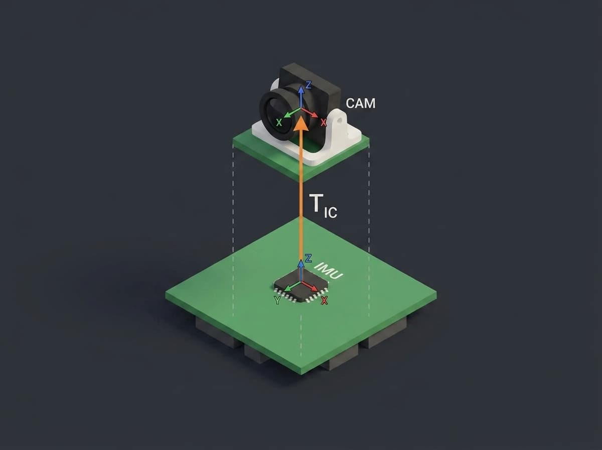
The extrinsic transform T_IC links the IMU body frame to the camera optical frame.
Calibration Purpose
Camera-IMU extrinsic calibration estimates two artifacts per drone:
- Spatial transform
T_IC: a 4x4 rigid-body matrix containing the rotation (3 DoF) and translation (3 DoF) between the IMU body frame and the camera optical frame. - Temporal offset
t_d: a scalar in milliseconds representing the clock offset between the camera shutter timestamp and the IMU sample timestamp. Even with hardware sync, exposure delays, USB transmission jitter, and rolling shutter introduce 1-50 ms of skew.
Both parameters are per-unit, not per-design. Two drones with identical CAD files will have different T_IC because the IMU chip's MEMS structure has a few hundred microns of placement tolerance on the PCB, and the camera module varies by similar amounts in its mechanical mount. Production calibration captures this variance once at end-of-line. The runnable template validates translation and time offset; production rotation validation follows the same pattern with T_IC's rotational block.
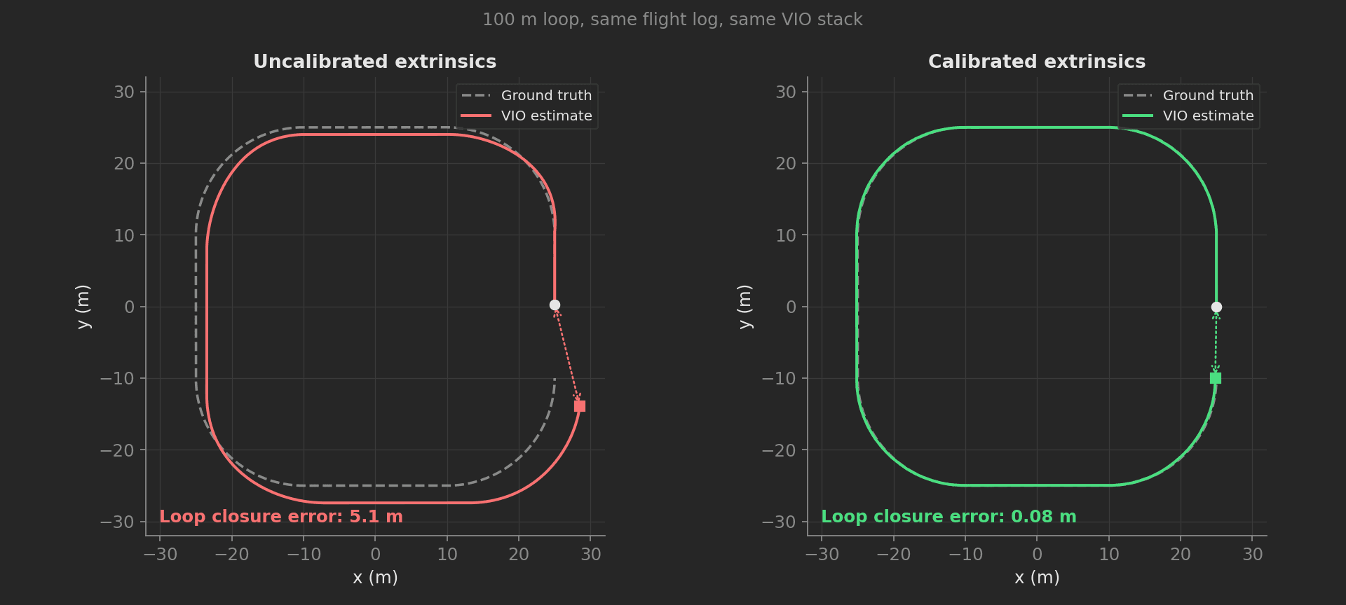
Same flight log and VIO stack, before and after camera-IMU calibration.
The production procedure is based on the Kalibr toolbox (ETH Zurich), the de facto industry standard. The drone is moved through an excitation pattern in front of a known calibration target while the camera records images and the IMU streams samples. A continuous-time batch optimizer estimates T_IC and t_d jointly with IMU biases and target poses. Per-unit factory calibration addresses a leading cause of autonomy-related field returns: visual-inertial divergence in aggressive maneuvers.
This template is also a working tour of the framework's execution model: a phase dependency graph whose independent checks run in parallel, an executable shell phase, a timeout on the optimizer, and a then override that lets a non-critical check fail without stopping the run.
Equipment & Setup
To implement camera-IMU extrinsic calibration on a production line, the following are required:
- A rigid AprilTag calibration target (April grid 6x6, tag family 36h11, printed on a flat aluminum-backed board).
- A 6-DoF motion stage (robotic arm or manual handheld procedure with operator UI guidance).
- The Device Under Test (DUT) with camera and IMU rigidly mounted in the production airframe.
- Firmware capable of synchronized raw streaming of camera frames + IMU samples with hardware-stamped timestamps.
- A TofuPilot Framework procedure to validate the capture, run the optimizer, and write the results back to the DUT.
- The TofuPilot Dashboard to store calibration results for traceability, monitor per-unit drift, and tie each calibration to a serial.
Hardware Components
AprilTag Calibration Target
We use a 6x6 AprilTag grid (tag family 36h11), with 88 mm tag size and 26.4 mm spacing (0.3 tag size), matching Kalibr's example aprilgrid target. The grid is A1 size (594 x 841 mm), printed at 600 DPI on matte vinyl, mounted on a 6 mm aluminum-composite backing to ensure planarity within 0.3 mm across the surface. Matte finish eliminates specular highlights that confuse tag detection.
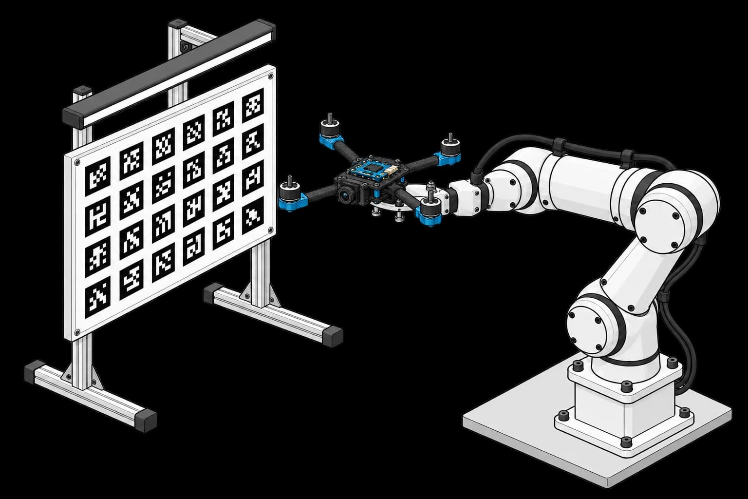
A rigid underside adapter holds the propeller-free quadcopter, camera and IMU for controlled motion in front of the target. The physical calibration target must match the procedure's grid specification.
The target must remain stationary and rigid during calibration. Print imperfections directly translate to calibration error; as a rule of thumb, a 0.5 mm bow in the board adds roughly 2 mm of translation error to T_IC. Replace targets every 6 months or whenever visible damage occurs.
Motion Stage
The drone must be moved with excitation in all 6 degrees of freedom during the capture. At minimum: yaw, pitch, roll rotations of ±30° plus translations of ±20 cm along each axis. Two approaches work:
- Robotic arm (e.g. a Universal Robots UR-series cobot such as the UR7e, with a custom non-magnetic end-effector). Deterministic, repeatable, fully scriptable. Capital cost ~$38k. Best for >50k units/year.
- Operator-guided handheld with on-screen pattern (figure-eight + axis tumble). Cost-free but adds operator variability. A tablet displays target coverage in real-time, similar to consumer smartphone gyro calibrations.
For most drone production lines we recommend starting with handheld + operator UI and graduating to a robotic arm when volume justifies it.
Lighting
Diffuse LED panel lighting at 800-1200 lux at the target surface, 5000-5500 K color temperature. Glare or shadows break AprilTag detection. The same lighting must be used across all units to avoid camera-exposure-induced timing drift. Avoid daylight near windows: overcast vs sunny days will shift exposure times and t_d estimates.
Custom Firmware
The DUT firmware must expose a synchronized streaming mode:
- Camera frames at 30 Hz, hardware-timestamped at the start of exposure (not end-of-frame). Resolution at production native (typically 1280x720 or 1920x1080). No autoexposure changes during capture.
- IMU samples at 200 Hz (or production VIO rate), hardware-timestamped at the gyro sample instant.
- Both streams share a single SoC clock. If the camera ISP and IMU sit on separate MCUs, the firmware must log the PTP or PPS sync offset at the start of the run.
A typical capture is 60 seconds of motion, yielding ~1800 frames and ~12000 IMU samples. The streams are written to SD or streamed over USB to the test station.
Test Procedure
Overview
The procedure is a small dependency graph. After a shell phase records the station platform, the capture downloads, then three independent checks fan out in parallel, and the optimizer runs once its two critical prerequisites pass:
- Record Station Platform: executable shell phase logging the station OS.
- Capture Recording: download the synchronized camera + IMU recording, check counts.
- Validate Excitation and Detect Tags: run concurrently, both depending only on the capture.
- Lens Health Check: non-critical vignetting check that cannot stop the run.
- Run Optimizer: estimates
t_dandT_ICunder a 120 s timeout, validates reprojection error, saves the result.
Why TofuPilot Framework?
TofuPilot Framework is a YAML + Python test framework built for hardware manufacturing. Instead of writing all your test logic, measurements, and limits inside Python code, you describe what the test does in a procedure.yaml file, and how in small Python phase files. The framework handles:
- Automatic Python environment management (via
uv) - Operator UI (no frontend code needed)
- Measurement validation and live charts
- Process isolation between phases and equipment plugs
Phases without dependencies between them run in parallel on a worker pool, so the excitation and tag checks overlap for free; the depends_on graph is the only scheduling code you write.
Project Structure
You can find the full source on GitHub. Run it locally with tofupilot run .; the mock plug synthesizes the capture with a known 12 ms clock offset that the estimator recovers.
The Procedure File
procedure.yaml declares the unit, the plug, and the phase graph. Note the executable phase (a shell command, no Python), the parallel fan-out after capture, the then override on the lens check, and the timeout on the optimizer:
procedure.yaml67 lines
name: Camera-IMU Extrinsic Calibrationversion: 0.1.0description: Captures a synchronized camera + IMU recording, validates motion excitation and tag visibility in parallel, then estimates the camera-IMU time offset and spatial transform.unit: auto_identify: true serial_number: default_value: "SN00001" part_number: default_value: "VIO-CAM-01"plugs: - name: Mock DUT description: Simulated DUT that returns a synchronized camera + IMU capture. python: plugs.mock_dut:MockDut key: dutmain: - name: Record Station Platform key: record_platform description: Records the station OS and architecture in the run log via a shell command. executable: command: "uname -a" - name: Capture Recording key: capture python: phases.capture measurements: - name: Frame Count key: frame_count validators: - operator: ">=" expected_value: 1500 - name: IMU Sample Count key: imu_sample_count validators: - operator: ">=" expected_value: 10000 - name: Validate Excitation key: validate_excitation python: phases.validate_excitation depends_on: - capture - name: Detect Tags key: detect_tags python: phases.detect_tags depends_on: - capture - name: Lens Health Check key: lens_health_check description: Non-critical vignetting check; a failure here does not stop the run. python: phases.lens_health_check depends_on: - capture then: fail: continue - name: Run Optimizer key: run_optimizer python: phases.run_optimizer timeout: 120s depends_on: - validate_excitation - detect_tagsA phase failing with then: fail: continue is still recorded as failed and fails the run outcome; the override only keeps the remaining phases executing so you collect the full diagnostic picture instead of stopping at the first non-critical red.
Motion Excitation Validation
A common production failure is operators (or robotic arms with sloppy programs) producing motion with insufficient excitation on one or more axes: typically yaw rotation is well-exercised but Z translation is not. We require the per-axis signal variance of both the gyro and the accelerometer to exceed a minimum before the expensive optimization runs. Insufficient motion produces an unobservable parameter that the optimizer will silently estimate as zero with high covariance.
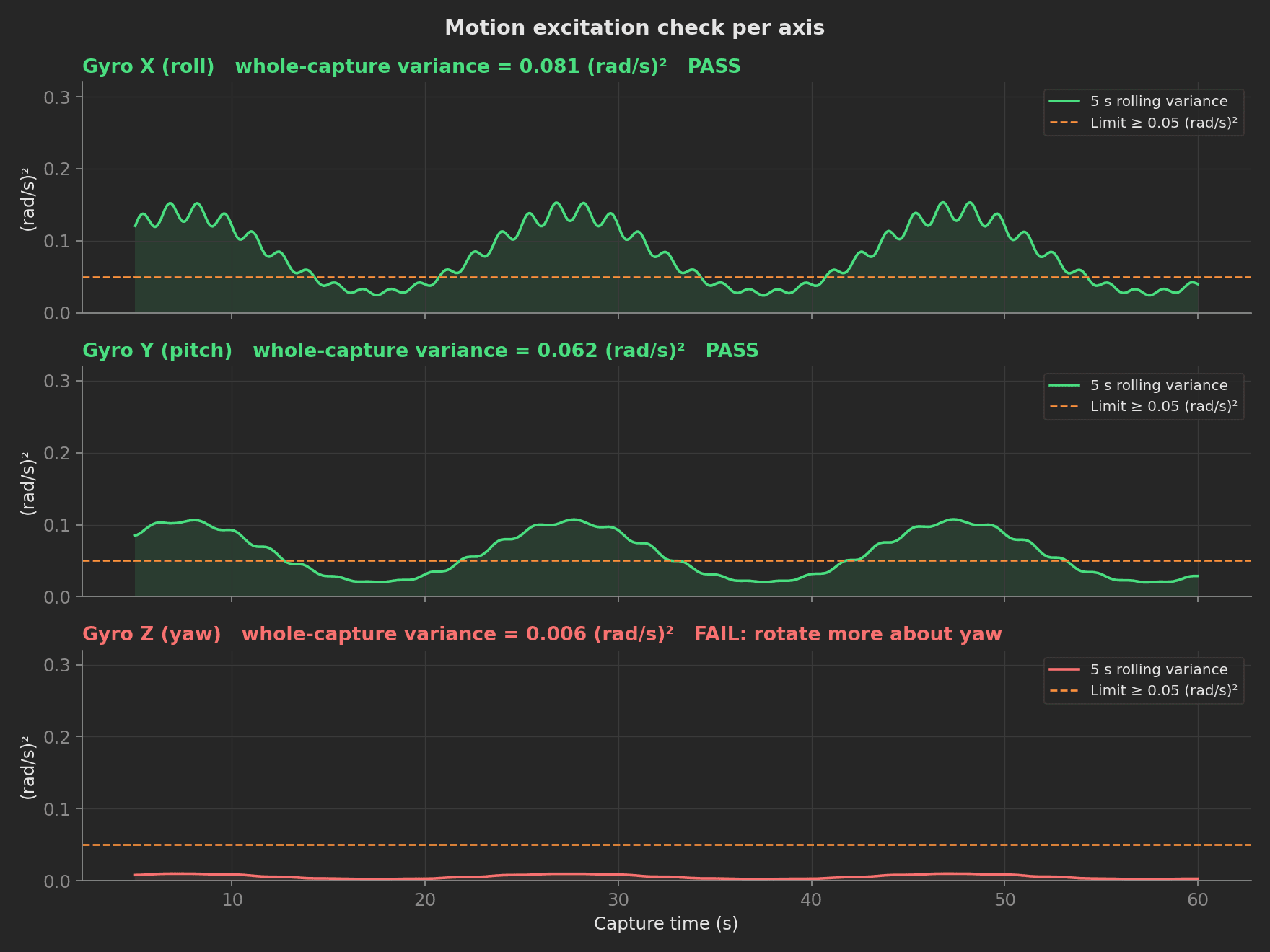
Per-axis excitation check: yaw was not exercised enough and the run fails before the optimizer starts.
import numpy as npdef validate_excitation(dut, measurements, log): """Check that the motion excited all six degrees of freedom. The optimizer silently produces unobservable parameters when an axis was not exercised, so each axis must carry enough signal variance before the expensive optimization runs. """ data = dut.get_capture() for axis in ("x", "y", "z"): gyro_var = float(np.var(np.asarray(data["gyro"][axis]))) accel_var = float(np.var(np.asarray(data["accel"][axis]))) setattr(measurements, f"gyro_excitation_{axis}", gyro_var) setattr(measurements, f"accel_excitation_{axis}", accel_var) log.info(f"Axis {axis}: gyro var {gyro_var:.3f}, accel var {accel_var:.3f}")Each of the six values is declared in the YAML with a >= 0.05 validator, one entry per axis:
measurements: - name: Gyro Excitation X key: gyro_excitation_x unit: (rad/s)² validators: - operator: ">=" expected_value: 0.05A poorly moved unit fails at this phase with a clear "rotate more" outcome instead of a cryptic optimizer divergence 90 seconds later.
AprilTag Detection
Each frame is processed by the tag detector. We require at least 12 of 36 tags visible in at least 80% of frames, and no more than 10% of frames rejected for motion blur (Laplacian variance below 100):
phases/detect_tags.py21 lines
import numpy as npMIN_TAGS_PER_FRAME = 12BLUR_VARIANCE_FLOOR = 100.0def detect_tags(dut, measurements, log): """Validate AprilTag visibility and motion blur across the capture.""" data = dut.get_capture() tags = np.asarray(data["tags_per_frame"]) blur = np.asarray(data["blur_variance"]) frames_valid = float(100.0 * np.mean(tags >= MIN_TAGS_PER_FRAME)) frames_blurred = float(100.0 * np.mean(blur < BLUR_VARIANCE_FLOOR)) measurements.frames_valid_pct = frames_valid measurements.frames_blurred_pct = frames_blurred log.info( f"{frames_valid:.1f}% frames with >= {MIN_TAGS_PER_FRAME} tags, " f"{frames_blurred:.1f}% blurred" )Because this phase and the excitation check both depend only on capture, the framework schedules them concurrently.
Time Offset Estimation
The template recovers the camera-IMU clock offset with a genuine cross-correlation search: interpolate the gyro stream onto shifted camera timestamps and keep the shift that minimizes the squared error. The mock capture embeds a true offset of 12 ms, and the estimator returns 12.0 ms:
utils/estimate_time_offset.py26 lines
import numpy as npdef estimate_time_offset(t_imu, gyro_z, t_cam, cam_rate_z, search_ms=50.0, step_ms=0.5): """Estimate the camera-IMU clock offset by cross-correlation. Scans candidate offsets, interpolates the gyro signal onto the shifted camera timestamps, and returns the offset (in ms) that minimizes the sum of squared differences. Positive means the camera clock lags the IMU clock. """ t_imu = np.asarray(t_imu) gyro_z = np.asarray(gyro_z) t_cam = np.asarray(t_cam) cam_rate_z = np.asarray(cam_rate_z) candidates = np.arange(-search_ms, search_ms + step_ms, step_ms) / 1000.0 best_offset, best_sse = 0.0, np.inf for offset in candidates: predicted = np.interp(t_cam - offset, t_imu, gyro_z) sse = float(np.sum((predicted - cam_rate_z) ** 2)) if sse < best_sse: best_offset, best_sse = float(offset), sse return best_offset * 1000.0Optimizer Phase
In production this phase wraps the full Kalibr batch optimizer (kalibr_calibrate_imu_camera; Kalibr is distributed as a ROS package, and the project provides Docker images that bundle the dependency). The template estimates the time offset for real; the spatial transform is drawn near the CAD nominal as a stand-in for the transform a real Kalibr run would estimate, and the reprojection series is synthesized from the capture's blur profile. The timeout: 120s on the phase covers everything it does, so a hung optimizer ends the phase with a timeout outcome instead of blocking the line. The per-frame reprojection errors are recorded as a multi-dimensional measurement with mean and max aggregations:
phases/run_optimizer.py51 lines
import numpy as npfrom utils.estimate_time_offset import estimate_time_offsetdef run_optimizer(dut, measurements, log): """Estimate the time offset and record stand-in extrinsics. The time offset is genuinely recovered by cross-correlating the gyro stream against the camera-observed angular rate. The translation is drawn near the CAD nominal as a stand-in for the transform a real Kalibr run would estimate, and the per-frame reprojection series is synthesized from the capture's blur profile. In production this phase wraps the full Kalibr batch optimizer and records its actual outputs. """ data = dut.get_capture() time_offset_ms = estimate_time_offset( data["t_imu"], data["gyro"]["z"], data["t_cam"], data["cam_rate_z"] ) measurements.time_offset_ms = time_offset_ms log.info(f"Estimated time offset: {time_offset_ms:.2f} ms") nominal = dut.read_nominal_extrinsics()["translation_mm"] rng = np.random.default_rng(11) translation = [float(v + rng.normal(0.0, 0.15)) for v in nominal] measurements.translation_x = translation[0] measurements.translation_y = translation[1] measurements.translation_z = translation[2] log.info( f"Translation: [{translation[0]:.2f}, {translation[1]:.2f}, " f"{translation[2]:.2f}] mm" ) # Per-frame reprojection error: healthy frames near 0.3 px, blurred # frames spike but stay under the 3 px ceiling. blur = np.asarray(data["blur_variance"]) errors = 0.28 + 0.04 * rng.standard_normal(blur.size) errors[blur < 100.0] += 0.9 errors = np.clip(errors, 0.05, None) chart = measurements.reprojection_error chart.x_axis = list(range(errors.size)) chart.y_axis.error = errors.tolist() chart.y_axis.error.aggregations.mean = float(errors.mean()) chart.y_axis.error.aggregations.max = float(errors.max()) log.info(f"Reprojection error: mean {errors.mean():.2f} px, max {errors.max():.2f} px") dut.save_calibration(translation, time_offset_ms) log.info("Extrinsics saved to DUT")Parameter Validation
We validate the optimized parameters against per-design bounds, derived from CAD nominals + manufacturing tolerance budget:
- Translation per axis: nominal ± 5 mm. The mock's CAD nominal X is 20.3 mm, hence the 15-25 mm window below. A value outside this typically indicates a misseated camera module or PCB rework defect.
- Time offset
t_d: |t_d| < 30 ms, which is also Kalibr's own--timeoffset-paddingdefault. Anything beyond indicates a missed hardware sync event or a USB driver buffering anomaly. - Reprojection error: mean < 0.5 px as a recommended production limit for a well-calibrated drone-grade camera; max < 3.0 px (outliers above are usually motion-blurred frames that slipped past blur detection).
procedure.yaml36 lines
measurements: - name: Translation X key: translation_x unit: mm validators: - operator: ">=" expected_value: 15.0 - operator: "<=" expected_value: 25.0 - name: Time Offset key: time_offset_ms unit: ms description: Camera-to-IMU clock offset estimated by cross-correlation. validators: - operator: ">=" expected_value: -30.0 - operator: "<=" expected_value: 30.0 - name: Reprojection Error key: reprojection_error title: Reprojection Error per Frame x_axis: legend: Frame y_axis: - legend: Error key: error unit: px aggregations: - type: mean validators: - operator: "<=" expected_value: 0.5 - type: max validators: - operator: "<=" expected_value: 3.0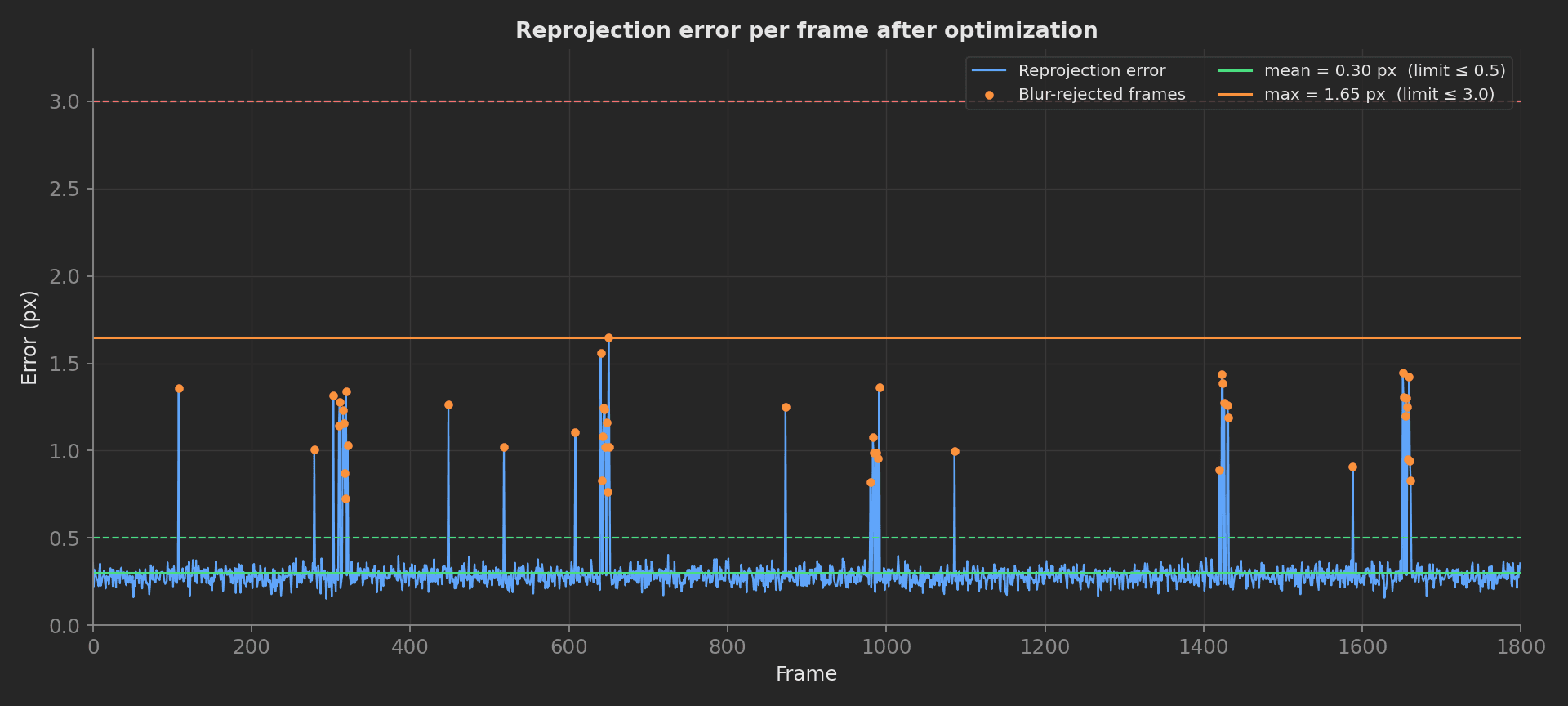
Reprojection error per frame with the mean and max aggregations validated against their limits.
These limits start from datasheet + CAD, and TofuPilot's control charts refine them to 3σ production limits after the first 500 units.
Saving Calibration to DUT
Validated T_IC and t_d are written to the autopilot's persistent storage. The format depends on the flight stack:
- PX4:
EKF2_EV_POS_X/Y/Zfor the camera position in the body frame, andEKF2_EV_DELAYfor the measured time offsett_d, via MAVLink parameter set. - ArduPilot:
VISO_POS_X/Y/Zfor the camera position;VISO_ORIENTcovers only coarse orientation presets. - Custom stack: a
.yamlwritten to/etc/vio/extrinsics.yamland a checksum logged to verify subsequent boot reads.
After write, the procedure reboots the DUT and reads back the parameters to confirm persistence. In this template the mock plug's save_calibration stands in for that write.