
Get the complete source, dependencies and setup instructions from the template repository.
Open the source on GitHubIntroduction
Boundary Scan Overview
IEEE 1149.1 boundary scan (JTAG) is the only practical way to electrically test a PCB whose components are BGA, fine-pitch QFN, or HDI without exposed test points. The standard defines a 4-wire Test Access Port (TCK, TMS, TDI, TDO; optional TRST) and a 16-state TAP controller. Every compliant pin on every JTAG-enabled IC has a boundary scan cell stitched into a shift register around the die periphery. Loading instructions like EXTEST, SAMPLE/PRELOAD, or BYPASS lets a tester drive and observe pin states without physical probe contact.
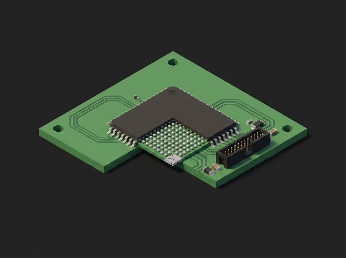
What no probe reaches: the ball grid under a BGA. A missing joint on one ball is an open on one net, and the scan cell behind that ball reports it through the header at the board edge.
Each JTAG-compliant device ships with a BSDL file (a VHDL subset) describing pin-to-cell mapping, instruction opcodes, and the IDCODE. The tester loads the BSDLs for every JTAG device on the board plus the netlist, generates the interconnect vectors, and runs them through the chain. Boundary scan is mandatory for any board with BGA balls, fine-pitch QFN pads, or HDI vias that a bed-of-nails or a flying probe cannot reach, which is most dense designs today.
Test Purpose
Boundary scan produces a per-board structural result plus in-system programming:
- Infrastructure: every IDCODE on the chain, the BYPASS length, the total cell count
- Interconnect test (EXTEST): walking patterns across every chain-reachable net, diagnosing shorts, opens and stuck-at faults to a net and a pin
- Cluster test: the DDR address and data lines exercised through the FPGA's cells
- In-system programming: the FPGA bitstream written through the same chain, with CRC readback
- PCOLA-SOQ coverage: the IPC score of what this test proves, per component and per net
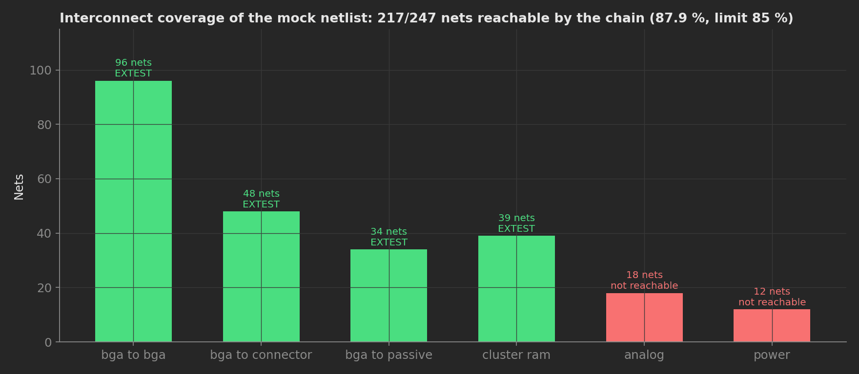
The mock netlist by class: everything with a scan cell on at least one end is reachable, the analog and power nets are not. The 85 % coverage limit is a property of the board design, not of the unit, so a drop below it means the wrong netlist or BSDL was loaded.
The procedure catches what ICT physically cannot: BGA cold solder, dry joint, missing via, MCU dead on arrival, bricked FPGA, wrong bitstream, bent connector pin, reversed BGA. Combined with ICT and AOI it gives near-complete structural coverage on modern dense PCBAs.
Beyond the test content, this template demonstrates four framework mechanics: a JSON measurement validated as a whole object for the IDCODE table, a list measurement validated against an empty list for the fault diagnosis, an attachment built in memory for the per-net report, and phase timeouts around the two long-running steps.
Equipment & Setup
To implement boundary scan testing on a production line, the following are required:
- A JTAG controller (TAP pod) with USB or Ethernet to the test station
- A boundary scan engine with vector generation, a BSDL library and flash drivers
- A current-limited DC supply for the bare board
- The Device Under Test (DUT): a populated, unprogrammed PCB with JTAG access (header or probe pads)
- CAD inputs: BSDL per JTAG device, the board netlist, the schematic for non-JTAG clusters
- A TofuPilot Framework procedure to drive the engine, record per-net results and validate every metric
- The TofuPilot Dashboard to log per-net fault diagnostics and trend BGA defect signatures
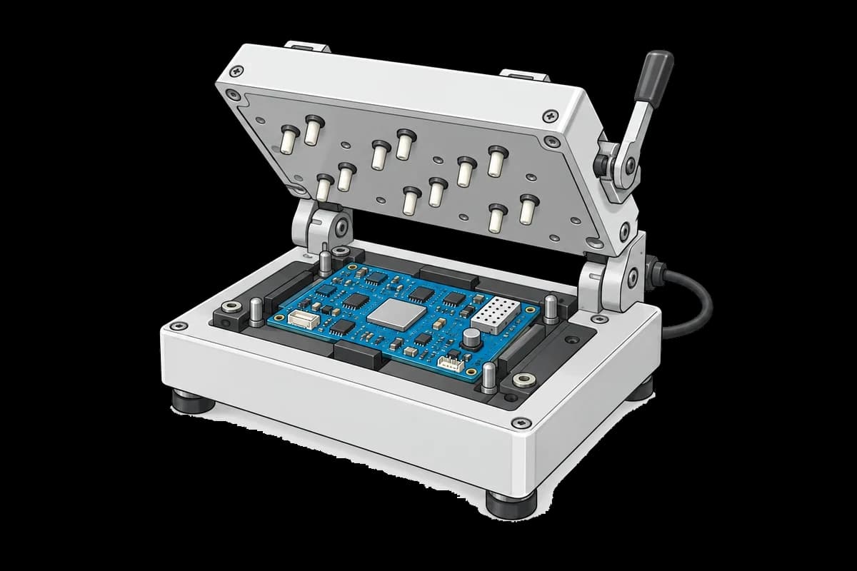
The board sits in a clamshell test fixture. The TAP controller, current-limited supply and test computer are not shown.
Hardware Components
JTAG Controller and Engine
Four production tool stacks dominate: ASSET InterTech ScanWorks, Goepel SYSTEM CASCON, XJTAG XJDeveloper / XJRunner, and JTAG Technologies ProVision with its JT37x7 controllers. All of them take BSDLs and a netlist, generate the interconnect vectors, diagnose failures to net and pin, and program flash and FPGAs through the chain. Vendor "fast flash" modes upload a small helper into the target's RAM and write flash through it instead of bit-banging every byte through the boundary cells, which is where the 50× speedups come from. For simple chains on in-house boards, OpenOCD or UrJTAG cover chain scan and programming without the vector generation.
CAD Inputs
- BSDL per IC: the pin-to-cell map, instruction register length and IDCODE of every JTAG device
- Board netlist (ODB++, IPC-2581, or a CAD export)
- Schematic for non-JTAG clusters (RAM, level shifters, glue logic)
- Cluster models describing transparent buffers and muxes
Missing BSDLs are the first blocker at NPI: allow lead time to obtain them from silicon vendors, or have the tool vendor generate them under support.
Custom Firmware
Boundary scan operates on bare boards with no firmware loaded; the vectors drive pins directly through the TAP. The ISP step of the same station programs the FPGA bitstream (and, on other designs, the bootloader and CPLD) as part of the same run, so structural test and first programming happen at one station.
Test Procedure
Overview
After the bare board is placed on the mat and the TAP cable plugged in, the procedure runs:
- Setup: current-limited 3.3 V on the board, quiescent current checked before any chain access.
- Infrastructure: scan the chain, compare every IDCODE with the BSDL expectations, check BYPASS length and cell count.
- In parallel: EXTEST interconnect test over the netlist with the per-net report attached, and the RAM cluster test.
- Program the FPGA bitstream through the chain and read the CRC back.
- Score PCOLA-SOQ coverage from the components and nets the test proved.
- Teardown: rail off before the TAP cable is unplugged.
Why TofuPilot Framework?
TofuPilot Framework is a YAML + Python test framework built for hardware manufacturing. Instead of writing all your test logic, measurements, and limits inside Python code, you describe what the test does in a procedure.yaml file, and how in small Python phase files. The framework handles:
- Automatic Python environment management (via
uv) - Operator UI (no frontend code needed)
- Measurement validation and live charts
- Process isolation between phases and equipment plugs
Project Structure
The controller plug is a mock of a three-device chain (an STM32H7 DAP, an Artix-7 FPGA, a CoolRunner-II CPLD) over a synthetic 247-net netlist, so the procedure runs green without a board. The bitstream is a real 256 KB file whose CRC32 the ISP phase expects. Run it with tofupilot run . --no-tui --no-kiosk --json. You can find the full source on GitHub.
The Procedure File
This is the exact file the template ships, verified end to end with the CLI:
procedure.yaml169 lines
name: Boundary Scan JTAG Testversion: 0.1.0description: Checks the TAP chain, runs the EXTEST interconnect test and the RAM cluster test over a bare PCBA, programs the FPGA bitstream through the same chain, and scores PCOLA-SOQ coverage.unit: auto_identify: true serial_number: description: "Scan the bare-board data-matrix" placeholder: "PCB-000000" pattern: "^PCB-\\d{6}$" default_value: "PCB-018234" part_number: default_value: "PCB-CTRL-V3"plugs: - name: DUT Supply description: Current-limited 3.3 V rail for the bare board (mock) python: plugs.psu:DutSupply key: psu - name: Boundary Scan Controller description: TAP pod plus vendor engine, three-device chain (mock) python: plugs.jtag:BoundaryScanController key: jtagsetup: - name: Power DUT key: power_dut python: phases.power_dut measurements: - name: Rail Voltage key: rail_voltage unit: V validators: - {operator: ">=", expected_value: 3.2} - {operator: "<=", expected_value: 3.4} - name: Quiescent Current key: quiescent_current unit: mA description: Unprogrammed board at 3.3 V. Above the limit means a short the chain would misdiagnose. validators: - {operator: "<=", expected_value: 80.0}main: - name: Infrastructure key: infrastructure python: phases.infrastructure measurements: - name: Chain Devices key: chain_devices validators: - {operator: "==", expected_value: 3} - name: IDCODEs key: idcodes description: IDCODE read from each device in TDI to TDO order, compared as one object against the BSDL expectations. validators: - operator: "==" expected_value: U1: "0x6BA00477" U4: "0x0362D093" U7: "0x06E58093" - name: BYPASS Length key: bypass_length unit: bits validators: - {operator: "==", expected_value: 3} - name: Scan Cells key: scan_cells validators: - {operator: "==", expected_value: 1406} - name: Interconnect key: interconnect python: phases.interconnect depends_on: [infrastructure] timeout: 300s measurements: - name: Nets Total key: nets_total - name: Nets Reachable key: nets_reachable - name: Net Coverage key: net_coverage unit: "%" validators: - {operator: ">=", expected_value: 85.0} - name: Vectors Applied key: vectors_applied - name: Faults key: faults description: Diagnosed faults as net, pin and fault model; empty on a good board. validators: - {operator: "==", expected_value: []} - name: Cluster Test key: cluster_test python: phases.cluster_test depends_on: [infrastructure] measurements: - name: Cluster Errors key: cluster_errors validators: - {operator: "==", expected_value: 0} - name: Cluster Lines key: cluster_lines validators: - {operator: "==", expected_value: 39} - name: Program Flash key: program_flash python: phases.program_flash depends_on: [interconnect, cluster_test] timeout: 600s ui: components: - key: isp_progress type: progress label: "FPGA bitstream" description: "256 KB through the fast-flash helper" default_value: 0 max: 100 measurements: - name: ISP Duration key: isp_seconds unit: s validators: - {operator: "<=", expected_value: 30.0} - name: ISP Throughput key: isp_throughput unit: KB/s validators: - {operator: ">=", expected_value: 100.0} - name: Flash CRC key: flash_crc validators: - {operator: "==", expected_value: "0xEFAA1C46"} - name: Flash CRC Match key: flash_crc_match validators: - {operator: "==", expected_value: true} - name: Coverage key: coverage python: phases.coverage depends_on: [interconnect, cluster_test] measurements: - name: PCOLA-SOQ key: pcola_soq unit: "%" description: IPC coverage score over components and nets for boundary scan alone; passives on the chain and unreachable nets cap it, ICT and AOI add the rest. validators: - {operator: ">=", expected_value: 50.0} - name: PCOLA-SOQ Breakdown key: pcola_breakdown - name: Net Coverage Check key: net_coverage_check unit: "%" validators: - {operator: ">=", expected_value: 85.0}teardown: - name: Power Off key: power_off python: phases.power_off measurements: - name: Rail Off key: rail_off unit: V validators: - {operator: "<=", expected_value: 0.1}Framework features to notice:
- JSON measurement compared as a whole:
idcodesis a dict of reference designator to IDCODE; the==validator compares the entire object, so a wrong variant, a missing device or a swapped chain order all fail the same measurement with the full table on the run. - List validated against
[]:faultscarries the engine's diagnosis (net, pin, fault model). A good board records an empty list; a failed board records exactly what failed, on the run, without a separate report. - Attachment from memory: the per-net CSV is built in the phase and attached with
attach.data, no temp file. - Timeouts on the long steps: 300 s for the interconnect run and 600 s for ISP bound a hung pod; the teardown still powers the board down.
- Fan-out and fan-in:
interconnectandcluster_testboth depend oninfrastructure;program_flashandcoveragedepend on both, so a broken chain skips everything downstream with one clear cause.
Infrastructure
Before any vector runs, the chain must be electrically sane: each device's IDCODE must match its BSDL, BYPASS must shift one bit per device, and the cell count must be the sum of the BSDLs. A broken TAP at one device blocks everything downstream, so this phase isolates a chain-level cause before any per-net result is reported:
def infrastructure(measurements, jtag, log): devices = jtag.scan_chain() idcodes = {d["ref"]: d["idcode"] for d in devices} log.info("Chain: " + ", ".join(f"{d['ref']} {d['part']} {d['idcode']}" for d in devices)) measurements.chain_devices = len(devices) measurements.idcodes = idcodes measurements.bypass_length = jtag.bypass_length() measurements.scan_cells = sum(d["cells"] for d in devices)Interconnect
The engine loads EXTEST on every device and applies walking patterns across every reachable net. The phase records the coverage, the vector count and the fault list, and attaches the per-net report as CSV:
phases/interconnect.py21 lines
import csvimport iodef interconnect(measurements, jtag, attach, log): results, faults = jtag.extest_interconnect(8) reachable = [r for r in results if r["reachable"]] coverage = 100.0 * len(reachable) / len(results) log.info(f"EXTEST: {len(reachable)}/{len(results)} nets reachable ({coverage:.1f} %), {len(faults)} faults") measurements.nets_total = len(results) measurements.nets_reachable = len(reachable) measurements.net_coverage = coverage measurements.vectors_applied = sum(r["vectors"] for r in results) measurements.faults = faults buf = io.StringIO() writer = csv.DictWriter(buf, fieldnames=["name", "class", "reachable", "vectors", "result"]) writer.writeheader() writer.writerows(results) attach.data(buf.getvalue().encode(), "interconnect_report.csv")Plug methods take positional arguments only (they cross a process boundary as JSON), which is why the vector count is passed as 8 and not vectors_per_net=8.
Program Flash
With the structure proven, the same chain programs the FPGA bitstream. The mock models a fast-flash helper at 180 KB/s; the CRC read back from the target is compared with the CRC of the file, and the progress bar tracks the transfer:
import zlibBITSTREAM = "firmware/fpga_bitstream_v1.3.bin"def program_flash(measurements, jtag, ui, log): expected = f"0x{zlib.crc32(open(BITSTREAM, 'rb').read()) & 0xFFFFFFFF:08X}" ui.isp_progress = 5 crc, seconds, rate = jtag.program_flash(BITSTREAM) ui.isp_progress = 100 readback = jtag.read_flash_crc() log.info(f"ISP {seconds:.1f} s at {rate:.0f} KB/s, CRC {readback} (image {expected})") measurements.isp_seconds = seconds measurements.isp_throughput = rate measurements.flash_crc = readback measurements.flash_crc_match = readback == expectedCoverage
The IPC PCOLA-SOQ framework scores what a test proves per component (Presence, Correctness, Orientation, Live, Alignment) and per net (Shorts, Opens, Quality), each 0, 0.5 or 1. Boundary scan scores well on presence, correctness, orientation and live for the chain devices and on shorts and opens for reachable nets; it cannot judge alignment or solder quality, and it says little about a passive hanging off a chain net. The phase computes the score from the component and net counts and reads the interconnect coverage through previous-results injection:
from utils.netlist import NET_CLASSESfrom utils.pcola import scoredef coverage(measurements, interconnect, log): components = {"jtag_device": 3, "cluster_ram": 2, "passive_on_chain": 34} reachable = sum(n for n, r in NET_CLASSES.values() if r) unreachable = sum(n for n, r in NET_CLASSES.values() if not r) pct, breakdown = score(components, {"reachable": reachable, "unreachable": unreachable}) log.info(f"PCOLA-SOQ {pct:.1f} % (components {breakdown['component_pct']} %, nets {breakdown['net_pct']} %)") measurements.pcola_soq = pct measurements.pcola_breakdown = breakdown measurements.net_coverage_check = float(interconnect.net_coverage)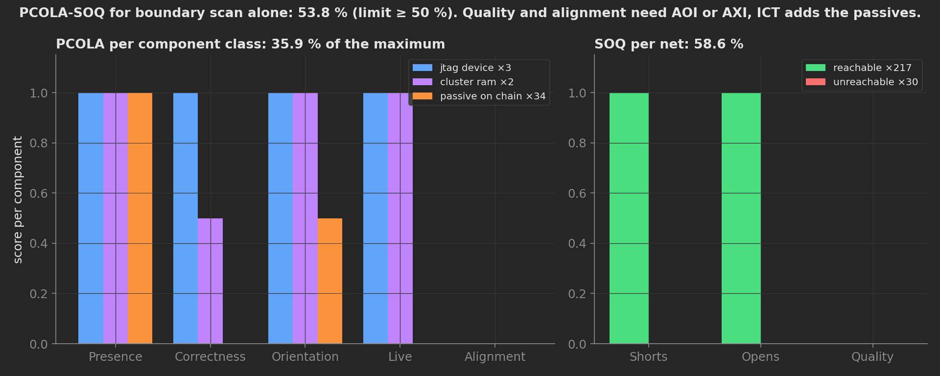
The honest number for boundary scan alone on this board: 53.8 %. The 34 passives on chain nets and the zero alignment and quality scores are what ICT, AOI and AXI add on top; the value of recording the score per run is that a board revision or a BSDL change moves it visibly.
Mock Plugs
The controller mock carries the three-device chain, walks the synthetic netlist, and computes the target CRC from the same bitstream file. Its method surface is what a wrapper around XJRunner, ProVision or ScanWorks has to provide:
plugs/jtag.py30 lines
CHAIN = [ {"ref": "U1", "part": "STM32H743 (ARM DAP)", "idcode": "0x6BA00477", "ir_length": 4, "cells": 0}, {"ref": "U4", "part": "XC7A35T Artix-7", "idcode": "0x0362D093", "ir_length": 6, "cells": 1214}, {"ref": "U7", "part": "XC2C64A CoolRunner-II", "idcode": "0x06E58093", "ir_length": 8, "cells": 192},]class BoundaryScanController: def __init__(self): self._nets = nets() print("TAP pod connected, TCK 10 MHz") def scan_chain(self): """Devices found on the chain in TDI -> TDO order, from their IDCODEs.""" return [dict(d) for d in CHAIN] def bypass_length(self): """Bits shifted through with every device in BYPASS: one per device.""" return len(CHAIN) def extest_interconnect(self, vectors_per_net=8): """Walking-1/0 interconnect test; returns per-net results and the fault list.""" results = [] faults = [] for net in self._nets: if not net["reachable"]: results.append({**net, "vectors": 0, "result": "not_covered"}) continue results.append({**net, "vectors": vectors_per_net, "result": "pass"}) return results, faultsThe ARM DAP on the MCU has no boundary cells (it is a debug port on the chain, not a boundary scan device), which is why its cell count is zero and why the interconnect vectors only drive the FPGA and CPLD pins. On a real bench, replace this class with the vendor engine's API; the phases, measurements, and limits stay exactly the same.