
Get the complete source, dependencies and setup instructions from the template repository.
Open the source on GitHubIntroduction
BMS Protection Overview
The protections on a battery management board are the reason the board exists. The analog front end (AFE) carries hardware comparators for cell over-voltage and under-voltage, for charge and discharge over-current on the sense resistor, for short-circuit discharge, and a temperature path through an external thermistor; each one has a programmable threshold and a programmable delay written into one-time-programmable memory at the end of the line, and each one, when it trips, opens the pack's charge or discharge FET. A board that leaves the factory with the wrong threshold, an unwritten configuration block, a swapped sense input, a mis-populated shunt or a thermistor from the wrong reel passes every voltage-accuracy test and fails the one time it matters.
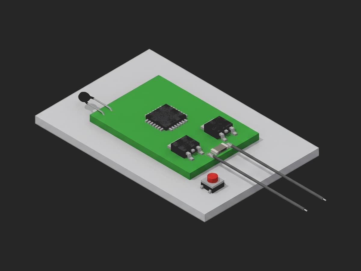
The parts under test on one board: the AFE with its comparators, the two power FETs it drives, the shunt whose voltage the over-current comparators read, and the thermistor whose resistance the over-temperature path converts to a temperature.
The datasheets are precise about what these comparators are allowed to do, and less precise than their front pages suggest. The TI BQ76952 guarantees its over-voltage threshold to ±2 mV at 25 °C over the full setting range, and to ±25 mV from -40 to 85 °C in the 3.036 to 5.06 V band where every real Li-ion OVP setting lives (see the BQ76952 datasheet); the thresholds themselves are set in 50.6 mV steps and the delays in 3.3 ms steps. Over-current accuracy is an absolute ±5 mV in the 56 to 100 mV band, which is ±8 % at a 60 mV setting; short-circuit detection is ±15 %; the short-circuit response at the fastest setting runs from 600 ns at 25 mV of overdrive to 8 µs at 3 mV, before the recommended 100 Ω / 0.1 µF input filter adds its own 10 µs time constant. The automotive BQ79616 is looser, not tighter, at ±24 mV on OV, and gets its safety rating from redundancy and a built-in comparator self-test rather than from precision. Every limit in this template is derived from these rows.
Test Purpose
The procedure records one protection fingerprint per board:
- Configuration read bit-exact before any stimulus, as one object, plus its CRC
- OV and UV trip point on every channel by binary search on a cell simulator, and the ALERT delay on each
- OCD1 and SCD thresholds by voltage injection across the sense-resistor inputs, the SCD response time at a stated overdrive, the DSG gate after the short, and the reset flags that tell a trip from a crash
- Temperature reported at two NTC resistances, the OTD trip by a resistance sweep, and an open thermistor that must raise a fault
- The configuration read again at teardown, so a threshold the test touched can never ship lowered
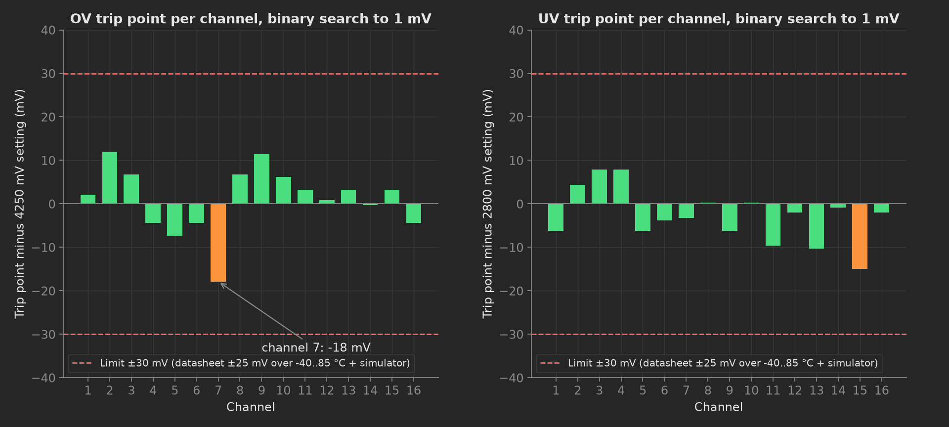
The mock board's sixteen OV and sixteen UV comparators against their settings: every trip inside the ±30 mV window derived from the datasheet's -40 to 85 °C row plus the simulator, channel 7's OV comparator 18 mV low and the one to watch across a batch.
The framework mechanics on show are JSON == on a whole configuration object before and after the test, multi-dimensional measurements with two curves and aggregations on both, limits copied from the AFE datasheet with delay limits expressed in quanta, a measurement that distinguishes a protection trip from a device reset, a two-point check that catches a wrong thermistor reel, and a search helper shared between two phases.
Equipment & Setup
To run this verification on a production line, the following are required:
- A battery cell simulator with one isolated, four-quadrant channel per cell input and sub-millisecond settling
- A current-sensor simulation channel: a ±10 V analog output driven onto the filter side of the shunt's sense inputs
- A programmable resistor on the thermistor input, with open and short states
- A timer input on the AFE's ALERT pin for delay measurement, and a digitiser on the DSG gate for the short-circuit response
- The Device Under Test (DUT): a 16S BMS PCBA with its production firmware and configuration
- A TofuPilot Framework procedure to sequence the stimuli, search the trip points and validate the limits
- The TofuPilot Dashboard to keep the per-board evidence that ISO 26262-7 asks a production line to keep
Hardware Components
Cell Simulator and Injection Source
The Chroma 87001 drives the sixteen cell inputs with 1 ms rise and fall and ±1 mV setting accuracy, and its software explicitly supports the OVP/UVP trip and release sequence. For the over-current tests the shunt is not driven with hundreds of amps; the AFE's OCC, OCD and SCD thresholds are all defined on V(SRP) - V(SRN), a differential voltage at two pins, and the comparator cannot tell a source from a shunt. A current-sensor simulation channel (Bloomy lists one as a standard item: analog voltage, ±10 V, 16-bit, ±0.5 %; an NI analog output does the same) is driven onto the high-impedance filter side of the shunt, where the 100 Ω series resistors isolate it from the sub-milliohm shunt. On the Chroma 8700 BMS test system the same function is an integrated current-sensing-unit stimulus.
The fixture holds the protection board and provides cell-sense, temperature-simulation and probe connections. The stimulus sources and timing instruments are external.
Programmable Resistor
The thermistor is substituted with a resistance, not a voltage. On a ratiometric AFE the trip temperature is a ratio of the thermistor to the on-board pull-up, so driving the pin with a DAC would bypass the pull-up and miss a wrong pull-up value. The Pickering 40-297A-050 covers 3 Ω to 1.51 MΩ at 0.125 Ω resolution with programmable open and short states; Bloomy's temperature simulation module offers 24 channels from 10 Ω to 500 kΩ at 1 % accuracy. At 60 °C a 10 kΩ NTC reads about 2.5 to 3 kΩ and moves 90 Ω per kelvin, so a 1 Ω module resolves 0.01 K; a decade box has no place in volume production.
Where the Limits Come From
None of IEC 62619, IEC 62133, UL 2054, UL 1973, ISO 6469 or GB 38031 specifies a BMS PCBA protection test; they apply abuse to cells and packs and judge the BMS by outcome. ISO 26262-7 requires that a safety-related characteristic be controlled in production and the evidence kept, which is why this test exists and is recorded per serial, but it hands out no millivolt. The limits are the AFE datasheet rows widened by the tester:
| Test | Limit | Basis |
|---|---|---|
| OV and UV trip point | setting ±30 mV | ±25 mV over -40..85 °C plus ±1 mV simulator, rounded |
| OV and UV delay | setting + 2 steps (≤ 107 ms at 100 ms) | 3.3 ms delay quantum, timed on the ALERT edge |
| OCD1 threshold | setting ±5 mV (55 to 65 mV) | ±5 mV absolute accuracy in the 56 to 100 mV band |
| OCD1 delay | ≤ 47 ms at 40 ms | 3.3 ms quantum |
| SCD threshold | setting ±20 % (160 to 240 mV) | ±15 % datasheet plus fixture |
| SCD response | ≤ 40 µs at +25 mV overdrive | 15 µs setting plus the input filter; the overdrive is part of the limit |
| Temperature at 25 and 60 °C, OTD trip | ±3 °C | ±0.5 % comparator (about ±1 K) plus 1 % resistor plus NTC tolerance |
| Configuration | exact match | no tolerance applies |
Two numbers in that table are traps. The OV front-page figure of ±2 mV describes the same part at 25 °C over the whole setting range; a limit built on it fails good boards. And an SCD response time without its overdrive and its filter is not a measurement: the same setting responds thirteen times faster at 25 mV of overdrive than at 3 mV, and the filter adds more than the whole comparator spec.
Test Procedure
Overview
The procedure maps the verification onto the framework's three stages. The configuration readback lives in setup: so no trip point is hunted on a board running the wrong protection block. The restore lives in teardown: so the stimulus goes off and the configuration is re-read even when a main phase fails.
- Setup: protection block and CRC read bit-exact.
- Main: OV trip point and ALERT delay, sixteen channels, binary search.
- Main: UV trip point and delay, one channel lowered at a time.
- Main: OCD1 and SCD by injection, SCD response, DSG gate, reset flags.
- Main: temperature at two NTC points, OTD sweep, open thermistor.
- Teardown: stimulus off, faults cleared, CRC again.
Every metric validates against limits declared in procedure.yaml, and results stream to TofuPilot as the per-board evidence.
Why TofuPilot Framework?
TofuPilot Framework is a YAML + Python test framework built for hardware manufacturing. Instead of writing all your test logic, measurements, and limits inside Python code, you describe what the test does in a procedure.yaml file, and how in small Python phase files. The framework handles:
- Automatic Python environment management (via
uv) - Operator UI (no frontend code needed)
- Measurement validation and live charts
- Process isolation between phases and equipment plugs
Project Structure
You can find the full source on GitHub. The ProtectionBench plug is a mock of the simulator, the injection source, the programmable resistor and the DUT's UART together, synthesizing a healthy board with every comparator inside the datasheet window, one OV channel 18 mV low, the released configuration in OTP and a thermistor of the right B value, so the procedure runs end-to-end without a bench or a board connected.
tofupilot run .For CI or bench automation, the same run executes headless:
tofupilot run . --no-tui --no-kiosk --jsonThe Procedure File
procedure.yaml declares the unit, the bench plug with its cell count as constructor argument, and the three stages with every measurement and limit:
procedure.yaml209 lines
name: BMS Protection Trip Verificationversion: 0.1.0description: Protection trip verification of a 16S BMS PCBA. Config read bit-exact, OV and UV trip point and delay on every channel by binary search on a cell simulator, OCD and SCD by sense-resistor voltage injection with the reset flags checked, over-temperature by two-point NTC substitution and open-thermistor fault, config re-read at teardown.unit: auto_identify: true serial_number: description: "Scan the board data-matrix before it goes into the fixture" placeholder: "BMS16-00000" pattern: "^BMS16-\\d{5}$" default_value: "BMS16-01743" part_number: default_value: "PCB-BMS-16S-R3" batch_number: default_value: "LOT-2026-37"plugs: - name: Protection Bench description: "Cell simulator, SRP/SRN injection source, programmable NTC resistor and DUT UART (mock, one plug per bench)" python: plugs.protection_bench:ProtectionBench key: bench config: cell_count: 16setup: - name: Config Readback key: config_readback python: phases.config_readback measurements: - name: Protection Config key: protection_config description: Every protection register decoded to engineering units and compared as one object against the released configuration. validators: - operator: "==" expected_value: ov_mv: 4250 ov_delay_ms: 100 uv_mv: 2800 uv_delay_ms: 100 ocd1_mv: 60 ocd1_delay_ms: 40 scd_mv: 200 scd_delay_us: 15 otd_c: 60 - name: Config CRC key: config_crc validators: - {operator: "==", expected_value: "0x3A7F"}main: - name: OVP Trip key: ovp_trip python: phases.ovp_trip timeout: 3m measurements: - name: OV Trips key: ov_trips title: Over-voltage trip point and ALERT delay per channel x_axis: legend: Channel y_axis: - legend: Trip point key: trip unit: mV aggregations: - type: max_dev_mv unit: mV validators: - {operator: "<=", expected_value: 30.0} - type: min_dev_mv unit: mV validators: - {operator: ">=", expected_value: -30.0} - legend: Delay key: delay unit: ms aggregations: - type: max_ms unit: ms validators: - {operator: "<=", expected_value: 107.0} - name: UVP Trip key: uvp_trip python: phases.uvp_trip depends_on: [ovp_trip] timeout: 3m measurements: - name: UV Trips key: uv_trips title: Under-voltage trip point and ALERT delay per channel x_axis: legend: Channel y_axis: - legend: Trip point key: trip unit: mV aggregations: - type: max_dev_mv unit: mV validators: - {operator: "<=", expected_value: 30.0} - type: min_dev_mv unit: mV validators: - {operator: ">=", expected_value: -30.0} - legend: Delay key: delay unit: ms aggregations: - type: max_ms unit: ms validators: - {operator: "<=", expected_value: 107.0} - name: Overcurrent Injection key: overcurrent_injection python: phases.overcurrent_injection depends_on: [uvp_trip] measurements: - name: OCD1 Trip key: ocd1_trip_mv unit: mV description: Setting 60 mV; the AFE's OC accuracy is +-5 mV in the 56-100 mV band. validators: - {operator: ">=", expected_value: 55.0} - {operator: "<=", expected_value: 65.0} - name: OCD1 Delay key: ocd1_delay_ms unit: ms validators: - {operator: "<=", expected_value: 47.0} - name: SCD Trip key: scd_trip_mv unit: mV description: Setting 200 mV, +-20 % (+-15 % datasheet plus fixture). validators: - {operator: ">=", expected_value: 160.0} - {operator: "<=", expected_value: 240.0} - name: SCD Response key: scd_response_us unit: µs description: "Step to DSG gate off at +25 mV overdrive, 100 MS/s. The 15 us setting plus the input filter; without the stated overdrive the number means nothing." validators: - {operator: "<=", expected_value: 40.0} - name: DSG Gate After SCD key: dsg_gate_after_scd_v unit: V validators: - {operator: "<=", expected_value: 1.0} - name: Reset Flags After SCD key: reset_flags_after_scd description: "A device that rebooted on the SRP/SRN transient turns its FETs off too; only the POR and watchdog flags tell a trip from a crash." validators: - operator: "==" expected_value: por: false wdt: false - name: OTP Thermistor key: otp_thermistor python: phases.otp_thermistor depends_on: [overcurrent_injection] measurements: - name: Temperature At 25 C key: temp_at_25c unit: °C validators: - {operator: ">=", expected_value: 23.0} - {operator: "<=", expected_value: 27.0} - name: Temperature At 60 C key: temp_at_60c unit: °C description: "10 kOhm NTCs all read 25 C at 25 C; a B=3977 reel where B=3435 belongs reads 55 C here and trips OTD late." validators: - {operator: ">=", expected_value: 57.0} - {operator: "<=", expected_value: 63.0} - name: OTD Trip key: otd_trip_c unit: °C validators: - {operator: ">=", expected_value: 57.0} - {operator: "<=", expected_value: 63.0} - name: TS Open Flagged key: ts_open_flagged description: An open thermistor must raise a fault, not report a plausible temperature. validators: - {operator: "==", expected_value: true}teardown: - name: Restore key: restore python: phases.restore measurements: - name: Faults After Restore key: faults_after_restore validators: - operator: "==" expected_value: ov: [] uv: [] ocd1: false scd: false otd: false ts_open: false - name: Config CRC After key: config_crc_after validators: - {operator: "==", expected_value: "0x3A7F"}Framework features to notice:
- A whole object, compared once.
protection_configvalidates nine registers with one==; the report shows which key differed. The same operator validates the fault map after restore and the reset flags after the short. - Two curves, both limited.
ov_tripsrecords the trip point and the delay per channel; the trip hasmax_dev_mvandmin_dev_mvaggregations, the delay hasmax_ms, each with its own limit. - Limits in the datasheet's units. ±30 mV, +2 delay quanta, ±5 mV absolute, ±20 %: the YAML carries the number and the description carries the datasheet row it came from.
- Trip versus crash.
dsg_gate_after_scd_vsays the FET went off;reset_flags_after_scdsays the device did not reboot to get there. Both are needed. - Shared code across phases.
uvp_trip.pyimportsfind_tripfromovp_trip.py; phases are plain Python modules. teardown:always runs. The CRC re-read at the end catches a threshold the test lowered and never restored.
Config Readback
Milliseconds, no stimulus, and the highest yield of any step in the sequence. The setup phase parks the pack at 3.6 V per cell, reads the protection block decoded to engineering units, records it as one object next to its CRC, and stamps the CRC onto the unit metadata:
from utils.recipe import CELL_COUNT, IDLE_MVdef config_readback(measurements, bench, unit, log): """Setup: the protection block read bit-exact before any stimulus. A board that left programming with the OTP unwritten fails here in milliseconds, with no fixture time spent hunting trip points.""" bench.set_all_cells_mv(IDLE_MV) bench.dut_clear_faults() measurements.protection_config = bench.dut_read_config() measurements.config_crc = bench.dut_config_crc() unit.metadata["config_crc"] = bench.dut_config_crc() log.info(f"Board {unit.serial_number}: config CRC {bench.dut_config_crc()}, {CELL_COUNT} cells at {IDLE_MV} mV")OVP Trip
One channel is raised while the other fifteen sit at 3.6 V; a binary search from a 300 mV window to 1 mV takes seven steps, each followed by a wait longer than the configured delay and a read of the fault register. The ALERT pin on a timer input gives the delay; software polling cannot resolve the 3.3 ms quantum. The search helper is shared with the UV phase:
phases/ovp_trip.py42 lines
import numpy as npfrom utils.recipe import CELL_COUNT, CONFIG, IDLE_MV, OV_SEARCH, SEARCH_RESOLUTION_MVdef find_trip(bench, channel, lo, hi, rising): """Binary search on one channel: seven steps from a 300 mV window to 1 mV. The other fifteen channels stay at idle the whole time.""" while hi - lo > SEARCH_RESOLUTION_MV: mid = 0.5 * (lo + hi) bench.dut_clear_faults() bench.set_cell_mv(channel, mid) tripped = bench.ov_tripped(channel) if rising else bench.uv_tripped(channel) if tripped: hi = mid if rising else hi lo = lo if rising else mid else: lo = mid if rising else lo hi = hi if rising else mid return 0.5 * (lo + hi)def ovp_trip(measurements, bench, log): """Over-voltage trip point and delay on every channel, one channel raised at a time while the rest sit at 3.6 V.""" trip = np.zeros(CELL_COUNT) delay = np.zeros(CELL_COUNT) for ch in range(1, CELL_COUNT + 1): trip[ch - 1] = find_trip(bench, ch, *OV_SEARCH, rising=True) delay[ch - 1] = bench.alert_delay_ms("ov") bench.set_cell_mv(ch, IDLE_MV) bench.dut_clear_faults() dev = trip - CONFIG["ov_mv"] measurements.ov_trips.x_axis = list(range(1, CELL_COUNT + 1)) measurements.ov_trips.y_axis.trip = trip.round(1).tolist() measurements.ov_trips.y_axis.trip.aggregations.max_dev_mv = float(dev.max()) measurements.ov_trips.y_axis.trip.aggregations.min_dev_mv = float(dev.min()) measurements.ov_trips.y_axis.delay = delay.tolist() measurements.ov_trips.y_axis.delay.aggregations.max_ms = float(delay.max()) worst = int(np.abs(dev).argmax()) + 1 log.info(f"OV trips {trip.min():.0f}..{trip.max():.0f} mV against {CONFIG['ov_mv']}, worst channel {worst} at {dev[worst - 1]:+.0f} mV, delay up to {delay.max():.1f} ms")Per channel is not optional: a swapped pair of sense inputs is invisible when only channel 1 is ramped. On a BQ76952 the OV threshold can also be trimmed in production with CAL_COV, applied between the top two cell pins, which corrects one comparator; the sixteen-channel search is still the test.
UVP Trip
The same search downward, with one rule the mock cannot teach but the article can: lower one channel. Dropping all sixteen together trips the stack's shutdown and the station reports a communication timeout instead of a UV result.
phases/uvp_trip.py26 lines
import numpy as npfrom phases.ovp_trip import find_tripfrom utils.recipe import CELL_COUNT, CONFIG, IDLE_MV, UV_SEARCHdef uvp_trip(measurements, bench, log): """Under-voltage trip point and delay, one channel lowered at a time. Lowering all sixteen together trips the stack shutdown and the station reports a comms timeout instead of a UV result.""" trip = np.zeros(CELL_COUNT) delay = np.zeros(CELL_COUNT) for ch in range(1, CELL_COUNT + 1): trip[ch - 1] = find_trip(bench, ch, *UV_SEARCH, rising=False) delay[ch - 1] = bench.alert_delay_ms("uv") bench.set_cell_mv(ch, IDLE_MV) bench.dut_clear_faults() dev = trip - CONFIG["uv_mv"] measurements.uv_trips.x_axis = list(range(1, CELL_COUNT + 1)) measurements.uv_trips.y_axis.trip = trip.round(1).tolist() measurements.uv_trips.y_axis.trip.aggregations.max_dev_mv = float(dev.max()) measurements.uv_trips.y_axis.trip.aggregations.min_dev_mv = float(dev.min()) measurements.uv_trips.y_axis.delay = delay.tolist() measurements.uv_trips.y_axis.delay.aggregations.max_ms = float(delay.max()) log.info(f"UV trips {trip.min():.0f}..{trip.max():.0f} mV against {CONFIG['uv_mv']}, delay up to {delay.max():.1f} ms")Overcurrent Injection
A voltage source on the filter side of the shunt sweeps V(SRP) - V(SRN) upward in 1 mV steps until OCD1 trips, then in 5 mV steps until SCD trips. The response time is then measured with a step to the trip point plus 25 mV, digitised on the DSG gate; the overdrive is stated with the result because the same comparator answers in 600 ns at 25 mV and 8 µs at 3 mV, and the input filter sits in front of both. After the short, the gate must be off and the reset flags must be clear: a device that browned out on the SRP/SRN transient reboots with its FETs off, which looks like a trip on the gate and is not one.
phases/overcurrent_injection.py43 lines
from utils.recipe import OCD_SWEEP_MV, SCD_OVERDRIVE_MV, SCD_SWEEP_MVdef overcurrent_injection(measurements, bench, log): """OCD1 and SCD thresholds by voltage injection across SRP-SRN: the comparators see a differential voltage and cannot tell a source from a shunt. Proves comparator, threshold config, fault path and FET drive; proves nothing about the shunt itself.""" bench.dut_clear_faults() ocd_trip = None for mv in range(*OCD_SWEEP_MV): bench.inject_mv(mv) if bench.ocd1_tripped(): ocd_trip = mv break ocd_delay = bench.alert_delay_ms("ocd1") bench.inject_mv(0) bench.dut_clear_faults() scd_trip = None for mv in range(*SCD_SWEEP_MV): bench.inject_mv(mv) if bench.scd_tripped(): scd_trip = mv break bench.inject_mv(0) bench.dut_clear_faults() # Response time with a stated overdrive; without the overdrive the # number is not comparable to anything. bench.inject_mv(scd_trip + SCD_OVERDRIVE_MV) scd_us = bench.scd_response_us(SCD_OVERDRIVE_MV) gate_v = bench.dsg_gate_v() resets = bench.dut_reset_flags() bench.inject_mv(0) bench.dut_clear_faults() measurements.ocd1_trip_mv = float(ocd_trip) measurements.ocd1_delay_ms = ocd_delay measurements.scd_trip_mv = float(scd_trip) measurements.scd_response_us = scd_us measurements.dsg_gate_after_scd_v = gate_v measurements.reset_flags_after_scd = resets log.info(f"OCD1 at {ocd_trip} mV in {ocd_delay:.1f} ms, SCD at {scd_trip} mV, gate off in {scd_us:.1f} us at +{SCD_OVERDRIVE_MV} mV overdrive, resets {resets}")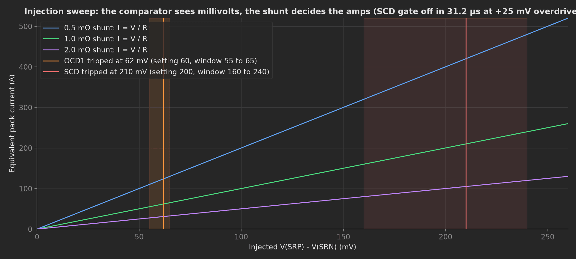
What injection proves and what it does not: the comparator trips at 62 and 210 mV, inside both windows. Which current that is depends entirely on the shunt, and the shunt is the one thing this phase never touches. A 1.0 mΩ resistor populated where 0.5 mΩ belongs trips at half the intended current (a nuisance, fails safe); 0.5 mΩ where 1.0 belongs trips at double (fails unsafe). Neither is visible here; a four-wire shunt measurement at ICT, or a real-current test at a temporarily lowered threshold, is the test for that.
OTP Thermistor
Two resistances, not one. Every 10 kΩ NTC is 10 kΩ at 25 °C, so a room-temperature point cannot tell a B=3435 reel from a B=3977 one; at 60 °C they differ by 21 % in resistance, and the wrong reel, read through the released B model, reports 6 K low and trips over-temperature late. The phase reads the DUT's temperature at both points, then sweeps the resistance down until OTD trips, then opens the thermistor and requires a fault:
phases/otp_thermistor.py40 lines
import mathfrom utils.recipe import CONFIG, NTC_BETA_K, NTC_POINTS_C, NTC_R25_OHM, NTC_SWEEP_OHMdef ntc_ohm(temp_c): return NTC_R25_OHM * math.exp(NTC_BETA_K * (1.0 / (temp_c + 273.15) - 1.0 / 298.15))def otp_thermistor(measurements, bench, log): """Over-temperature by resistance substitution on the TS pin, at two points: every 10 kOhm NTC reads 25 C at 25 C, only a hot point tells a B=3435 reel from a B=3977 one. Then a sweep down to the OTD trip, and an open thermistor that must raise a fault, not read a temperature.""" bench.dut_clear_faults() reported = {} for t in NTC_POINTS_C: bench.set_ts_ohm(ntc_ohm(t)) reported[t] = bench.dut_read_temperature_c() log.info(f"TS at {ntc_ohm(t):.0f} ohm ({t:.0f} C by the B={NTC_BETA_K:.0f} model): DUT reports {reported[t]:.1f} C") measurements.temp_at_25c = reported[25.0] measurements.temp_at_60c = reported[60.0] bench.dut_clear_faults() trip_c = None ohm = NTC_SWEEP_OHM[0] while ohm >= NTC_SWEEP_OHM[1]: bench.set_ts_ohm(ohm) if bench.otd_tripped(): trip_c = NTC_BETA_K / (NTC_BETA_K / 298.15 + math.log(ohm / NTC_R25_OHM)) - 273.15 break ohm -= NTC_SWEEP_OHM[2] measurements.otd_trip_c = float(trip_c) log.info(f"OTD trips at {ohm} ohm = {trip_c:.1f} C against {CONFIG['otd_c']} C") bench.dut_clear_faults() bench.open_ts() measurements.ts_open_flagged = bench.ts_open_flagged() bench.set_ts_ohm(NTC_R25_OHM) bench.dut_clear_faults()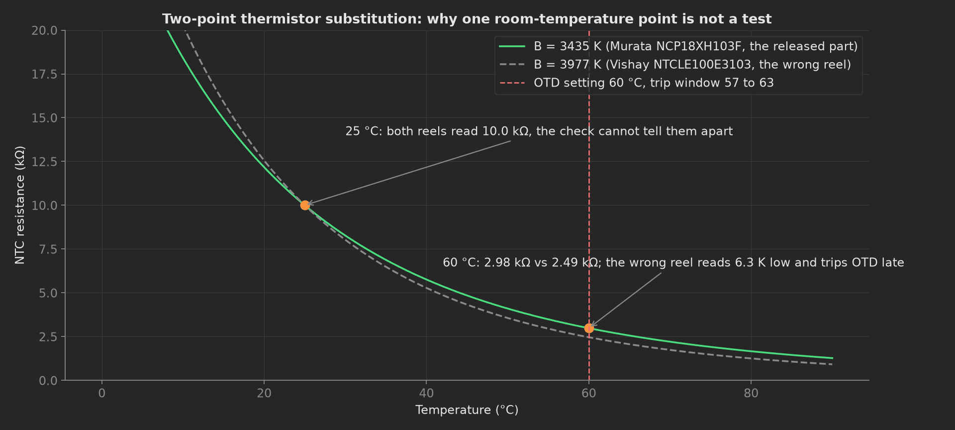
The two curves meet at the one point a single-point test would use. The Vishay NTCLE100E3103 is B=3977 K, the Murata NCP18XH103F is B=3434 K; both are "10k NTC" on a reel label.
Restore
The teardown phase switches the injection off, parks the cells, clears the faults and reads the configuration CRC again. Lines that lower a threshold over the service port to test over-current at a modest real current depend on this last read: a threshold left lowered ships a pack whose protection trips in normal use.
from utils.recipe import IDLE_MVdef restore(measurements, bench, log): """Teardown: stimulus off, cells at idle, faults cleared, and the config CRC read again so a threshold the test lowered can never ship lowered.""" bench.inject_mv(0) bench.set_all_cells_mv(IDLE_MV) bench.dut_clear_faults() measurements.faults_after_restore = bench.dut_read_faults() measurements.config_crc_after = bench.dut_config_crc() log.info(f"Restored: config CRC {bench.dut_config_crc()}, faults {bench.dut_read_faults()}")Mock Plug
ProtectionBench stands in for four instruments and the DUT because the DUT's fault registers depend on what the bench forces, and plugs run in separate processes. Its OV and UV comparators are drawn with a 7 mV standard deviation around the settings, channel 7's OV comparator is set 18 mV low, the OCD1 and SCD comparators sit 1.4 and 6 mV above their settings, the ALERT delay is the configured value plus a millisecond of latency, the SCD response is the 15 µs setting plus the input filter's response to the stated overdrive, and the thermistor model uses B=3435 K, the released part. Every method returns plain Python types because plug calls cross a JSON boundary; a measurement read back from measurements.<key> returns a proxy, so the phases keep locals for their log lines.
On a real bench, split the class into the cell simulator over SCPI, the injection channel on an analog output, the programmable resistor over its driver, and the DUT over pyserial with the ALERT pin on a counter input. Keep the overdrive in the SCD result, keep balancing off during every trip test (it modifies the OV and UV timing on the BQ76952), and add a four-wire shunt measurement at ICT for the one defect injection cannot see. The phases, measurements and limits stay the same.