
Get the complete source, dependencies and setup instructions from the template repository.
Open the source on GitHub ↗Introduction
Encoder and Commutation Calibration Overview
A frameless motor does not know where its rotor is. The drive commutates it from an encoder, and the number that ties the encoder's zero to the rotor's magnetic axis, the commutation offset, is set once, at the end of the line, per actuator. Get it wrong by 30 electrical degrees and the motor delivers 87 % of its torque and heats up; get it wrong by 90 and it delivers none. The encoder itself is a magnet ring glued to the rotor and read by a head a few hundred microns away, and its accuracy depends on how well the ring was centred: an eccentricity of 18 µm on a 30 mm ring is 120 arc-seconds of first-harmonic error, which the encoder's own self-calibration can remove and a mis-mounted ring cannot. And the joint's zero, the angle the robot's kinematics call zero, is a number found against a mechanical reference and written to the drive. Three calibrations, three writes to the actuator, each one verified before the next.
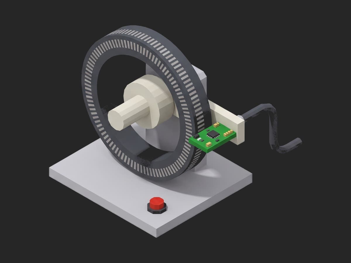
The rotor encoder: a magnetised ring on the shaft, read by a head on a bracket; the gap between the two and the centring of the ring are what the first phase checks.
The methods are the vendors'. Synapticon's drives run a commutation offset detection that finds the phase order, the electrical offset and the pole-pair count with the rotor free and unloaded (Synapticon documentation). Ben Katz's autocalibration for the MIT Cheetah actuators steps the d-axis forward and back and averages to cancel friction, low-passes over one electrical cycle to cancel cogging, and writes a 128-point lookup table (build-its). The RLS AksIM-2 datasheet gives ±0.05° before installation, typically ±0.025° after self-calibration, computes the ride height from the signal level to ±20 µm and flags a self-calibration run at over 300 rpm as invalid (AksIM-2 datasheet). Apptronik's actuation test engineer owns "motor and encoder calibration" among the production test methods with pass/fail criteria; Figure's manufacturing software test engineer writes "end of line software for programming, calibrating, and verifying subassemblies". This template is that software.
Test Purpose
The procedure writes three calibrations to one actuator and verifies each:
- Encoder health before anything is calibrated on it: signal level, ride height, error flag
- Phase order and pole pairs detected with the rotor free
- Commutation offset by the d-axis walk, run twice, agreement required; a lookup table written; the q-axis torque checked against expectation
- Encoder self-calibration run, then the accuracy verified against a reference table over one revolution
- Joint zero found against the hard stop, written and read back
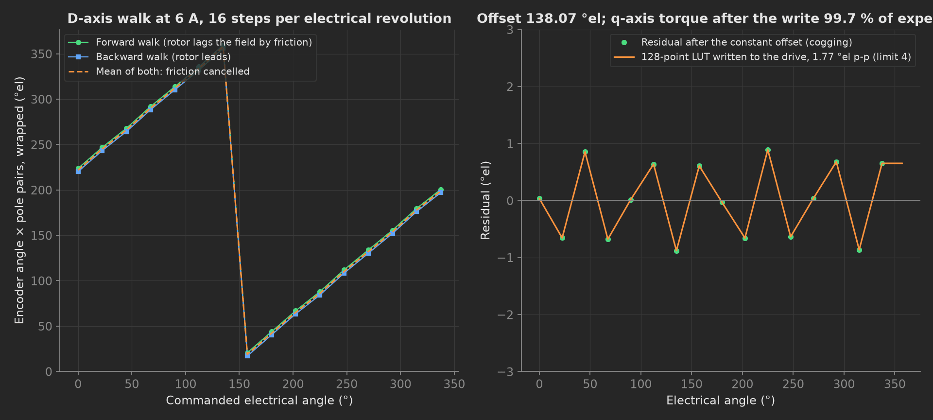
The mock actuator's d-axis walk: the rotor lags the field going forward and leads it coming back, by the same friction angle, so the mean of the two is the true relation; the constant part of that relation is the offset and the ripple is the cogging that the lookup table absorbs.
The framework mechanics on show are a calibration that writes to the DUT and then proves what it wrote, two independent runs required to agree as an aggregation with a limit, two curves in one measurement with the aggregations on one, string == validators on detection results, numbers recorded for the trend without a limit, and unit metadata the robot's bring-up reads later.
Equipment & Setup
To run this calibration on an actuator line, the following are required:
- The actuator's drive over EtherCAT, on a real-time target or a bench controller with current control
- Access to both encoders, the rotor's magnetic ring and the output absolute encoder, over BiSS-C or the drive
- A reference rotary table or a reference encoder on the output, for the accuracy verification
- A mechanical hard stop on the output, at a known angle from the joint zero on the drawing
- The Device Under Test (DUT): an assembled joint actuator with its production firmware, rotor free
- A TofuPilot Framework procedure to sequence the detections, compute the offsets, write them and verify them
- The TofuPilot Dashboard to trend the eccentricity before self-calibration, which is where a ring-gluing fixture drifting out of tolerance shows first
Hardware Components
Drive and Encoders
Elmo and Kollmorgen drives run on Figure's benches; Synapticon's Circulo integrates the drive with the encoder interfaces and exposes the offset detection as CoE objects (phase order at 0x2003:5, offset at 0x2001, pole pairs detected in the same run). The rotor encoder modelled is the RLS AksIM-2, an on-axis magnetic absolute encoder to 20 bits with a self-calibration routine that fits and stores the eccentricity harmonics and reports pass/fail on its status line; its ride height, the gap between ring and head, is computed from the signal level and is the number the setup phase gates on. The output encoder is a second absolute device on the reducer output, 19 bits here, and is the one the joint zero is written against.
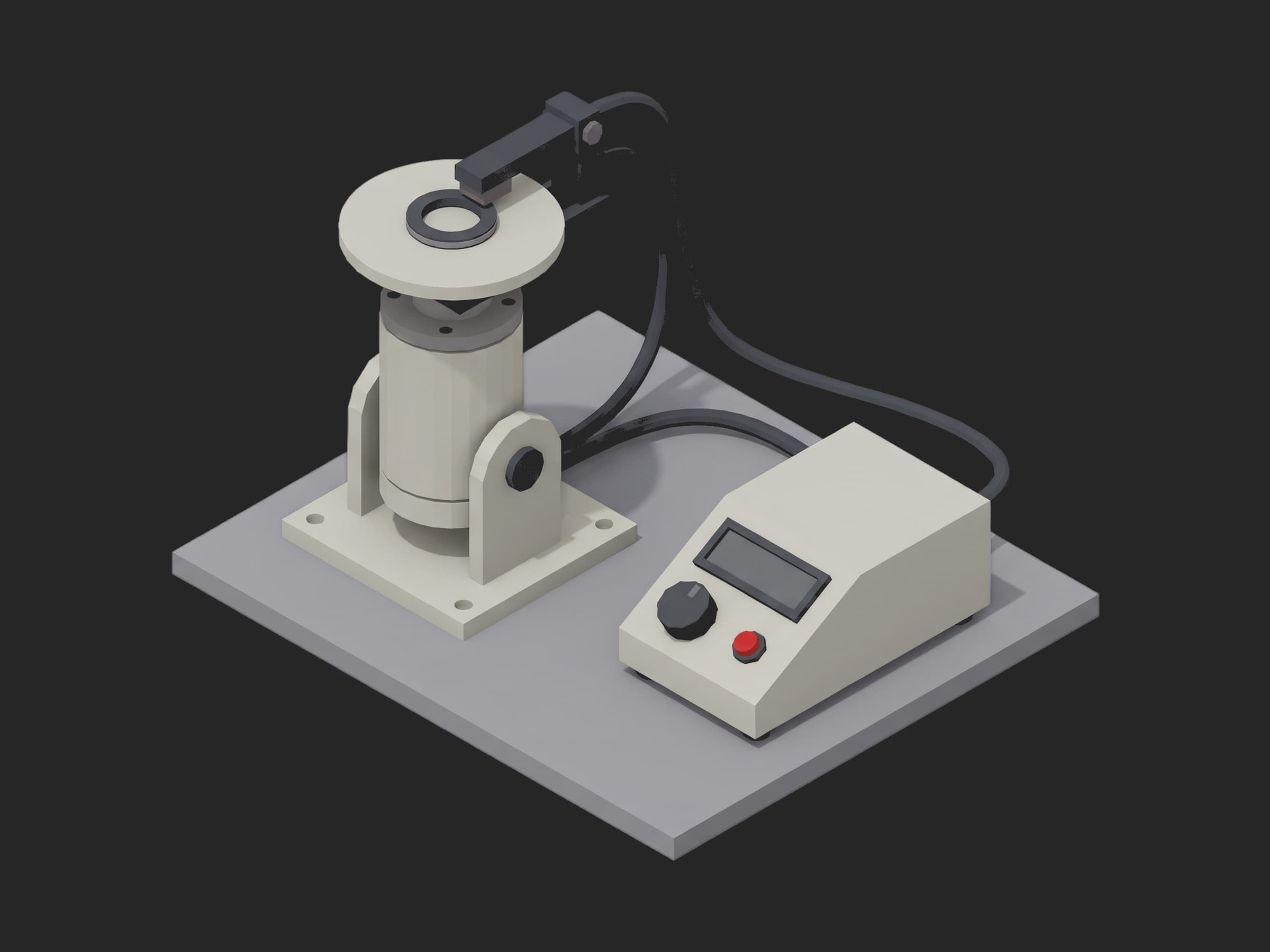
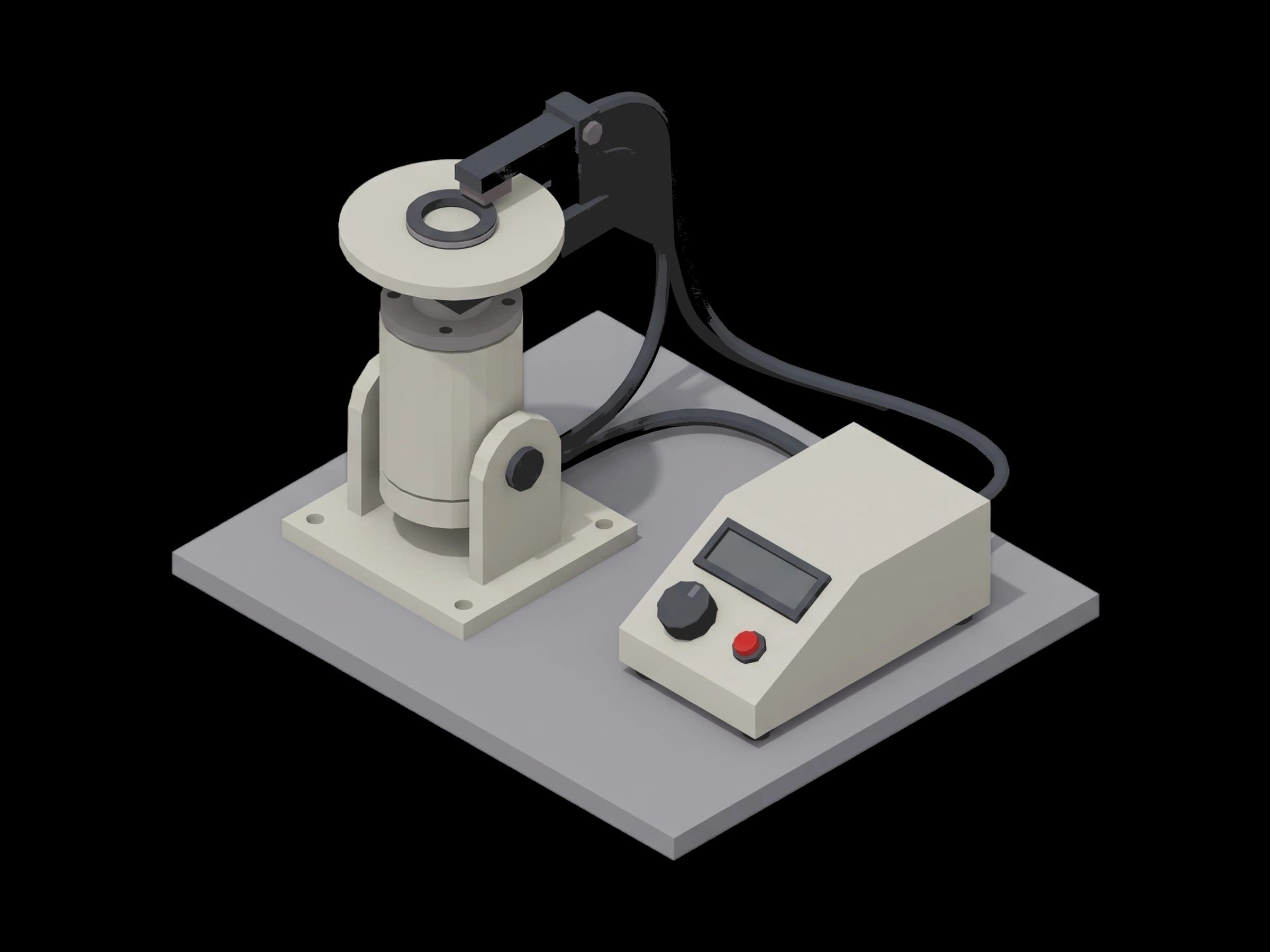
A single-axis station: the actuator upright in its bracket, the reference disc on the output flange read by a head on the arm, the drive and the reference interface in the instrument on the right.
Reference Table
The accuracy sweep needs a truth the module's encoder is compared to: an Ideal Aerosmith rate table carrying the actuator, or a Heidenhain RCN or Renishaw RESOLUTE reference ring on the output. The vendor's ±0.025° typical after self-calibration is 90 arc-seconds; a reference at 1 arc-second or better keeps the fixture out of the measurement.
Where the Limits Come From
No standard specifies an actuator calibration. The limits are the encoder and drive datasheets, plus the joint drawing:
| Test | Limit | Basis |
|---|---|---|
| Encoder signal level | ≥ 70 % | vendor status threshold |
| Ride height | 100 to 300 µm | vendor gap window for the ring size |
| Phase order, pole pairs | == UVW, == 21 | the motor's design |
| Offset repeatability | ≤ 1.5 °el between two runs | the walk's own noise floor plus margin |
| Lookup table peak-to-peak | ≤ 4 °el | cogging of a healthy stator; a magnet defect doubles it |
| Torque at offset | ≥ 99 % of expected | cos(8°) = 0.99: a residual offset error under 8 electrical degrees |
| Accuracy after self-cal | ≤ 120 arcsec max, first harmonic ≤ 20 arcsec | ±0.025° typical after self-cal, rounded up for the fixture; the first harmonic is the eccentricity the self-cal must have removed |
| Hard stop | 2.7 to 3.7° on the output encoder | 3.2° on the drawing, ±0.5° of assembly tolerance |
The eccentricity before self-calibration is recorded without a limit on purpose: it is the ring-gluing process, not the actuator, and a trend across a lot is how the fixture is caught drifting.
Test Procedure
Overview
The procedure maps the calibration onto the framework's three stages. The encoder health check lives in setup: so no calibration is stored on an encoder whose ring is mis-mounted. Disabling the drive lives in teardown: so the actuator is never left energised.
- Setup: encoder signal level, ride height, error flag.
- Main: phase order and pole pairs, rotor free.
- Main: d-axis walk twice, offset, lookup table, torque check after the write.
- Main: encoder self-calibration, accuracy sweep against the reference.
- Main: hard stop, joint zero offset written and read back.
- Teardown: drive disabled.
Every metric validates against limits declared in procedure.yaml, and results stream to TofuPilot as the actuator's calibration record.
Why TofuPilot Framework?
TofuPilot Framework is a YAML + Python test framework built for hardware manufacturing. Instead of writing all your test logic, measurements, and limits inside Python code, you describe what the test does in a procedure.yaml file, and how in small Python phase files. The framework handles:
- Automatic Python environment management (via
uv) - Operator UI (no frontend code needed)
- Measurement validation and live charts
- Process isolation between phases and equipment plugs
Project Structure
You can find the full source on GitHub. The CalBench plug is a mock of the drive, both encoders and the reference table together, synthesizing a healthy motor with a magnet ring 18 µm off-centre that self-calibration removes and a hard stop 3.2° from the joint zero, so the procedure runs end-to-end without a bench or an actuator connected.
tofupilot run .For CI or bench automation, the same run executes headless:
tofupilot run . --no-tui --no-kiosk --jsonThe Procedure File
procedure.yaml declares the unit, the bench plug, and the three stages with every measurement and limit:
procedure.yaml · 152 lines
name: Encoder and Commutation Calibrationversion: 0.1.0description: Encoder and commutation calibration of a humanoid joint actuator. Rotor encoder signal and ride height, phase order and pole-pair detection, electrical offset by a friction-cancelled d-axis walk run twice with a lookup table written, encoder self-calibration verified against a reference table, joint zero from the mechanical hard stop.unit: auto_identify: true serial_number: description: "Scan the actuator housing label" placeholder: "ACT-HIP-000000" pattern: "^ACT-[A-Z]{3}-\\d{6}$" default_value: "ACT-HIP-004813" part_number: default_value: "ACT-R100-60NM" batch_number: default_value: "WK-2026-37"plugs: - name: Cal Bench description: "Actuator drive over EtherCAT, rotor and output absolute encoders, reference rotary table on the output (mock, one plug per bench)" python: plugs.cal_bench:CalBench key: benchsetup: - name: Encoder Health key: encoder_health python: phases.encoder_health measurements: - name: Signal Level key: signal_pct unit: "%" validators: - {operator: ">=", expected_value: 70.0} - name: Ride Height key: ride_height_um unit: µm description: Magnet ring to readhead gap computed from the signal level; outside the window the ring is mis-mounted and the calibration will not hold over temperature. validators: - {operator: ">=", expected_value: 100.0} - {operator: "<=", expected_value: 300.0} - name: Encoder Error key: encoder_error validators: - {operator: "==", expected_value: false}main: - name: Phase Order key: phase_order python: phases.phase_order measurements: - name: Phase Order key: phase_order validators: - {operator: "==", expected_value: UVW} - name: Pole Pairs key: pole_pairs validators: - {operator: "==", expected_value: 21} - name: Commutation Offset key: commutation_offset python: phases.commutation_offset depends_on: [phase_order] timeout: 2m measurements: - name: D-Axis Walk key: walk title: Mechanical angle read at each commanded electrical angle, forward and back x_axis: legend: Electrical angle unit: ° y_axis: - legend: Forward key: forward unit: ° aggregations: - type: offset_edeg unit: ° - type: repeat_edeg unit: ° validators: - {operator: "<=", expected_value: 1.5} - type: lut_pp_edeg unit: ° validators: - {operator: "<=", expected_value: 4.0} - legend: Backward key: backward unit: ° - name: Torque At Offset key: torque_at_offset_pct unit: "%" description: q-axis step after the offset is written, measured over expected; cos of the residual angle error, so 99 % is 8 electrical degrees off. validators: - {operator: ">=", expected_value: 99.0} - name: Encoder Self Cal key: encoder_self_cal python: phases.encoder_self_cal depends_on: [commutation_offset] measurements: - name: Eccentricity Before key: eccentricity_before_arcsec unit: arcsec description: First-harmonic error the ring's mounting eccentricity produced before self-calibration; recorded, the mounting tolerance is what it trends. - name: Self-Cal Status key: self_cal_status validators: - {operator: "==", expected_value: ok} - name: Accuracy key: accuracy title: Module encoder minus reference table over one revolution, after self-calibration x_axis: legend: Angle unit: ° y_axis: - legend: Error key: error unit: arcsec aggregations: - type: max_abs_arcsec unit: arcsec validators: - {operator: "<=", expected_value: 120.0} - type: first_harmonic_arcsec unit: arcsec validators: - {operator: "<=", expected_value: 20.0} - name: Output Zero key: output_zero python: phases.output_zero depends_on: [encoder_self_cal] measurements: - name: Hard Stop key: hard_stop_deg unit: ° description: Output encoder reading at the stop; the stop sits 3.2 deg from joint zero on the drawing, so a reading far from it is a mis-assembled stop or a wrong encoder. validators: - {operator: ">=", expected_value: 2.7} - {operator: "<=", expected_value: 3.7} - name: Zero Offset key: zero_offset_deg unit: ° - name: Zero Offset Readback key: zero_offset_readback_ok validators: - {operator: "==", expected_value: true}teardown: - name: Release key: release python: phases.releaseFramework features to notice:
- Write, then prove. The commutation offset is written and then a q-axis torque step is measured against expectation; the zero offset is written and read back. Each calibration phase ends with a measurement that would fail if the write had not landed.
- Two runs, one aggregation. The d-axis walk runs twice;
repeat_edegis the disagreement between the two, with its own limit, so a noisy or slipping rotor fails on repeatability before it fails on torque. - Recorded without a limit.
offset_edeg,eccentricity_before_arcsecandzero_offset_degcarry no validators; they are the numbers the dashboard trends across actuators. - String
==on detection results.phase_order == UVWandself_cal_status == okvalidate the drive's and the encoder's own verdicts as strings. - Health before calibration. The ride height gate in
setup:refuses to calibrate a mis-mounted ring: a calibration stored on a ring outside its gap window holds on the bench and drifts in the robot.
Encoder Health
The setup phase reads the rotor encoder's status line and stamps the encoder resolution onto the unit metadata:
def encoder_health(measurements, bench, unit, log): """Setup: the rotor encoder's signal level and ride height before any calibration runs on it. A magnet ring mounted out of its gap window calibrates to a number and drifts with temperature.""" st = bench.encoder_status() measurements.signal_pct = st["signal_pct"] measurements.ride_height_um = st["ride_height_um"] measurements.encoder_error = st["error"] unit.metadata["encoder_bits"] = st["bits"] log.info(f"Actuator {unit.serial_number}: encoder signal {st['signal_pct']} %, ride height {st['ride_height_um']} um")Phase Order
The drive pulses the phases in sequence and watches which way the encoder moves; the pole-pair count falls out of the same run. Both are validated before the offset search, because a swapped phase or a wrong pole-pair configuration makes the search converge on a plausible wrong number:
from utils.recipe import POLE_PAIRSdef phase_order(measurements, bench, log): """Phase order and pole-pair count from the drive's detection routine, rotor free. Swapped phases or a wrong pole-pair configuration make the offset search converge on nonsense; both are checked before it runs.""" det = bench.detect_phase_order() measurements.phase_order = det["order"] measurements.pole_pairs = det["pole_pairs"] log.info(f"Phase order {det['order']}, {det['pole_pairs']} pole pairs (expected {POLE_PAIRS})")Commutation Offset
The rotor is locked to the d-axis at 6 A and the electrical angle is stepped through one electrical revolution in 16 steps, then back. Going forward the rotor lags the field by the friction angle; coming back it leads by the same amount; the mean of the two readings at each step is the friction-free relation. Its constant part is the offset, computed as a circular mean; its ripple is cogging, low-passed into a 128-point table. The whole thing runs twice and the two offsets must agree; then the offset and the table are written and a q-axis torque step is measured:
phases/commutation_offset.py · 39 lines
import numpy as npfrom utils.recipe import CAL_STEPS_PER_EREV, D_AXIS_CURRENT_A, LUT_POINTS, POLE_PAIRSdef commutation_offset(measurements, bench, log): """Electrical offset by the d-axis walk: lock the rotor to the field, step the electrical angle forward through one electrical revolution and back, read the encoder at every step. The forward and backward readings are averaged to cancel friction; the remaining ripple is cogging and is low-passed away over the electrical cycle. Run twice and require agreement, then write the offset and a lookup table.""" offsets = [] for run in range(2): walk = bench.d_axis_walk(D_AXIS_CURRENT_A, CAL_STEPS_PER_EREV) e = np.array(walk["e_fwd"]) m = 0.5 * (np.array(walk["m_fwd"]) + np.array(walk["m_bwd"])[::-1]) # Electrical angle the encoder implies at each step, minus the # commanded field angle, is the offset; wrap and average. implied = (m * POLE_PAIRS) % 360.0 diff = (e - implied + 180.0) % 360.0 - 180.0 offsets.append(float(np.degrees(np.arctan2(np.mean(np.sin(np.deg2rad(diff))), np.mean(np.cos(np.deg2rad(diff)))))) % 360.0) offset = float(np.mean(offsets)) repeat = float(abs((offsets[0] - offsets[1] + 180.0) % 360.0 - 180.0)) # Residual per electrical step after the constant offset: the LUT. resid = (diff - (offset if offset < 180 else offset - 360.0) + 180.0) % 360.0 - 180.0 lut = np.interp(np.linspace(0.0, 360.0, LUT_POINTS, endpoint=False), e, resid) bench.write_commutation(offset, lut.round(3).tolist()) torque_pct = bench.torque_step_response() measurements.walk.x_axis = walk["e_fwd"] measurements.walk.y_axis.forward = walk["m_fwd"] measurements.walk.y_axis.backward = walk["m_bwd"][::-1] measurements.walk.y_axis.forward.aggregations.offset_edeg = offset measurements.walk.y_axis.forward.aggregations.repeat_edeg = repeat measurements.walk.y_axis.forward.aggregations.lut_pp_edeg = float(lut.max() - lut.min()) measurements.torque_at_offset_pct = torque_pct log.info(f"Commutation offset {offset:.2f} edeg (runs {offsets[0]:.2f} / {offsets[1]:.2f}), LUT {lut.max() - lut.min():.2f} edeg p-p, q-axis torque {torque_pct:.1f} % of expected")Encoder Self Cal
The encoder's own routine runs (one turn at constant speed under 300 rpm, a harmonic fit of the eccentricity stored in the encoder), and its status is validated as a string. Then the reference table drives the output through one revolution and the module encoder is compared to it at every degree; the maximum error and the remaining first harmonic both carry limits, the second because it is exactly what the self-calibration must have removed:
phases/encoder_self_cal.py · 20 lines
import numpy as npfrom utils.recipe import ACCURACY_ARCSEC_MAXdef encoder_self_cal(measurements, bench, log): """Run the encoder's built-in self-calibration (one turn, harmonic fit of the ring eccentricity), then verify against the reference table over one revolution. The vendor's typical figure after self-cal is +-0.025 deg; the sweep is what proves it on this unit.""" cal = bench.self_calibrate() measurements.eccentricity_before_arcsec = cal["before_arcsec"] measurements.self_cal_status = cal["status"] sweep = bench.accuracy_sweep(360) err = np.array(sweep["error_arcsec"]) measurements.accuracy.x_axis = sweep["angle_deg"] measurements.accuracy.y_axis.error = sweep["error_arcsec"] measurements.accuracy.y_axis.error.aggregations.max_abs_arcsec = float(np.abs(err).max()) measurements.accuracy.y_axis.error.aggregations.first_harmonic_arcsec = float(2.0 * np.abs(np.fft.rfft(err))[1] / len(err)) log.info(f"Eccentricity {cal['before_arcsec']:.0f} arcsec before self-cal; after, max |error| {np.abs(err).max():.0f} arcsec against the reference (limit {ACCURACY_ARCSEC_MAX:.0f})")
The mock ring's 18 µm of eccentricity is 124 arc-seconds of first harmonic before self-calibration and gone after it; what remains is the second harmonic of the ring's ovality and the 21-per-revolution signature of the magnet poles, 31 arc-seconds at worst against a 120 limit.
Output Zero
The output is driven slowly into its mechanical hard stop until the torque threshold; the output encoder's reading there, minus the stop's angle from joint zero on the drawing, is the zero offset. It is written to the drive and read back, and the reading at the stop is itself limited, because a stop far from 3.2° is a mis-assembled stop or the wrong encoder:
from utils.recipe import HARD_STOP_TORQUE_NMdef output_zero(measurements, bench, unit, log): """Joint zero: drive the output into its mechanical hard stop until the torque threshold, read the output encoder there, write the offset so the stop reads its design angle, read it back.""" stop = bench.find_hard_stop(HARD_STOP_TORQUE_NM) design_stop_deg = 3.2 # the stop's angle from joint zero on the drawing offset = stop["stop_deg"] - design_stop_deg bench.write_zero_offset(offset) readback = bench.read_zero_offset() measurements.hard_stop_deg = stop["stop_deg"] measurements.zero_offset_deg = offset measurements.zero_offset_readback_ok = (readback == offset) unit.metadata["zero_offset_deg"] = round(offset, 4) log.info(f"Hard stop at {stop['stop_deg']:.4f} deg on the output encoder, zero offset {offset:+.4f} deg written and read back")At robot level the same idea scales: Unitree's G1 has a calibration mode with the robot suspended and every joint in a zero-torque state, and a contact-constrained joint-offset calibration in the literature halved the foot-height error from 4.3 to 2.2 mm RMS. The per-actuator zero here is the input to that.
Mock Plug
CalBench stands in for the drive, both encoders and the reference table. It synthesizes a true commutation offset of 137.4 °el, a friction lag of 1.8 °el each way and a cogging term of 0.9 °el at six times the electrical angle, a magnet ring with 18 µm of eccentricity on a 30 mm radius and a ride height of 210 µm, an accuracy after self-calibration of a second harmonic plus the 21-pole signature, and a hard stop at 3.2°. The torque step after the write returns cos of the residual offset error. Every method returns plain Python types because plug calls cross a JSON boundary; a measurement read back from measurements.<key> returns a proxy, so the phases keep locals for their log lines.
On a real bench, the class speaks the drive's CoE objects through pysoem (the d-axis walk is a sequence of current-mode commands with the electrical angle forced; Synapticon and Elmo both expose it), reads the AksIM-2's status and runs its self-calibration over BiSS-C, and drives the reference table over its own interface. Keep the rotor free and unloaded for the offset detection, under 300 rpm for the self-calibration, and write the offsets to non-volatile memory with a read-back. The phases, measurements and limits stay the same.