
A connector saver is a cheap, replaceable part placed between the unit under test (UUT) and the test fixture so that the saver, not the fixture, takes the wear of every plug and unplug. When its contacts wear out, the saver is swapped in minutes and the fixture wiring is never touched. Engineers also call it a sacrificial connector, a saver board, or a port saver for RF instrument ports.
Why Test Fixtures Need Connector Savers
Most connectors on a product are designed to be mated a handful of times: once at assembly, a few times in service. A production test station mates them hundreds of times per week.
| Connector family | Typical rated mating cycles | Cycles per day at 1 UUT every 5 min (8 h) |
|---|---|---|
| JST SH, GH, PH (wire-to-board) | 30 to 50 | 96 |
| Board-to-board mezzanine | 30 to 100 | 96 |
| MIL circular, D-Sub | 500 | 96 |
A fixture connector rated for 50 cycles is out of specification before the end of the first shift. Past that point the contact resistance rises and the contacts lose their retention force. The test station then produces intermittent failures that look like product defects: a motor line that drops for a few milliseconds, a telemetry frame lost, a current reading that drifts.
A connector saver moves that wear onto a part that is designed to be thrown away.
How a Connector Saver Works
The saver has two connectors:
| Side | Mated how often | Wear |
|---|---|---|
| UUT side | Every test run | High, the saver is replaced when it wears out |
| Fixture side | Only when the saver is replaced | Negligible |
The UUT cable plugs into the saver. The saver plugs into the fixture once, through a keyed connector. When the UUT-side connector reaches its cycle limit, the saver is unscrewed and replaced, and the fixture side sees one more mating cycle.
Common Forms
| Form | Typical use |
|---|---|
| Inline adapter (plug on one end, receptacle on the other) | MIL circular, D-Sub, Micro-D harness testers |
| Saver board (small PCB with two connectors) | Wire-to-board connectors on drones, ESCs, battery packs |
| Pogo pin block | Board-to-board connectors probed directly in a bed-of-nails fixture |
| Port saver | RF and microwave instrument ports (SMA, N, 4.3-10) |
Designing a Connector Saver Board
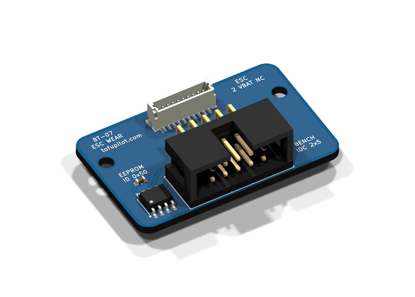
A saver board for a small wire-to-board connector is a two-layer PCB a few centimetres wide. The points below come from the saver in the picture, built for a drone ESC test bench:
| Part | Role |
|---|---|
| JST SH 10-pin socket | UUT side: takes the ESC cable on every run |
| IDC 2x5 right-angle box header | Fixture side: one ribbon carries the ESC lines and the I2C bus |
| M24C02 EEPROM (I2C 0x50) | Stores the saver's serial number and its mating-cycle count |
| Two M2.5 holes | Hold the saver on the bench, swapped with a screwdriver |
Pick One Fixture-Side Connector
The fixture side is mated rarely, so choose it for keying, cable availability and pin count, not size:
- One connector for everything the saver carries, so the saver is swapped with a single cable.
- A keyed connector (IDC box header, JST PH, Molex Micro-Fit) so the cable cannot go in reversed. Pick a latching version if the cable can be pulled.
- A family with standard cables on the market. A 10-way IDC ribbon is stocked everywhere and mates pin n to pin n.
- A right-angle header when the cable leaves along the board, so the plug does not stand up into the operator's hands.
Carry Only the Signals the Test Uses
Route only the lines the test reads or drives. Leave power pins that the bench does not use on isolated pads, and label them on the silkscreen. On the ESC saver, battery voltage stays on an unconnected pad, so pack voltage never reaches the bench through the saver. Check each new UUT lead with a multimeter before the first power-up: a lead wired in reverse still moves pack voltage onto a signal pin.
Keep the Pinout Readable
- Interleave ground with the signals on a ribbon: on the ESC saver, pin 1 and pin 7 are ground.
- Print the pinout on the silkscreen and mark pin 1. When the top side is full, the bottom side is free.
- Pour ground on both layers.
Make It Mechanically Replaceable
- Two screws (M2.5 or M3) through bare holes, with nuts held in the fixture.
- Leave finger room around any latch.
- Label every part on the silkscreen, including the EEPROM and its address.
Protect the Instrument Side
Series resistors and clamp diodes belong on the fixture side, not on the saver. The saver is replaced often; the protection should not be.
Give the Saver a Memory
A 2 kbit I2C EEPROM costs a few cents and turns the saver into a traceable part. The station reads it at the start of each run:
| Address | Content |
|---|---|
| 0x00 to 0x0F | Serial number, ASCII, padded with zeros |
| 0x10 to 0x13 | Mating-cycle count, unsigned 32-bit, little endian |
The count lives on the saver, not on the station, so it follows the saver when it moves to another bench. The EEPROM costs two signal lines on the fixture connector (SDA, SCL) plus 3.3 V and ground. Tie its write-control pin low so the station can update the counter, and keep the I2C pull-ups on the fixture side.
Read the Saver EEPROM in TofuPilot Framework
In the TofuPilot Framework, the EEPROM is a plug and the check is a phase at the start of the procedure. The plug below uses smbus2 on a Linux I2C bus, such as a Raspberry Pi station. On a bench where the I2C bus belongs to a microcontroller, the plug sends the same two transactions through it.
plugs/connector_saver.py38 lines
# M24C02 ID EEPROM on the connector saver: serial number and mating-cycle count.import structimport timefrom smbus2 import SMBus, i2c_msgclass ConnectorSaver: ADDRESS = 0x50 SERIAL, CYCLES = 0x00, 0x10 # 16-byte serial, then a uint32 counter def __init__(self, bus=1): self.bus = SMBus(bus) def __del__(self): self.bus.close() def read(self, offset, length): write = i2c_msg.write(self.ADDRESS, [offset]) read = i2c_msg.read(self.ADDRESS, length) self.bus.i2c_rdwr(write, read) return bytes(read) def write(self, offset, data): # M24C02 pages are 16 bytes: a write must stay inside one page self.bus.i2c_rdwr(i2c_msg.write(self.ADDRESS, [offset, *data])) time.sleep(0.005) # internal write cycle def serial(self): return self.read(self.SERIAL, 16).rstrip(b"\x00\xff").decode() def count_mating(self): (cycles,) = struct.unpack("<I", self.read(self.CYCLES, 4)) if cycles == 0xFFFFFFFF: # blank EEPROM cycles = 0 cycles += 1 self.write(self.CYCLES, struct.pack("<I", cycles)) return cyclesThe phase records the serial number and the count as measurements:
# Reads the saver identity and counts this run as one mating cycle.def check_connector_saver(measurements, connector_saver): measurements.saver_serial = connector_saver.serial() measurements.saver_mating_cycles = connector_saver.count_mating()The procedure declares the plug and puts the replacement limit on the count. At 80% of a 50-cycle rating, the run fails at cycle 41 and tells the operator to swap the saver before it starts producing false failures:
# Connector saver check, first phase of the procedureplugs: - name: Connector Saver key: connector_saver python: plugs.connector_saver:ConnectorSavermain: - name: Check Connector Saver python: phases.saver:check_connector_saver measurements: - name: Saver Serial key: saver_serial - name: Saver Mating Cycles key: saver_mating_cycles validators: - operator: "<=" expected_value: 40When to Replace a Connector Saver
Replace on a cycle count, not on a failure. A worn saver fails intermittently, and an intermittent failure costs more to diagnose than the saver costs to replace.
| Approach | How |
|---|---|
| Fixed cycle limit | Replace at 50 to 80% of the rated mating cycles of the UUT-side connector |
| Contact resistance check | Measure a known loop at each shift start; replace when it rises above a set limit |
| Failure-rate trigger | Replace when the station's first-pass yield drops while other stations hold steady |
Track Saver Wear with TofuPilot
With the EEPROM phase, every run uploaded to TofuPilot carries the serial number of the saver it ran through and the saver's cycle count at that moment.
- Follow the
Saver Mating Cyclesmeasurement across the procedure's runs: the count climbs with each run and drops back at each swap, so a saver nearing its limit is visible before the run fails. - Read
Saver Serialon a failed run to tie it to one saver. Failures that cluster at high counts point at the saver, not the product. - Compare the station's yield against the other stations running the same procedure. A drop on one station only, with failures spread across unrelated measurements, points at the fixture.
Without an EEPROM, the run count of a station since the last swap gives the same cycle count, as long as each swap date is noted. A saver that keeps failing early points at a mechanical problem: a cable pulled at an angle, or a misaligned fixture.